Leach's article in Audio mag of Feb 1976 is still online worth reading
Much more is here: Leach Amp Plans - Part 1
Last edited:
About Dr. Leach (I'm posting this here too, as it is closely related):
- The work of Dr. Leach, together with his philias and phobias, have been *gently* surpassed. To the point that reading Dr. Leach essays in 2010s can result misleading, if current "state-of-the-art" is not known.
- He had phobia to MOSFET. Excellent stuff is being done with MOSFET 40 years later. My personal mark is in class-D: >115dB SNR, 0.005% THD 5khz/8ohm/50W, and 0.05% THD 1khz/4ohm/1800W, from *same* circuit, with two TO-220 MOSFET as outputs, (SE vs. BR). No RF ringing. This makes the "lowtim" obsolete. The purpose of Prof. Leach in the "lowtim" was making an amplifier rugged and powerful enough for parties, yet accurate for low level listening.
- He had phobia to complex (2+ layer) PCB layouts. It was 1970s. Now we have the computers, the software, and PCB producers needed. Actually he was fearing layouts with many crossing nets requiring bridges (and speculative layout trial-and-error), he was not fearing complex circuits. This makes no sense. The absence of crossing nets is not representative of the quality of a circuit, it just simplifies layout work.
- His JFET limiter was actually the reflection of his weak understanding of some universal "features" of bipolar transistor physics. The LM13700 has far less part-to-part tolerance than JFETs, it does only need trimming for nulling. Noise and distortion is comparable to JFET. Gain control function is quadratic for JFET, linear for BJT VCA. Dr. Leach had phobia to ICs.
- He had other phobias too: current sources, etc. A "good" current source (intended for high voltage swings) requires (at least) *3* transistors, 2 of them thermally coupled (consult Widlar work). This was not so practical in 1970s. Now we have tiny SMD dual transistors costing less than the placement operation itself, plus 4+ layer PCBs with a copper plane just ~5 mils under the traces providing thermal coupling.
- Professor Leach had one good philia, though, but an expensive one. He documented all the design process for several pieces of common state-of-the-art (for 1970s) audio gear, and later published it online for DIYers. He created a DIYer community sharing designer knowledge. He helped students to build these designs as part of the courses. This is expensive because he had to obtain his earnings from a job as teacher. A professional designer can't publish things like that until the design is well established into the market.
There is a difference between "semiconductor linearization" and "local degeneration/compensation/feedback":
- Local compensation adjusts enough phase shift for stability, but does not necessarily provide linearization in return. If the reference for local feedback loop input summing is not fixed, like a fluctuating Vbe=log(Ic), local feedback is *not* linearizing. Negative feedback with non-linear action in summing node just amplifies summing node non-linearity.
- Semiconductor linearization aims at cancelling the non-linearity of one semiconductor with the non-linearity of another semiconductor (or element with varying properties). Mr. Leach did not expose that principle in any of their papers, so probably he was not sure, he hadn't experimented in that field (except for Vbe multipliers, which is a rather coarse approach).
Last edited:
I see it as an example of audio engineering practice. When Leach wrote that there was just a kind of vague idea that an ultra low thd at 1 khz ( measured with real resistor) does not yield any prediction about sonic impression. Impression of sonic quality and thd did not at all match. Thus the TIM story was an attempt of explanation of the mismatch. Then came psychoacoustics. The rule confirmed by several experiments the amplitudes of harmonics must decrease with "inverse logarithm" of the harmonics number. And so between some 50 milliWatts and -3 dB while the thd is not so much significant for sonic impression ( the latter is what can be sold in the market). Once hi end magazines made and pusblished such measurements many good amps turned out mediocre. Meanwhile research on human hearing demonstrated that old ideas about that sense were completely wrong. Indeed it takes some 100 msec to identify pitch but very fast transients can be heard as well so there are two "mechanisms".
To sum it up science is about predictability hence a theory must be enumerable hence computable. Experiments either refute or verify theory. Thus if thd theory is refuted by sonic impression it is not a verified theory but a working hypothesis. Trump's flat earth is a hypothesis that can be refuted by an experiment which contradicts.
Yes psychoaoustics is not a science as it is open. But nonetheless it is what we objectively have. As a reminder: acoustical instruments such as a cello .. the higher harmonics are about 30 to 40 dB above the fundamental yet no one had ever heard yelling the cello sounds distorted. I could post an extended list of , say, psychoacoustic experiments. There is just one conclusion: there is no physics of hearing.

"Rugged and powerful enough for parties, yet accurate for low level listening", and more importantly can be built by students on a studen's budget. Without a credit card. You and I can now afford to throw a $500 PCB run at any given project, but I suspect that was not always true. I clearly remember when I had to choose between peanut butter and a quart of ferric chloride (to go with the double sided FR4 blank panels I got for free and a Sharpie marker to do the layout). And semiconductors and transformer cores had to be scavenged.
indeed a valuable approach. As university student all my money went in text books...i had a tube amp i still remember four huge power tubes the plates glowing red and vaccuum..bluish. Psychedelic. Still the best subjective sonic quality of all my amps. Seductive magic." and more importantly can be built by students on a studen's budget..
All that local degeneration used in the original 100 watt version made it insensitive to just about everything. Put in any transistor within ratings and it worked. Even beyond ratings if you screened them (like using TIP41/2 as drivers if they pass about 140V, which most do). Insensitive to layout as long as there was some decoupling. No critical matching of input pairs if you could live with a little offset or were willing to trim it. You might not get the absolute best performance, but it was better than any receiver you could afford. And it would work converted to quasi comp to use surplus 2N3773's pulled out of old power supplies so they could take those $8 PNPs and shove em.
Wasn't so easy with the superamp. It really didn't like any stray inductance in any of the slave transistor wiring, or even too much capacitance from the master output's collector to ground. it typically needed fine adjustment of the output zobel with any given layout.
Wasn't so easy with the superamp. It really didn't like any stray inductance in any of the slave transistor wiring, or even too much capacitance from the master output's collector to ground. it typically needed fine adjustment of the output zobel with any given layout.
I did used a double output transistor pair version for about 10 years. At the end, I did tried a few amplifiers and also built some, but the Leach was really high standard. It is easy to listening, wants me to turn up the volume, while well detailed in both low, mid and high. I had commercial amps in that time for days and weeks from friends, including Audiolab 8000A, MIssion Cyrus. Also compared it to an Audio Innovations Alto in an AN system and that was clearly above, but non of the others. I've used it with high bias current. I had a really large heatsink on it, but still it got hot soon after switch on.
The living room life of my Leach ended when I built with help a 2A3 PSE amp, which is another league. Than, it reincarnated as a live event PA and served extremely well. Until it died a few month ago. One channel.
Negative side, I do remember I spent days with pairing transistors. I do not know if it is necessary or not, but I did.
If you measure parameters, yes, maybe it is outdated. If you listen to it, no, not at all.
JG
I built a low-TIM Leach amp from the article in Audio magazine making my own circuit board.
At first it sounded constrained so eventually I pulled the protection circuitry which resulted in great SQ!
It was by far the best sounding amp I ever heard up to that point through my Avid 105 speakers!
You probably guessed by now that I accidently shorted the outputs and then the amp sounded like crap. Ouch!
Last edited:
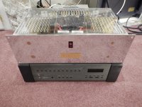
I have not built this amp as my skills are lacking but I do have several commercial examples, both The Leach Amp and The Leach Superamp mono versions. I find no fault with them. They are simply transparent. They do everything well. They make your music collection sound best overall. The Superamp was Stereophile's reference for a bit.
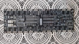
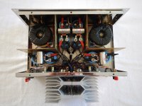
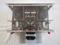
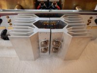
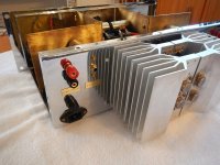
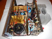
My Low Tim Leach amplifier. 100 watts x 2. Protection circuit by passed. I did not like the sound of the amp for many years and put it on the shelf.
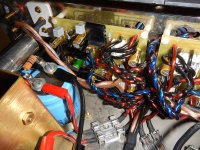
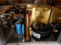
I had huge ground loop issues and thought it was my transformers, so I bought some expensive Piltron coil transformers. It didn't fix the problem. I discovered that I linked both my audio input grounds together, then ran one wire to a central spot. Not good. All must be run separately to a central ground spot. Super silent now.
As for sound. I noticed the treble and mids were fantastic, but the lows were weak. Compared to my Krell KSA 50. So back on the shelf it went.
Over the years, I have been modifying my custom house speakers, for about 20 years now. Experimenting with countless capacitors in the passive cross overs. I discovered a combination that defines audio bliss. Then I thought, I wonder if I can put these in my Leach amp...
Well, I then discovered by replacing, C6, 220uF on the board, to a non-polar Elna Silmic II capacitor, all the lows came in and the sound was even more irresistible. This is found in the feed back circuit. Then I thought... Maybe, just maybe, I will put put some of these special by-pass film capacitors in the feed back loop on each board. The film capacitors are physically large, so, I had to make room for them. They are small values. .01 uF. Then I turned it on... Oh my gosh, audio bliss! This Leach amp will out perform my Krell KSA 50 and my Krell KSA 250 in sound quality. I have not heard a better sounding amplifier than this. And I have heard many.
Unfortunately, my photos don't show the by-pass capacitors on the board. But you can just see the green Elna Silmic capacitor.
So, whoever has made a Leach amp. This is a must to do. It will leave your ears wanting more.
Attachments
-
 DSCN6843.JPG854.4 KB · Views: 721
 -
 DSCN6845.JPG874.6 KB · Views: 536
 -
 DSCN6849.JPG887.9 KB · Views: 512
 -
 DSCN6850.JPG848.4 KB · Views: 529
 -
 DSCN6851.JPG928.4 KB · Views: 536
 -
 DSCN6841.JPG893.3 KB · Views: 755
 -
 DSCN6834.JPG917.5 KB · Views: 761
 -
 DSCN6833.JPG916.8 KB · Views: 853
 -
 DSCN6854.JPG889.9 KB · Views: 855
Last edited:
So, originally I used two polar electrolytic capacitors. It had no bass. Then, when I used a bi-polar electrolytic capacitor, a Silmic, with a standard polypropylene by-pass film capacitor. It came alive and I had bass. The sound was really good. This shows how the capacitors play a huge roll in sound quality. In this case, the C6 is to cut off super low frequencies in the feed back circuit. Many amplifiers have these capacitors to eliminate low freqs and very high freqs. But, one huge issue... the capacitors change the sound immensely. Add some high end by-pass capacitors to everything, including your home speaker's passive cross-overs. The sound will drop your jaw!
Last edited:
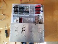
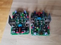
The leach superamp is what got me interested in hifi way back, so I decided to build my one one, after finishing my coffee, I will start mounting the output transistors, mine to has bipolar capacitor, the nice green ones, if all goes well I can power one channel up today.
Attachments
- Home
- Amplifiers
- Solid State
- Leach's Low TIM amplifier