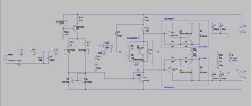
Hi, I'm currently building a simple amp for a 10 inch 150w subwoofer for a friend.
I don't have LTSpice models for mj11015/mj11016 , I just simulated with BD and some 2SC/2SA might not be the way to go, but...
- 100W output is what I aim here. 200W 30A output transistors I think are sufficent , Since you can get 60W from a pair of 2SC4468/2SA1695 100W/10A trans.
- Bruno.
I don't have LTSpice models for mj11015/mj11016 , I just simulated with BD and some 2SC/2SA might not be the way to go, but...
- Using darlingtons in the output stage might be harder to keep them not thermal run away? Should I place Q5 on the heatsink with the output trans or close to it?.
- is it ok to limit the bandwidth with C12 ? or I should not and build a op amp based low pass filter at the beginning.?
- 100W output is what I aim here. 200W 30A output transistors I think are sufficent , Since you can get 60W from a pair of 2SC4468/2SA1695 100W/10A trans.
- Bruno.
Attachments
Sakis, who ran a repair agency in Peraius for the beach bar trade, said darlington output bar amps blew up a lot more often than ones with separate driver transistors with their own heat sinks. Lots of cheapo consumer units put no heat sink on the driver. My dynaco ST120 was cheap but it came with them.
You want 150 w you need a pair of output transistors, even TO3. Four in all. To drive that much base you need something bigger than BD139/140 IMHO. I use MJE15028/29. If you don't have any highs you can get away with TIP41c/42c. Somebody now deceased said OT survivability was predicted by DC SOA. So 3 to 4 amps MJ15024/25, 1-2 amps MJ15015/16.1 amp 2sa1943/2sc5200. +-35 is a little lightweight for 150 w if you are driving 8 ohm speakers. Probably okay for 4 ohms. For survivability look at Peavey & Crown schematics. Those have a fan usually.
Yes, VAS Q5 should be on heatsink with the output transistors. The current adjustment should not fail open or short if the wiper loses contact. Paralleling the adjustment pot with a resistor or diode is good practice. Costs $.07 consumer products can't afford that.
The feedback line in from speaker to Q7 is a good way to inject radio interferance into Q7. Put 14 turns 20 ga wire around a china marker or AA battery (removed) near the output jack, parallel a 3 watt 10 ohm resistor. Dyna had 11 turns wire around the 2" diameter speaker caps, which worked. I had to install the 14 turns parallel resistor in an Allen organ amp to keep AM sports talk radio out of the Sunday service. Allen originally had a relay to disconnect the speakers at power up, which performed the RF block function until the contact became unreliaible at 30 years of age.
Calculating compensation to the feedback is over my head. I just follow plans like Apex. See AX14. Or naim schematics. Dyna got compensation wrong in 1966, the "TIP mod" about 1972 straightened that out.
Last edited:

In my schematic there are no pre drivers, just the Darlington output transistors MJ11015/MJ11016 .
Maybe use pre drivers and mount the vbe multip on them on a heatsink, separated form the output darlingtons?.
I thought i don't need pre drivers as MJ11015 has high gain .
Also heatsink will be actively cooled by a fan.
Maybe use pre drivers and mount the vbe multip on them on a heatsink, separated form the output darlingtons?.
I thought i don't need pre drivers as MJ11015 has high gain .
Also heatsink will be actively cooled by a fan.
Q11 BD139 should be big enough to drive the drivers Q1 Q2. Triple output gain (with predrivers) is for 3 or 6 pairs of output transistors. The output transistors are emitter followers, don't need a lot of gain. The drivers do.
I've used a single MJ15003 pair for 75 watts on +-35v, originally 40636 (2n3055 selected for more Vce). Crown D150 with single OT pair also was rated for that wattage. Peavey M-2600 for 75 w rating used 2 pair 2n5630-6130. MJ15015-16 has 60 v one pulse soa of 3 amps. 150 w into 4 ohms is 6.1 amps. You need more than one pair OT for 150 w. Even MJ15024/25 has only 5 amp one pulse soa rating.
If you don't have the MJ15015/16 yet, On is charging ~$10 for any to3 package. If you want to save bucks use MJL3281/1302, MJL4281/1402 mjw3281/1302 mjw21195/96 etc. Also easier to drill one hole, not 3 holes precisely lined up.
About the drivers, a sansui z3900 has 560 ohm resistors in emitter of the drivers. Apex AX6 has 220 ohms. You have 40 ohms.
The person that popularized the DCsoa rule for output transistor survival was AndrewT.
Last edited:
@indianajo I already have two pairs of MJ11015 / MJ11016 . So , can I connect them directly to Q11 ? or I must use pre drivers before them ?.
They say hFE 1000 (min ) at 20A .
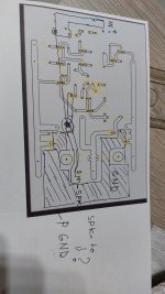
* For the Feedback is gonna be around 4cm on the PCB, should I leave it like that or use coax cable ? maybe with the shield on GND connected ?.
They say hFE 1000 (min ) at 20A .
* For the Feedback is gonna be around 4cm on the PCB, should I leave it like that or use coax cable ? maybe with the shield on GND connected ?.
Attachments

If the supply is actually +/-35V the trannies only need to see high current at 35V (any more volts And the current will be dropping rapidly even into a zero power load). The 11015 is good for 4A at 40V, which is plenty for 4 ohms (But not 2). It’s not the 15015, which is a POS. The 11015 has a decent amount of gain at 8A because it is a 30 amp device not 15. Even single C5200’s do fine down that low. The only issue is whether you can get the 28.3 volts peak off a real transformer supply. Bump it up to the 38 volt range (wont need more than 40) and you’re more likely not to come up maddeningly short at 90 or 95 watts. The 11015’s are fine up to +/-40 - but not much higher.
Predrvers may be a really good idea here. If you use them, the output stage can be run fully class B. You will still need output device bias, but with a triple EF it can be confined to the first stage of the darlington and still have “acceptable” crossover distortion. This is the way the old Phase Linears, early Crowns, and a lot of Peaveys (including the original CS800) were biased. Setting bias is a bit more complicated with integrated darlingtons but still possible. As bias voltage increases, you will start to get current in the 40 ohm base-emitter resistors. You will need some 10 mA, which will put about 400 mV on the “outputs”, which is where they go on those early benchmark amps. It will be fairly insensitive below 10-15 mA and the start to hockey stick. When that happens you have actual bias in the output pair. Properly compensated that is still thermally stable, but less so if the heat sink is too small (like the PLs). If you want 10 mA in the “outputs” you end up needing about 25mA in the devices to get there. Class B in the “outputs” with just 10 mA per device will sound like absolute garbage if this is done without the predrivers. Good enough for a subwoofer with them. If you are after minimum component count, set the device bias at 25 mA and call it good.
Predrvers may be a really good idea here. If you use them, the output stage can be run fully class B. You will still need output device bias, but with a triple EF it can be confined to the first stage of the darlington and still have “acceptable” crossover distortion. This is the way the old Phase Linears, early Crowns, and a lot of Peaveys (including the original CS800) were biased. Setting bias is a bit more complicated with integrated darlingtons but still possible. As bias voltage increases, you will start to get current in the 40 ohm base-emitter resistors. You will need some 10 mA, which will put about 400 mV on the “outputs”, which is where they go on those early benchmark amps. It will be fairly insensitive below 10-15 mA and the start to hockey stick. When that happens you have actual bias in the output pair. Properly compensated that is still thermally stable, but less so if the heat sink is too small (like the PLs). If you want 10 mA in the “outputs” you end up needing about 25mA in the devices to get there. Class B in the “outputs” with just 10 mA per device will sound like absolute garbage if this is done without the predrivers. Good enough for a subwoofer with them. If you are after minimum component count, set the device bias at 25 mA and call it good.
I you pull 20 A out of a MJ15015/16 in the linear range, they will roast for sure. 20 amp rating is for the fully saturated condition, Vce=2 or less, which is useless for audio amps. I think q11 can drive 2 pairs O.T. but I would use a heat sink on it. Even better, a TO220 vas instead of a BC139. I use a TO220 GE D44R4 for my vas on the AX6, 20 mhz ft, sounded great and ran 14 hours a day for 3 years. 70 w/ch Peavey M2600 has 2 output pairs, runs the drivers straight off the VAS.@indianajo I already have two pairs of MJ11015 / MJ11016 . So , can I connect them directly to Q11 ? or I must use pre drivers before them ?.
They say hFE 1000 (min ) at 20A .
* For the Feedback is gonna be around 4cm on the PCB, should I leave it like that or use coax cable ? maybe with the shield on GND connected ?.
Wgski's solution with a predriver works, but is a lot more complicated. I don't buy PCB's from ***** so every wire is a 5-10 minute proposition. AX6 is 72 wires.
If your board is inside a metal case with RF traps in and out, you should not pick up radio on your feedback transistor. Even with 4 cm land to it.
Cheapest way to get matched long tailed pair is buy an op amp. In sims longtailed pair are always matched, but not in real life. Q7 Q8 are long tailed pair. M-2600 used a TL072 but 5532 is quieter, also 33078 & NJM4580. More wires in the 2 zeners & 2 resistors & 2 capacitors for the +-15 v supply, but less wires for Q6, Q9 Q10 Q12 CCS. +-8 supply is fine if you are not inputting from a guitar amp speaker jack or a 7 vac earphone jack.
15015 would have a gain of about 2 at 20 amps. Even at 8 amps it won’t get better than 10. Some samples won’t get out of the single digits. Which puts a strain on drivers - prompting people to use TIP41’s for drivers. We all know how that sounds. If you used C1381/TIP41/MJ15015 triple it would sound ok, but then you’ve got to deal with mounting a TO-220 and a TO-3 for something that’s not as good as anything else you could come up with.
The 30 amp darlingtons actually work pretty well at this voltage - better than TIP35/6 + drivers. People often get the brilliant idea of using them at +/-50 - 60V, but that won’t end well. For that you need 2 pair of something.
The 30 amp darlingtons actually work pretty well at this voltage - better than TIP35/6 + drivers. People often get the brilliant idea of using them at +/-50 - 60V, but that won’t end well. For that you need 2 pair of something.
This is a sub amp. There will not be any highs. TIP41 as driver does not do highs well, I've tried it in the AX6. For $1 more each MJE15028/29 sound great at high freq. as drivers, but there aren't any highs in a sub amp. TO220 sheds the heat better than TO126 BD139/140. The BD139/140 we get in USA do NOT have the 190 Mhz Ft specification of the original Phillips parts. Ft of Fairchild/ON semi BC139/140 is WHONOZE?Which puts a strain on drivers - prompting people to use TIP41’s for drivers. We all know how that sounds. If you used C1381/TIP41/MJ15015 triple it would sound ok, but then you’ve got to deal with mounting a TO-220 and a
Fairchild and old ST fT as somewhere around 50 MHz on their versions of the BD139/40. It was specified as such on some of their other similar stuff - which was the higher power MJE170, 180 and 240 series. It’s all run on the same damn line. The “Big Deal” with the 139/40 was the lack of quasi-saturation - they maintain their gain down to a volt or two Vce. Big power devices start Losing It below 5 volts. When you are dealing with low voltage power supplies, it matters. For 200 watt amps it’s a don’t care because you’re never getting that close to the rail anyway.
Here, as drivers, predrivers or VAS, one of those with a small radiator fin is plenty. Output tranny average dissipation will top out around 30W each - 35^2/(pi^2*4) - with real-world full blast music about half that. As long as the output can muster a gain of 20 at 8 amps there is no issue at all. That’s asking the world of a 2N3055 (or it’s MJ15015 brother), but not for anything else one might use.
Slow drivers isnt so much about “lack of highs” as it is about increased crossover distortion. The more quickly the drivers can suck the base-emitter charge out of the outputs, the shorter and less intense the crossover glitch is before feedback. All those crossover waveforms you see in the textbook don’t do it justice in the real world - things get worse when you are charging and discharging capacitors at the same time. If the drivers start eating open loop HF response, the first thing that usually happens is the amp goes unstable, as the feedback tries to maintain response. If there is too large a capacitive load on the VAS the Miller pole splitting doesn’t work and you wind up with reduced phase margin. If it gets really high it can affect closed loop response too when you physically run out of feedback. Putting a high capacitance device in the VAS position is devastating. It will actually over stabilize it by adding its Cob to the Miller cap, lowering the frequency of the dominant pole. And dropping slew rate and a losing lot of the HF feedback. And the capacitor is nonlinear to boot, adding its own distortion.
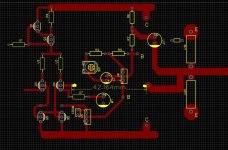
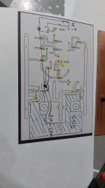
Mistake on FB should be on base not collector !.Good enough ?.
updated.
- Must I use separate ground for input, feedback to ground?. or the ground plane is ok. ?
Attachments
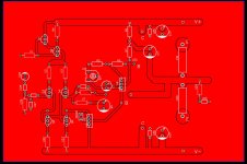
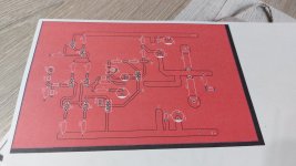
Ground plane is probably “good enough” given the application, but I probably would have tied the speaker, feedback, and input grounds to a single point, then ran a short trace from there to the ground plane.
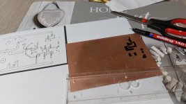
I see youre doing it the old fashioned way. And pre-drilling, which actuslly makes it easier to draw. It also makes doing double sided boards possible. Harder to do an actual ground plane though - it’s a lot of coloring to do.
If you are going to pre drill, you could do the heat sink or mounting bracket at the same time and not have to run flying wires.
I have been suggesting xxbrunoxx use two output pairs since post #4 to achieve his 150 w into 4 ohms. That would be 3.05 amps per transistor pair, or about the soa one pulse limit of MJ15015/16. No way a MJ15015 or even a MJ15024 be reliable at 8 amps.As long as the output can muster a gain of 20 at 8 amps there is no issue at all. That’s asking the world of a 2N3055 (or it’s MJ15015 brother), but not for anything else one might use.
He suggested 20 A would be doable, but that is reading too much into the Ic max spec, 15 A. Ic is for saturated operation. The 15015/16 soa rating at 60 v for one pulse is a much more restrictive 3.0 amps. Again, MJL3281//1302 etc is much cheaper, more soa than a 15015/16 and easier to machine the heatsink. Soa of MJ11015/16 appears to be 5 to 6 A at 35 v.
I don't know what kind of distortion the TIP41c./42c driving MJ15003 outputs were producing on the AX6 board, but the sine wave organ flutes in 8' and 4' ranks sounded fine. The top octave piano, tinkly bells, and cymbals sounded like ****. VAS was GE gold lead D44R4 with 20 mhz ft: no shortage of drive current to the drivers. (NOT the european D44) Changing the drivers to 30 mhz Ft MJE15028/29 made the AX6 sound as good as the opposite dynaco PC14 with 2n5320/22 drivers (50 mhz ft) and the djoffe closed loop idle bias current mod. SP2(2004) speakers have 2nd & 3rd HarmonicDistortion down 30 db from 5 w level 54 to 12 khz. xxBrunoxx does not need the highs for a sub amp.
Sorry, I don't analyze PCB layouts. I hook up in 3D with wire. One tip, do not make long parallel runs of sensitive inputs to bases parallel with high corrent outputs from collectors. Capacitive coupling can cause oscillation.
Last edited:
- Home
- Amplifiers
- Solid State
- Simple Sub amp