H
HAYK
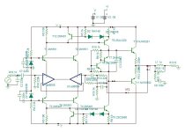
Most people use a leisure amp at low power averaging less than 5w but required to have 10 times headroom. This indicated a class AB amp. At low levels the crossover is the main trouble that results harsh high frequencies if the crossover is not right. Each pair follows a square law function, if a single EF is used as the case with CFP, the crossover can near perfection. With 2EF each pair should follow square law which results 4th order and 6th with 3EF which cannot get good crossover.
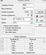
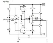
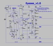
This Amp uses high current VAS that can pump 100ma in classA. To drive high gain high current a novelty is introduced in the IPS. The opamps are CFA amps with high bandwidth, by linking the negatives I transform it into symmetrical complementary differential, see the internal circuit, and by joining the outputs the supply current of each carries the error with over 100db gain. The output is biased 100ma and results 0.00014% 1w 20khz. It has 5v dropout which is too high.The AD8008 is ultra, ultra, ultra low noise, distortion, high frequency, that comes at cost.
It needs Zobel and Thiel ,the high impedance inputs can be Paduk way.
Attachments
Interesting... Will try to play with it.
Does it have to be AD8008?
These Zeners are 5V6 ?
Does it have to be AD8008?
These Zeners are 5V6 ?
Last edited:
H
HAYK
100mA seems quite high, lower current bias might be more linear? The idea is to lose the driver stage by beefing up the VAS - is that the reason dominant pole compensation isn't needed?
The AD8008 is pretty quiet at 1kHz+, but has a high 1/f knee so the 'standard' 2SA992 input pair will easily outperform it for noise in the lower frequencies as it holds its 2nV/√Hz down to 10Hz or so (according to one datasheet I found). Not that that would normally be audible of course!
The AD8008 is pretty quiet at 1kHz+, but has a high 1/f knee so the 'standard' 2SA992 input pair will easily outperform it for noise in the lower frequencies as it holds its 2nV/√Hz down to 10Hz or so (according to one datasheet I found). Not that that would normally be audible of course!
H
HAYK
The bias is 55ma. The VAS natural pole is sufficient with a phase lead capacitor 5pF. I tried lower speed outputs MJ21193-4, I had to add 10uH//200ohms between the outputs of opamps to create a lower dominant pole with 1pF phase lead.
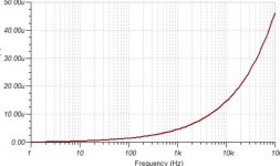
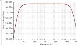
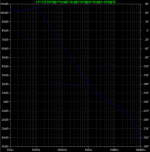
Bellow is S/N for 2.8v output. AD811 may be better but very expensive.

Bellow is S/N for 2.8v output. AD811 may be better but very expensive.
Attachments
H
HAYK
After seen your idea I try to setup an amplifier using AD846. It can take +/-18 Volt. It is CFA.
Last edited:
H
HAYK
This is a source follower not EF, if lateral MOSFETS to be used the opamp can drive them alone.
I made a quick test with lateral MOSFETs, for 33w 1khz 0.007% THD.

I made a quick test with lateral MOSFETs, for 33w 1khz 0.007% THD.
H
HAYK
This is a very simple 1EF amp of QSC type. The opamp is to be TI's headphone CFA chip 6120 (forgot the prefix) as it has higher slew rate and cheaper.
The opamp essentially feedbacks the current of each output. If I don't give any bias, I get just a tiny nonsignificant spick on crossover. To clean it up I give a 20mv bias by feedbacking very slightly 1/100th. It results a bias of 72ma.
I don't think it is necessary to have it temperature compensated.
This circuit requires offset circuit either adjusted or servo.
The draw back of QSC type output is the power supply required to be dual mono.
The opamp supply can be derived from the main, to copy from early QSC circuits but most dual SMPS supplies have an auxiliary +/-15v.

For now, I didn't deal with the stability which should not be difficult to master.
The opamp essentially feedbacks the current of each output. If I don't give any bias, I get just a tiny nonsignificant spick on crossover. To clean it up I give a 20mv bias by feedbacking very slightly 1/100th. It results a bias of 72ma.
I don't think it is necessary to have it temperature compensated.
This circuit requires offset circuit either adjusted or servo.
The draw back of QSC type output is the power supply required to be dual mono.
The opamp supply can be derived from the main, to copy from early QSC circuits but most dual SMPS supplies have an auxiliary +/-15v.
For now, I didn't deal with the stability which should not be difficult to master.
Last edited by a moderator:
H
HAYK
The cost of opamps is an important issue. I started the design with AD844 as I have 4 pieces of it. It is too noisy, much higher distortion and expensive. The AD815 highly recommended by @abraxalito, is excellent choice and DIY friendly, no tab heatsink to solder under, unfortunately obsolete. Mains suppliers don't have in stock, same for AD846.
The TPA6120 is excellent joice it cost 3.6 USD, each opamp has its own supplies good for the IPS, can pour 700ma, more than needed and slew rate 1400v/us.
Tomorrow I will join the two circuit in one using Minek's unusual type using 2x2 TPA6120.
The TPA6120 is excellent joice it cost 3.6 USD, each opamp has its own supplies good for the IPS, can pour 700ma, more than needed and slew rate 1400v/us.
Tomorrow I will join the two circuit in one using Minek's unusual type using 2x2 TPA6120.
Yes.It is too noisy, much higher distortion and expensive
But it have very useful Cz pin as high-impedance output.
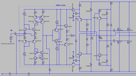
So accurately optimized conditionally-stable amplifier can be built like this:
https://forum.vegalab.ru/showthread.php?t=90971
H
HAYK
It is for that that I have 4 pieces of it. Either the input alone and you get V/I converter 8mS or the output alone with the Z input and you have diamond voltage follower.
If you don't use the output and ground the two Z with negatives tide, you get 4mS symmetrical differential.
If you don't use the output and ground the two Z with negatives tide, you get 4mS symmetrical differential.
Here is another example of similar amp:
https://www.diyaudio.com/community/threads/unusual-amp-from-1987.357369/post-6994032
Original 'The Alexander current Feedback amp':
https://www.analog.com/media/en/tec...tes/58052492001115525484056221917334an211.pdf
https://www.diyaudio.com/community/threads/unusual-amp-from-1987.357369/post-6994032
Original 'The Alexander current Feedback amp':
https://www.analog.com/media/en/tec...tes/58052492001115525484056221917334an211.pdf
H
HAYK
This is the combined circuit. Before I deal with stability, I must model first the TPA6120 as it has no spice model.

H
HAYK
@abraxalito emailed me very helpful info. The THS6012 is very similar to TPA6120. It is the case for frequency response at least what necessary to continue design. As the THS is intended of MHZ frequencies, the distortion, noise are not comparable but it is secondary subject.
- Home
- Amplifiers
- Solid State
- 1 EF AMP
