Hayk, I just realized that 1 or 2 years ago I did build an amp with mirror-vas, kind of like what you are proposing in post #117.
Not the same but close enough..
Here is a link: https://www.diyaudio.com/community/threads/unusual-amp-from-1987.357369/post-7520374
Not the same but close enough..
Here is a link: https://www.diyaudio.com/community/threads/unusual-amp-from-1987.357369/post-7520374
H
HAYK
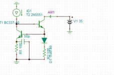
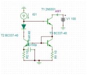
How your are so modest with such a marvelous Minek mirror. I made a comparative analysis with that of Wilson.To make things equal, I used 2n5551 and bc337-40 for both.
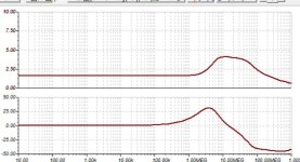
The winer is Minek. The output impedance is 637k vs 558k for Wilson, but most important, if you add a capacitor across the weighing resistor, to flatten the response, with Minek, the phase shift goes back to near zero. See the graphs bellow. I have started to wire the circuit, I will change it to Minek mirror.


Thank you Minek, thank you, thank you very much.
The winer is Minek. The output impedance is 637k vs 558k for Wilson, but most important, if you add a capacitor across the weighing resistor, to flatten the response, with Minek, the phase shift goes back to near zero. See the graphs bellow. I have started to wire the circuit, I will change it to Minek mirror.
Thank you Minek, thank you, thank you very much.
Attachments

H
HAYK
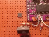
I received the opa2673. It is tiny tiny 4x4x1mm. I am scratching my head how I will solder wires on this chip.
The problem I have is to identify the pins.

The left says top view, the right, bottom. If I refer to the dot on top view, the left row is 1234. If I refer to the bottom view, the dot aligns on the left with 16 15 14 13, not as shown on the above picture which should be mirrored. I suppose the top view is the correct one, isn't it?
The problem I have is to identify the pins.
The left says top view, the right, bottom. If I refer to the dot on top view, the left row is 1234. If I refer to the bottom view, the dot aligns on the left with 16 15 14 13, not as shown on the above picture which should be mirrored. I suppose the top view is the correct one, isn't it?
Attachments
Dot on top and bottom side mouse bite (dent in thermal pad) should be at the same corner.
Those devices are really not intended to be soldered to wires. Pads come easily off and thermal pad cannot be properly used. Performance may also not be optimal due to wire inductance. But good luck!
Here is the bottom view from datasheet:

Those devices are really not intended to be soldered to wires. Pads come easily off and thermal pad cannot be properly used. Performance may also not be optimal due to wire inductance. But good luck!
Here is the bottom view from datasheet:
H
HAYK
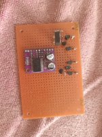
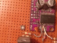
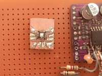
I glued the chip on a small pcb and wired the pins. The -VS, I brought it next to outA to have the magnetic fields canceled as is the case with+VS and outB. It seams there is a substance between the pins thar avoids the solder to short adjacent pins as I didn't had any difficulty to solder. I will add a thick wire from tab to the pcb for better cooling when the glue gets dry.
Attachments
H
HAYK
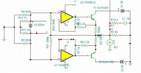
I have added a 10k current feedback and decreased the THD from 0.047% to 0.038%. I investigated further with voltage, current ratios and reached a minima with 1k Rfv and 2.2k Rfi to have it down to 0.03% with ths6012, I tested it on Tina with opa2673, it gives the same decrease ratio. I am not using Cordell models any more as they are optimistic.
I am skeptical with the use of opa2673. I watched on YouTube how people replace this type of casing, hot air blower is a must, it will be an obstacle for a DIY. I am reconsidering to use the TPA6120, the tab can be soldered from the bottom by multiple conducting holes that get soldered resistor leads to make thermal contact from tab to PCB, after all the max dissipation is less than 200mw.

I am skeptical with the use of opa2673. I watched on YouTube how people replace this type of casing, hot air blower is a must, it will be an obstacle for a DIY. I am reconsidering to use the TPA6120, the tab can be soldered from the bottom by multiple conducting holes that get soldered resistor leads to make thermal contact from tab to PCB, after all the max dissipation is less than 200mw.
Attachments

H
HAYK
I did some output IV behavior test with bias 40ma. The Zobel if 100nF, there goes a resonance, 10nF is good. It has 2ohms Zo up to 1Mhz. The linearity is shown with injecting 3Ap 10khz triangular to the output. The crossover zone is shown magnified. The gm mismatch of the outputs can be adjusted by current feedback 2.2k resistors but with what procedure?

Attachments

H
HAYK
I joined the two parts of the amp. A strange oscillations result that start after a certain time. That time can be increased by adding a capacitor between the in and out of the current mirror. I could test the THD for 1w 1khz to be 0.00001%.
It looks much difficult than ad8007 opa2673 combination.

It looks much difficult than ad8007 opa2673 combination.
Attachments

H
HAYK
H
HAYK
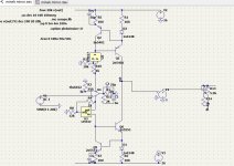
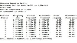
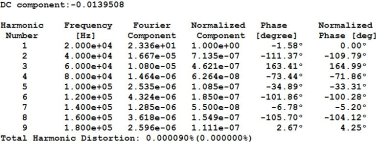
I simplified the compensation to single 15pF. The outputs were oscillating at high currents they were tamed by 22pF capacitors. The THD 20khz 23v got reduced to 0.00007% and the 1khz 23v is 0.000026%.Note that I have a nested feedback 8Mohm.
Attachments

H
HAYK
I saw an interesting way to solder the bottom tab to the PCB.
His idea is to put solder on the tab and the PCB before. The thickened bottom will not sit flat on the pins. One side two pins are soldered so that the chip sits inclined, the PCB is flipped and heated from the bottom by pressing upon the chip and make it sit flat.
The ths6012 DS says the input resistance is 300kohms, but referenced to what? On simulator with unity gain, it measures 13Mohm and the negative ac grounded, 4.8kohm.
I was supposing that the model is wrong and adding 300k to the circuit to the ground which seems to be wrong.
H
HAYK
I have a mysterious phenomenon on LTSPICE. I added a servo on Tina and adjusted to get non resonant servo. I copied on ltspice the same circuit, the amp started behaving as an inverter. You see positive input causes negative output. What should I look for?

H
HAYK
I put aside the servo, it looks the model is not to the spec. as I have input bias current only 0.1u instead of 3u.
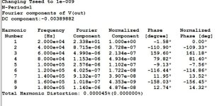
I increased both the open loop gain and stability to have all capacitors 33pF. The THD 20k 23v further decreased to 0.000045%. For now I will leave it as it is.

I increased both the open loop gain and stability to have all capacitors 33pF. The THD 20k 23v further decreased to 0.000045%. For now I will leave it as it is.
Attachments
- Home
- Amplifiers
- Solid State
- 1 EF AMP