H
HAYK
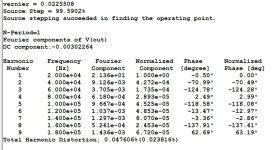
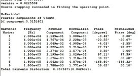
I re tested the opa and output pair by ltspice, with Tina I had 0.43% without current feedback and 0.36% with. On ltspice, using Cordell models I get 0.047 and Onsemi models 0.057%.
If so, I don't need 110db NFB, just 40db is sufficient to get high end quality amp.

If so, I don't need 110db NFB, just 40db is sufficient to get high end quality amp.
Attachments
H
HAYK
I replaced the ad8007 with a symmetrical differential. The problem now the distortion of the IPS+VAS is 0.26% in open loop 20v 20khz. If I replace the transistors with 2n5401,5551, I get 1%. I degenerated the emitters, it destroyed the gain with very slight decrease in THD. My NFB is 55db but in closed loop, the distortion is 0.001% 1w@20khz, 0.009% 21v 20khz, measured on LTSPICE.
Using CCS instead of resistors do nothing good.

Using CCS instead of resistors do nothing good.
H
HAYK
I will start building this circuit on veroboard.
I have the intuition that this simplest form is the most airy sounding due to its single V I conversion that occurs at the input.
I have the intuition that this simplest form is the most airy sounding due to its single V I conversion that occurs at the input.
H
HAYK
Another day another idea.
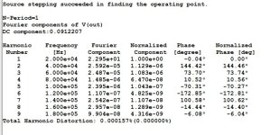
Instead of folded cascode, I am using Wilson current mirror with AD8007. With 40 dB GNFB to be applied, distortion of the current mirror is 0.01% that I suppose it will be less than 0.03% with the AD8007 which got its gain reduced to apply a phase lead. This time the feedback theory worked as it got extra 2 zeros with the 40db GNFB applied to be 0.0001%. To suppose with the output stage that had 0.03% will not exceed 0.0006% 20v 20khz.
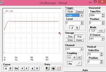
This circuit promises easy to be stabilized, have a look to step response.

Instead of folded cascode, I am using Wilson current mirror with AD8007. With 40 dB GNFB to be applied, distortion of the current mirror is 0.01% that I suppose it will be less than 0.03% with the AD8007 which got its gain reduced to apply a phase lead. This time the feedback theory worked as it got extra 2 zeros with the 40db GNFB applied to be 0.0001%. To suppose with the output stage that had 0.03% will not exceed 0.0006% 20v 20khz.
This circuit promises easy to be stabilized, have a look to step response.
Attachments
Last edited by a moderator:

H
HAYK
I modeled the same circuit with different bc639-640 models on ltspice, instead of 0.01% I got 0.028% but in closed loop it Became 0.00038% instead of 0.0001% in Tina. I replaced the Wilson transistors with ksc3503 ksa1381, I get back 0.0001% on ltspice. I have both pairs, I will measure to see how much the reality diverges from models. The purpose of this thread after all is to be cheap, simple and high end.
H
HAYK
H
HAYK
H
HAYK
The mpsa43 model is wrong. The bf=2.4k is absurd. I found another model more realistic and got the same thd as bc639-640. It looks bf422,423 are similar to mpsa42,92.
I measured with Tina the impedance of c3503 as the DS gives the ic/ib curves. The model is more pessimistic than the DS. If have a look, there is a miraculous 6ma curve that has very high impedance. I will see in real if this is not an accident.
The c2240 a970 is a good candidate if I can cool it by the PCB as its max dissipation is 300mw.
Attachments

H
HAYK
H
HAYK
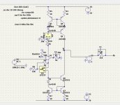
I wanted to understand what makes some transistors better than the others. I find out that the signal current from the supplies are half cycles, as if the output stage in the ad8007 is class B. I replaced it with ths6012 model, it is full cycle. The distortion with bc639-640 lowered slightly but using 2n5401,5551, it got smashed down to 0.00008% even 7 with +/-15v.
On Tina, the signal distortions on the supplies of THS6012, are over 10 times higher than the output.
I have a headphone amp board with tpa6120, I isolated one section to wire it to the circuit bellow and see what I get with very low NFB.
On Tina, the signal distortions on the supplies of THS6012, are over 10 times higher than the output.
I have a headphone amp board with tpa6120, I isolated one section to wire it to the circuit bellow and see what I get with very low NFB.
Attachments
Hi, Hayk!Another day another idea
Well done.
But... Noninverting?
R3 can be an ~order smaller giving +20dB loopgain.
And... Free a few transistors:
https://www.diyaudio.com/community/threads/opamp-common-base.320727/
The main thing is not an amp's core. The main bottleneck is how much MHz your's output stage can pass. Namely there you will place poles and zeros. The gain itself is not an issue, just a dozen of BC850/60 could provide you with ~120 dB loopdepth at 20kHz which is ultimately enough here at DIYaudio.
H
HAYK
Your circuit is similar to #88
Post in thread '1 EF AMP' https://www.diyaudio.com/community/threads/1-ef-amp.405016/post-7511958
What is the problem with non inverting?
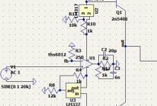
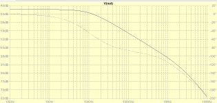
I abandoned the folded cascode as it adds a pole and distortion. By this I am no more Mineks unusual amp series. The Wilson current mirror is great, as it has very high pole and makes very high output impedance yielding very high open loop gain. As shown, just a zero by lead capacitor on the opamp output, it is stable. Of course it will need more elaborated compensation with the output, but it is much easier than with folded cascode.
I may halve the R3 to double the R2 and parallel it with a snubber to extend the open loop response to 20khz. The AD8007 was 100khz.
The TPA6120 that cost $2 can be used for 2 channels instead of 2x$4 for AD8007 and TL072 to be 2 channel servo costs only $0.07. This brings a 2x70w high end amp for less than $25 with original new output transistors.
Post in thread '1 EF AMP' https://www.diyaudio.com/community/threads/1-ef-amp.405016/post-7511958
What is the problem with non inverting?
I abandoned the folded cascode as it adds a pole and distortion. By this I am no more Mineks unusual amp series. The Wilson current mirror is great, as it has very high pole and makes very high output impedance yielding very high open loop gain. As shown, just a zero by lead capacitor on the opamp output, it is stable. Of course it will need more elaborated compensation with the output, but it is much easier than with folded cascode.
I may halve the R3 to double the R2 and parallel it with a snubber to extend the open loop response to 20khz. The AD8007 was 100khz.
The TPA6120 that cost $2 can be used for 2 channels instead of 2x$4 for AD8007 and TL072 to be 2 channel servo costs only $0.07. This brings a 2x70w high end amp for less than $25 with original new output transistors.
H
HAYK
Clearly, i'm missed it.Your circuit is similar to #88
Post in thread '1 EF AMP' https://www.diyaudio.com/community/threads/1-ef-amp.405016/post-7511958
This is mainly because low current source impedance and relatively low output impedance of such a common base output. A workaround is to place constant current source to rails and add third common base BJT with base current compensation.I abandoned the folded cascode as it adds a pole and distortion.
Common mode error without special attention are nonlinear with common mode itself. This provides common mode leak to differential signal and such an effect can't be avoided in noninverting connection.What is the problem with non inverting?
H
HAYK

Yes.I modeled the folded cascode with Wilson mirrors driven by common bases. The result is more gain, lower Fr, and more phase shift at high frequencies.
Now decrease R1 at least 2 orders in a range of tens Ohms. Common base to have high Ft and gain asks for low impedance source . Namely it's current hungry, just a voltage level translation and impedance conversion.
Yes, the main pole VAS load.Does it worth to add so more components?
You already have a high impedance point, it's a best place to put relatively high quality and value impedance and relatively low, stable, clear from parasitics capacitance here.
Say 1 MOhm + 22-33 pF.
This will greatly help for avoiding gain issues due to board leaks, fingerprints and simplify stabilizing of the following EF Triple.
No other OPS could allow such a high fT.
And, yes, try increase order of compensation by adding poles+zeros to keep resulting fT in a range of 10-15 MHz.
And, of course, add at least 1-5 nH inductance of leads, traces, vias, etc in a most connections. Wonderfully descends from simulated heaven to sinful earth.
H
HAYK
Heh... Yes, this is a current conveyor topology developed for.It is crazy idea to increase the VI conversion ratio. This what OLG looks like with R1 20 ohm. It is impossible for my knowledge to stabilize such monstrous NFB.
For your interest here is the my photo from well known crazy competition.
LTspice lacks precision when you're trying to scratch the sky near 300 dB.
But this is voltage feedback, a way-way easy to compensate.
We really need a hint on how to tame such an evil beast, please, let me think some days. Nice thread, demands for brainstorming.
I suppose, most of the gain circuitry can be easily moved in front of the very fast THS6012 output stage to create ultimate headphone amplifier. Moreover, it can be swapped with AD8008.
- Home
- Amplifiers
- Solid State
- 1 EF AMP