H
HAYK
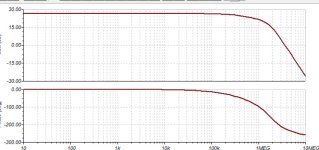
This is the step response but I had to take the compensation from the VAS.

Attachments

Last edited by a moderator:
H
HAYK
H
HAYK
Now I learned better the subject, I will try again in EF mode.
I started by the same output with the opa as driver with bootstraped supplies. For 20Vp 1khz It measured 0.06%. The folded cascode pushed this value to 1.5% at best. So I opted for the current mirror. Bellow 0.15% seems difficult to get.
Instead of applying very high NFB to the output, all I need is less than 60db that pulls the 0.06% to 0.00006%. As I have over 110db I will deal with nested feedback to drive the opa with less than 0.02% and obtain 0.08% at most in open loop. It should be possible.
H
HAYK
I took the IPS-VAS of post 64 Post in thread '1 EF AMP' https://www.diyaudio.com/community/threads/1-ef-amp.405016/post-7503891
Added a nested feedback to leave 60db NFB. I measured 0.001% which is the distortion of the folded cascode with 40db feedback. The distortion added by the ad8008 is negligible. By this I get 0.06% of the output remains the main value in the open loop.
On simulator, when I add in series the two circuits, the protection diodes although not conducting, increasing the 0.001% to 0.02% ,why ? The output although driven by a virtual buffer, increases from 0.06 to 0.1%, why?.Tina is always strange in distortions, even the generator sometimes measures high distortions. I will try again on ltspice.
A diode that’s “not conducting” often is - a very small amount of DC in a nonlinear way, or perhaps a non negligible AC current though it’s (nonlinear) capacitance. It’s for that reason people like to dispense with protection diodes such as the back to back diodes across a diff pair, for instance. But do so at their own peril.
If you suspect that a diode is causing distortion, probe the signal voltage across it and current through it and make sure it isn’t higher than you assume it is.
If you suspect that a diode is causing distortion, probe the signal voltage across it and current through it and make sure it isn’t higher than you assume it is.
H
HAYK
Without diodes, the operating point cannot be established. When I add them without output stage I get the distortion increased although the nested feedback lowers the VAS impedance to less than 50 ohms.
I made the LTspice work with virtual buffers instead of OPA. I had already drawn with simpler folded cascode and used Cordell output models. With open loop and nested feedback, I get over 17V with 1mv input and a distortion on VAS of 0.002% and on the output 0.048%. Cordell models are more optimistic than ONsemi ones.
I will proceed applying over-all feedback little by little to see how my distortion is decreasing in proportion to NFB applied.
H
HAYK
I applied 20db NFB with 10mv input and my distortion passed from 0.048% to 0.006%. Applying 40db, instead of 0.0006 I got 0.0017% and any further stagnated at 0.0015%.
We know that AD8007 is innocent, I tried bd139 140, bc639-640, instead of 2n5401,5551, the same result.

We know that AD8007 is innocent, I tried bd139 140, bc639-640, instead of 2n5401,5551, the same result.
Attachments
H
HAYK
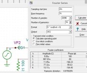
I changed the circuit to a more known type that I have seen it, maybe by Minek. Again my distortion gets limited to 0.015% on Tina for any opamp.. The generator itself measures this number. In fact this number is 0.0001% as the output if I let 0s to sampling start time and both values increase in parallel as I increase until the above limit.
If someone can recalls where such IPS does exist.

If someone can recalls where such IPS does exist.
Attachments
https://www.diyaudio.com/community/...-on-philips-ah578-and-lmk.373773/post-6770986
Driving VAS via op-amp rails will make amp faster (slew rate).
See
https://www.diyaudio.com/community/threads/unusual-amp-from-1987.357369/post-6994032
Driving VAS via op-amp rails will make amp faster (slew rate).
See
https://www.diyaudio.com/community/threads/unusual-amp-from-1987.357369/post-6994032
Last edited:
H
HAYK
Thank you Minek, I was sure it was in that thread but there are so many....
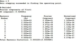
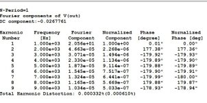
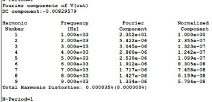
The circuit works fine without compensation with 40db and 46db. This time the distortion is stuck at 0.0003%. I replaced the opamp to LT1056A, 2.4%THD, probably needs resistor on the output.
The circuit works fine without compensation with 40db and 46db. This time the distortion is stuck at 0.0003%. I replaced the opamp to LT1056A, 2.4%THD, probably needs resistor on the output.
Attachments
always interesting to see your modeling progressions
for modeling power devices use no other than MJL4281/ 4302
for smaller TO-92 can also try BC546/556 or KSA992 KSC1845
use tina 546/556 and use on semi 992/1845 models.
I too have had better results using 639/40 instead of 2N5401/5551
in models. 546/556 or 992/1845 usually slightly better.
seems gain/Ft hold up better usually at these voltages/current.
Course in real life voltage handling is limit. But likely slightly better noise/gain
in real life.
H
HAYK
I have simulated the Early Character of power transistors.
Post in thread 'Linearizing the CFP crossover - P3a of Rod Elliot as example' https://www.diyaudio.com/community/...-of-rod-elliot-as-example.402148/post-7441025
Of course the 4281,4302 have high Hfe. The OPA can drive comfortably low Hfe.
Post in thread 'Linearizing the CFP crossover - P3a of Rod Elliot as example' https://www.diyaudio.com/community/...-of-rod-elliot-as-example.402148/post-7441025
Of course the 4281,4302 have high Hfe. The OPA can drive comfortably low Hfe.
H
HAYK
H
HAYK
H
HAYK
If I use another pair of transistors instead of AD8007, I get 0.0012% 1w 20khz and 0.007% for 21Vp.

H
HAYK
I fell upon this interesting on line book about amps to add to your collection.
https://www.google.com/url?sa=t&sou...ChAWegQIHxAB&usg=AOvVaw1jS9clx550bHnzuRGwVjIh
https://www.google.com/url?sa=t&sou...ChAWegQIHxAB&usg=AOvVaw1jS9clx550bHnzuRGwVjIh

H
HAYK
I developed the circuit in more detailed. The bias is temperature controlled by TO220 power diodes fixed upon each output and can be soldered on the PCB. These diodes have low voltage drop, measured 0.520v @10ma. The bias is adjusted by the common bases which got 10 ohms resistors for precise current adjust. The performance remained un changed.

- Home
- Amplifiers
- Solid State
- 1 EF AMP