H
HAYK
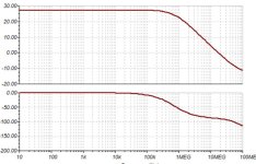
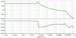
This is a simple 2pole compensation.

Bruno explains his purifi amp to have 90d NFB with -3b @60khz that no analog amp can reach.
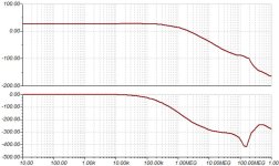
This amp has 118db NFB and has still 112db at 100khz with huge gain margin.
Bruno explains his purifi amp to have 90d NFB with -3b @60khz that no analog amp can reach.
This amp has 118db NFB and has still 112db at 100khz with huge gain margin.
Attachments
Last edited by a moderator:
H
HAYK


H
HAYK
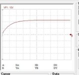
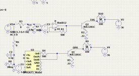
I had doubt about such extraordinary gain. I checked by ltspice the two ths and opa with unity gain and 100kohm source. Both models very far what DS says. To correct, I added a voltage to voltage converter and applied the impedance values of the DS. The distortion also measured for 1v 1khz. It shows the opa has higher gain, better high frequency but distortion of 0.018% vs 0.000005% for the ths that I wonder if it can be real.
PS. The DS of TPA6120 says with G=1 2vpp 1khz 10k load the THD is 112db that is 0.00024%

PS. The DS of TPA6120 says with G=1 2vpp 1khz 10k load the THD is 112db that is 0.00024%
Attachments

Last edited by a moderator:
H
HAYK
H
HAYK
This is the driver and output transistor common emitter response of the circuit above.

The opa has 4 times higher frequency for phase reversal. I can have better chance to succeed with opa2673. To consider also that my modest scope cannot reach to such frequencies.
The opa has 4 times higher frequency for phase reversal. I can have better chance to succeed with opa2673. To consider also that my modest scope cannot reach to such frequencies.
H
HAYK
How do you know?
I If you look at the spice file, unlike usual opamp models derived from measurements, these are modeled by using the internal schematic using discreet transistors. This makes the simulator to run several minutes to find the operating point only.
Open comp.lib file on#58, you can read the spice models of the transistors used. I gave a single 2n5401 model but ltspice sees multiple.
- AD8007/AD8008 Spice Model
- Description: Amplifier
- Generic Desc: Low Distortion / Noise High Speed Amphttps://ifi-audio.com/wp-content/uploads/2021/11/iFi-AMR-HD-USB-Audio-Driver-5.12.zip
- Developed by: VWC/ADI
- Revision History: 08/10/2012 - Updated to new header style
- 0.0 (06/2002)
- Copyright 2002, 2012 by Analog Devices, Inc.
- Refer to http://www.analog.com/Analog_Root/s...nTools/spiceModels/license/spice_general.html for License Statement.
- Use of this model indicates your acceptance with the terms and provisions in the License Statement.
* BEGIN Notes:
*
- Not Modeled:
- distortion is not characterized
*OPA2673 Dual, Wideband, High Output current Op Amp with Active Off-Line Control
*Rev. A
*
- NOTES:
- 1- This macromodel predicts well: DC, small-signal AC, noise,
- , and transient performance under a wide range
- of conditions.
- 2- This macromodel does not predict well: distortion
[*](harmonic, intermod, diff. gain & phase, ...), - temperature effects, board parasitics, differences
That’s only one of 3 or 4 reasons WHY you don’t get hung up over distortion numbers at this level of simulation.Regarding your distortion simulations neither OPA2673 nor AD8008 Spice model include distortion characteristics. THS6012 Spice model does not have information about model characteristics.
If you want someone to make you a good model for one of those devices you can get some company to. For tens of thousands of dollars.
Oh yeah, and it will execute slower than dog $#** too. It has to be modeled transistor by transistor. Of course after developing an accurate model for the basic process transistor (as a building block) first. They’ll make you sign an NDA. Won’t even legally be able to post results here.
Last edited:
H
HAYK
The distortions of the drivers aren't important as the output transistor's nonlinearty is much higher than the unity gain of the driver.
What saddens me is the AD8007. I am using it in open loop, I don't see a means how to predict the distortion in audio range.
I have a modest Behringer UMC202, it hardly measures 0.001%.
What saddens me is the AD8007. I am using it in open loop, I don't see a means how to predict the distortion in audio range.
I have a modest Behringer UMC202, it hardly measures 0.001%.
The distortion correction ABILITY of the front end is only as good as the differential subtraction in the front end error amplifier. That’s why the pairs need to be matched. IC processes help tremendously but your amp is only as good as the front end really is. How well do free macromodels predict this? Roll the dice and take your chances. It literally is a crap shoot. They literally might not have been LOOKING at CMRR.
H
HAYK
It is not as dramatic as that. The opamps are fully floating with the supply currents shared between them in 100 % differential, no ground currents. That is the sum of the output open loop resistance makes the differential error current, knowing that the negative inputs resistance also summed. So if one is higher or lower by mismatch doesn't effect.
The problem is to predict, what is the ratio the IPS stage adds to the distortion of the output that I measured over 2%. In short, the total distortion of the amplifier is determined mainly by the output stage and the NFB if the IPS+VAS are less that 10% of the total open loop distortion.
The problem is to predict, what is the ratio the IPS stage adds to the distortion of the output that I measured over 2%. In short, the total distortion of the amplifier is determined mainly by the output stage and the NFB if the IPS+VAS are less that 10% of the total open loop distortion.
H
HAYK
To choose the VAS folded cascodes, I made an independent bench and tried out different transistor pairs. The best came out is the bc639-640. For 0.5v output which correspond to 2.5A output, it exhibit 0.0038% 1khz where the 2n5401,5551 is 10 times higher and needs lower current.
To match pair Vbe identical, not the case with the models used here.
The IPS needs to pour 7ua only to provoke 2.5A on the output. The question remains how much the distortion of the IPS can be.

To match pair Vbe identical, not the case with the models used here.
The IPS needs to pour 7ua only to provoke 2.5A on the output. The question remains how much the distortion of the IPS can be.
H
HAYK
I modeled a CFA opamp with discreet components, the output diamond buffer comes from XRK https://www.diyaudio.com/community/threads/jhoflands-diamond-buffer.401231/
I tested in open loop for 7ua distortion 1khz it measured 0.006% but mainly 2nd harmonic. Bellow is the circuit with output grounded before my pad crashed and lost the circuit.

I can estimate the ad8007 to be 10 times lower than this improvised circuit. The IP+VAS distortion of 0.01% worst case to be added to the 2% of the output as total open loop distortion.
What I noticed, unlike differential inputs where the even harmonics subtract, here they add up.
I tested in open loop for 7ua distortion 1khz it measured 0.006% but mainly 2nd harmonic. Bellow is the circuit with output grounded before my pad crashed and lost the circuit.
I can estimate the ad8007 to be 10 times lower than this improvised circuit. The IP+VAS distortion of 0.01% worst case to be added to the 2% of the output as total open loop distortion.
What I noticed, unlike differential inputs where the even harmonics subtract, here they add up.
Last edited by a moderator:
H
HAYK
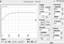
This is the opa with adjusted input impedance. The feedback has 20khz low pass to discard the corrections at high frequencies which makes it simpler to stabilize.
I don't give much importance to phase margins, what is more valuable with simulation Is the transient response as the output stage has different behavior at power than at quiescent .

I don't give much importance to phase margins, what is more valuable with simulation Is the transient response as the output stage has different behavior at power than at quiescent .
Attachments

H
HAYK
H
HAYK
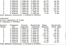
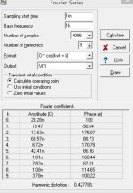
I was using 0.22 emitter degenerators because that how people use it. I had 2.5%THD for 20Vp. I increased to 0.5 ohm as my output's drop out is only this resistor voltage. The distortion decreased to 0.4% with 6db loss in open loop gain.
This is measured on the above circuit in open loop.
Note the phase of odd harmonics are opposite.
This is measured on the above circuit in open loop.
Note the phase of odd harmonics are opposite.
Attachments
H
HAYK
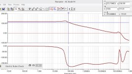
I want to show you something new in stabilizing technology. I post again the loop gain of #61

I was wondering what is this miraculous phase advance that I get which is making the circuit stable. Guess what, my amp unlike an EF, the VAS is opposite phase to the output. When I apply a global feedback alone, it will oscillate, when I apply VAS to input feedback it will also oscillate but of opposite phase. When I apply both oscillating loops, they neutralize each other. What you see a sudden decrease in phase shift is the oscillating internal loop.
In short, If you want to design a stable amp, design double oscillating circuit.
H
HAYK
From theory to practice, I created double oscillating loops one by feedbacking the output current and compensating leaving 83db NFB for the output voltage loop and I get very easily 80°PM. Note, I don't have lead capacitor.
I have added a pair of 10k current feedback to decrease from 0.43% to 0.37%,. 10Mohm current feedback brings it to 0.01%. The voltage distortion measument always not working bellow 0.02%.

I have added a pair of 10k current feedback to decrease from 0.43% to 0.37%,. 10Mohm current feedback brings it to 0.01%. The voltage distortion measument always not working bellow 0.02%.
Attachments
- Home
- Amplifiers
- Solid State
- 1 EF AMP