MXR headphone amp(i need help)

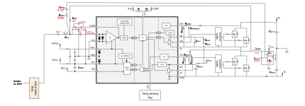
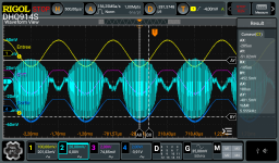
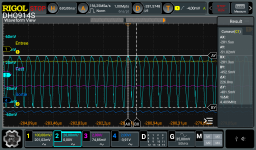
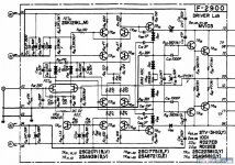
I tried to simulate the mxr circuit with the pspice, but the results don't seem to come out as I thought, so I'm going to ask a question. The closer the original volume resistance is to zero, the bigger the waveform should be
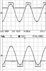
It's true that it gets bigger when it's actually simulated, but the output signal is too low compared to the input signal, so I don't know what the problem is

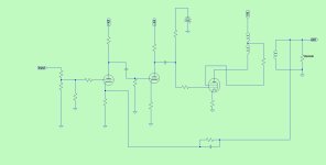
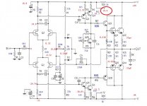
I thought I drew the circuit diagram wrong, so I redrew it, and the results were the same.

I think it's an opamp problem, so I changed the opamp, but the same result came out
What's the problem?

1700321956741.png


1700321942437.png


1700321991939.png

Adding a rear-firing tweeter to existing speakers

I have a pair of DIY Amiga MT speakers made from a parts-express kit that I am sure many of you are familar with.
If not they are a 2-way, ported, floor standing using a 7" woofer and the Peerless DX25TG59-04 tweeter.
This is their crossover:

1700082152304.png


Basically I would like to use them to play around with the concept of a rear-firing tweeter. See if it matches my room and my taste...
But I have a few questions before I go tearing my speakers apart. I am very much a beginner to all this so please correct me if I am making any bad assumptions.

Driver: Duplicate the existing tweeter?

Physically: where to mount the rear tweeter? On axis with the primary front tweeter? Top mount?

Electrically, what is the easiest way to integrate these into the existing crossover? Presumably an L-Pad and a switch to disable them would be a good idea?

Interested in your thoughts as well to this idea but keep in mind its just an experiment.

LJM L12-2 New build Need a guide

Since have an good quality 500w smps from failed Dclass project laying around for some time. Now I want to use it to built HQ amp with xlr inputs that would be used both for home-FI use and small parties like birthdays and so..

Supply is +-55v
Looking for stereo amp, but if it could be made so can be used in bridge mode too, it would be great.
Also would like to use all quality components.
Am going to buy those in a kit so please recommend supplies in EU if think I should replace any.

Here is a link of supply.
https://connexelectronic.com/product/smps500rxe/

Unbalancet to balanced xlr kit.
https://a.aliexpress.com/_mrhkBLI

Protection module.
https://a.aliexpress.com/_ms8PWj2

L12-2 kit.
https://a.aliexpress.com/_mLMe1uC

Enclosure and heat sink would weld out of aluminium.

AMC CD8 Restoration

Dear diyAudio

Greetings! Long time lurker, first time poster.

Background:
Previous owner said it cannot read disc, and said even the disk is not spinning. Upon receipt, I proceeded to clean the lens, lube the spindle motor and also the sled rails (sewing machine oil - I dabbed some onto a cotton bud, and then wiped it on the rails). Laser assembly is KSS-210. Plugged everything in and started it up with a CD (~41 mins, early 90s, John Lee Hooker). The CD spins, but it took a long time (~60s) to read the TOC. Once TOC is up, I played track 1. It plays, but with a fair bit of distortion (like dirty vinyl?). It also mistracks somewhat, and finally gave up (back to TOC) at the 2min mark.

2. I then pulled out all the ribbon connectors from transport to board, cleaned the contacts and reconnect. At this point, the lens did not hunt (and hence, no spinning of disk). Stumped, I tightened all the ribbon connections and now it does read the TOC and plays. [ribbon / connectors faulty, cold solder?]

I noticed the playing is smoother, albeit with 1-2s skips, and I can get it to select all the tracks in the CD (all 20). Interestingly, the longer I allow it to run, the distortion seems to get lesser. It did refuse to recognize longer CDs (>60 mins). Newer, louder CDs (post-2000) under 60 mins can be recognized, but the distortion was so harsh it was unlistenable. It sounds like it was clipping?

3. On close inspection of the board, C503 and C504 are bulging. C208 and C209 are suspect too.

At this point, what would be my next course of action?

1. Change out the suspect caps?
2. I have a scope, so attempt tracking / focus adjustment?

Attached is the service manual, and a couple of videos to demonstrate the sound quality in a downloadable link. https://fileport.io/9XpST5wy4bhp

Thank you!

Should I connect all power supply ground together?

As above. I'm just unsure if it's safe to connect the ground if the 2nd diagram to ground if the first diagram (which are basically the transformer secondaries).

So I got 2x of this supply. (2 separate transformers with dual secondaries each. The 2 wires from the 2 secondaries were connected to make center tap)

Screenshot_20231120_001037_Chrome.jpg


And 2x of this supply. (1 transformer with dual secondaries. 1 secondary for each bridged rectifier)
IMG_0056.jpeg

Thanks in advance.

Danley finally condescends to home market? TDH-3 & c

I've been away awhile. Pardon if this has already been posted. I did a quick search and saw nothing abou them. Seems DSL has added some new smaller speakers to its range. Website is broken right now, so all I have for reference is Sweetwater (where I saw them listed.) Although part of his studio line, these are, I believe, the closest to a "normal" home hi fi speaker DSL has produced to date, and only slightly into the four (rather than five) digit range. See, Tom? Not so hard. You've done well to branch out from marketing to pro audio, stadiums and the ch- ch- chur- 😱er, buildings with the funny shaped plus sign on the roof 😈

Now all you need to do is produce a six digit range, in rare woods, with exotic drivers and crossover components made with precious metals, with capacitors filled with the blood of unicorns and inductors hand-wound by virgins under the full moon in the enchanted forest. 😎

Specs look nice. I'm sure they're nice speakers, but I'm quite content with my pair of used SH-60 at the same price. Granted a bit overkill for a living room, but after six months, I've no complaint (unless you count not finding a buyer for the pair of SM80 collecting dust to one side. Oh very well, luxury problems I suppose. ) 😡

https://www.sweetwater.com/store/detail/TDH3--tom-danley-tdh-3-3-way-passive-loudspeaker

First Watt Clone/ACA/Akitika for a first time builder

I really want to try my hand at building an amp for myself. I can solder and I should be able to competently stuff a mildly complicated board. It just seems like a project I will want to do until I try it. I felt the same way about recapping and rebuilding a few older speakers. I just wanted to see what all the fuss was about.

I have done a lot of reading here and elsewhere to get to this point. I have a few decisions to make so I am here looking for advice and comments. I would be pairing the amp I build with a 1 year old pair of Zu Audio Omen Dirty Weekend mkII speakers. These speakers are pretty efficient and they feature a nearly full range driver with a super tweeter crossed at 12k. Right now they are being powered by an Adcom GFA-535 that my wife found in a thrift store a few years ago. I really like the way they sound, but I can't help thinking they would sounds much better paired with a better power amp.

I recently read through Paul McGowans book about stereo setup and after moving my DWs around I am convinced that I am still a long way from getting the best out of them. This amp will just be the next step along the way.

I listen to just about every type of music, but spend the majority of my time with mellow electronic, jazz or rock and roll playing. I would use a combination of input and would be able to choose between an Anthem TLP-1 or Yamaha WXC-50 as a preamp to start with. At the moment the Zu Audio DWs are in my office (13x11), but I may look to move them into another larger room as I think they need more room to breathe.

I was trained (many years ago) as an electronics technician (aviation) by the Navy so I remember enough to be dangerous. While I still work in the field, I have not worked on gear directly for a few decades. I have a decent soldering iron and all the basic tools and supplies that should be required.

The reason I am thinking about a build for my DWs is all my other speakers require a LOT more power. Both other sets are currently getting at least 200w. I could look for something to build that puts out that kind of power, but it seems more dangerous and potentially much more expensive. I may get there someday....

I am looking to the First Watt clones or Amp Camp Amp because both are well established, well liked and seem like they are potentially a great match.

I did run my DWs on a flea power AppJ tube amp and the sound was great. I have experienced what the DWs can do with just 3w. I imagine 25+/- watts from a carefully designed class A nelson pass design would be pretty good.

The ACA looks to be a pretty simple and was designed to be put together in an afternoon so I imagine it would be the easiest option. The kit comes with everything I would need and the cost is relatively low. My main concern is I will get it together and find that my apatite is only wetted and I immediately want more...

In the same price range is the Akitika GT-102. I am not a fan of how it looks, and it looks like a very different animal. Not necessarily better or worse just a different direction.

Looks to me like the aleph J or F6 would come in under $800 so I guess another question would be if there is something else out there for that cost that should be on my short list?

Questions and comments are welcome. Thanks for reading!

Calculate Total System Impedance

Hi all,

Sorry in advance if something similar has already been posted.

Long story short, I have a couple of new sub cabinets which I wanna set together with another two-way speaker in my living room (for the time being I will only set 1 sub and 1 two-way top). Anyways, I was doing some calculation to see if my amplifier is up to the task but I'm worrying the overall impedance comes out to be 2.66 Ω, while my amp can only support 4-8Ω.

What confuses me is the role the passive crossovers play in the calculations. I feel like this is all in parallel right? is there any way I can sort this out without aving to get a second amp?

The amp I'm using is a digital Kam KXDR 1600.

here is a simplified schematic of the connection (Mind I'm only using one output channel on the amp set in mono).

Thanks in advance.

Scheme-it-export-New-Project-2023-11-19-18-30.png

Hiraga Super 30 droning hum

Having an issue with my Hiraga Super 30 Class A amp.

Had a small hissing sound, so rewired the signal in wires, and the speaker out wires. Also removed the speaker protection boards as I was concerned the small/cheap 12v transformer was causing the hiss. Redid the ground wires as well.

Now, I have a loud droning hum when connected to my Cary preamp.

With nothing plugged into the Hiraga, it’s virtually silent. When I plug my MP3 player into it, no hum. But, when I plug the Cary in, it drones like crazy.

When I plug the Cary into the Sony VFet amp, no drone. When I plug the Cary into my Adcom GFA 545, no drone.

What the heck us going on?

Any thoughts would be greatly appreciated!

P

News from Feastrex Japan

I just received some new pictures for their new development!!
Anyone any idea??? 😀

An externally hosted image should be here but it was not working when we last tested it.


An externally hosted image should be here but it was not working when we last tested it.


An externally hosted image should be here but it was not working when we last tested it.


An externally hosted image should be here but it was not working when we last tested it.


An externally hosted image should be here but it was not working when we last tested it.

Digitize lp records problems

I have digitized hundreds of lps with audacity and Spin It Again, but now the feed from my turntable is intermittent. I thought it was an electronic issue in my audio Techniques turntable so I bought a new Ion turntable with on board speakers . Lps play fine but when coupled to my pc to digitize the sound is intermittent. I'm not an electronics brain so I'm in need of help. Any ideas would be appreciated.

Optimum membrane area for natural reproduction of vocals?

I have made a few 3-ways with nice, robust drivers, and with those type of drivers I prefer 2nd order acoustic filters. Regardless of the speaker's size and sound level, and regardless of how each driver is constructed and implemented, it appears to me that there is always a connection between the Sd/Hz and the speaker's ability to reproduce natural and recognizable vocals. It has often surprised me how the optimal crossover – for me – ends up ½ octave higher than I had expected, based on what is recommended crossover for the drivers on various forums, as if a larger Sd alone adds "something" critically important that makes vocals "more correct". Difficult to describe.

Anyone with similar experience? Pushing tweeters and midranges too far down in frequency, … a bad habit?

I can mention some examples of crossover for drivers that I know well; my choice, and typical forum-recommended crossover which is ½ octave lower:

OWI 5000Hz (3600Hz)
Millennium 2800Hz (2000Hz)
MDM-55 1400Hz (1000Hz)
Seas MCA11 800Hz (500Hz)
AT 15H 500Hz (350Hz)

How far down a driver should be pushed depends, of course, on how the driver below it performs in its upper working range. A light, quick and clean-playing woofer can push the crossover reasonably high. And a light and quick midrange can push the crossover higher than “expected”. In any case, my point is that the speaker often sounds better when the midrange and lower treble get a slightly larger Sd than was originally planned for.

Perhaps they knew what they were doing, the gurus in the 60s/70s who believed that vocals on radio and TV sounded best when the entire midrange was covered by a widerange 8". Perhaps it is not just out of consideration for the lower octaves that todays high-end fullrange drivers are 8"?

In my old days, I have gained increased respect for vintage speakers with a typical 8" woofer, 4" midrange and 1.5" paper cone tweeter, low order cross around 1000Hz and 5000Hz. They can't play loud, but they can reproduce vocals with terrifying realism and clarity.

Opinions?

GK 800RB Help request! (..yes, another one ; )

Greetings, I received a GK 800rb from a friend recently and although I've repaired a number of solid state bass amps, I've got questions about this one. When I received and opened it, and looked at the power supply board it was obvious something odd was going on. The PS board is the 206-0048-C version - and R3 (10 Ohm) was toast (see pic), also Q3 (MPSA56) had it's face blown off and Q2 (MPSA06) was inoperative.
I pulled and checked every component on the power supply board except the six 1000 uF/100V filter caps.
R1 & R2 (56K Ohm) tested spot on,
C1 & C4, C2 & C3 all tested fine.
I pulled and tested rectifiers KBPC603 & KBPC 2502 and they tested fine.
I pulled and tested the four C5 - C7 (470uF/63V) caps and all tested good.
I replaced the burnt R3 and it's pair R4 (10 Ohm)
I replaced the defective Q2 & Q3 pair (MPSA06/MPSA56)
I also replaced 16V Zener diodes D1 & D2 with new and also replaced Q1 & Q4 (TIP31c - [B.C.E.] installed) because of what I saw when I opened this amp.
In the pics submitted you can see where someone had attached the -15V (Red) supply wire directly to the emitter of Q4! And even more odd was that when I looked at the underside of the PS board, where the -15V wire is labeled on top of the board to go, it doesn't look like anything had ever been soldered there! After checking the schematic and looking at pics of other 800RBs I decided to put it where "it's supposed to go".
It's at this point where I could use some advice (at least)...
Having read possibly all of the GK800RB threads here on DIY I decided it was probably prudent to isolate the PS aboard before troubleshooting further. My question is this - as you can see in the pics I've disconnected all of the PS feeds to the amp board: Y/Or/P*/R/Bk (*the board says brown but it's purple on mine) and the Red -15V and the purple +15V supply wires with the molex plug is hanging off the side. Note: the black ground wire in the disconnected +/- 15V supply plug is still connected to one of the output jack sleeve/chassis connections (and I'm not sure if it should remain there during isolation tests)
Question: Is it correct that the Black wire on the board (the two secondary center taps) be disconnected also? Or should the Black wire be left in place to provide the ground when the amp while testing? And if this is the case, and it should be left in the PS board, does the entire rear of the amp actually need to be placed (screwed) back in the amp chassis during testing? Note: the other end of the black wire is connected to one of the output jack's sleeve/chassis connections also.
So, it's a "what's the correct way to isolate the PS for testing the PS board in the 800RB?" question. I've added the other info to illustrate my reasons for doing what I've done so far and the questions swirling around in my head currently.
Well, that's where I am right now. I'm awaiting further instruction in the troubleshooting of this amp from those that know more than I do.
All assistance and insight is appreciated. Thanks
Mark

Attachments

  • 1.jpg
    1.jpg
    94.9 KB · Views: 210
  • 20.jpg
    20.jpg
    196.3 KB · Views: 182
  • 21.jpg
    21.jpg
    216.6 KB · Views: 175
  • 11.jpg
    11.jpg
    249.4 KB · Views: 219

What are the differences in a buffer, line-stage, pre-amplifier and front-end

Reading posts and looking in the diyAudio store there are references to buffers, line stages, pre-amplifiers and front ends. While they seem to have things in common, I think the specific terminology indicate that there are differences, i.e., they aren't just different names for the exact same things.

So:
1) Could someone explain the differences between the devices listed above?
2) In what circumstances is one more applicable than another?
3) I know there are some headphone amps that are used as pre-amplifiers. What characteristics would make the use of a headphone amplifier acceptable as a preamplifier? (For example, maybe a certain gain of the headphone amp would make it unsuitable, or maybe some characteristic of an amplifier would make most headphone amps unsuitable).
  • Like
Reactions: Auld Gravy

Serial 16 ohms or Parallel 4 ohms?

I'm building a pair of ripole subwoofers with 2x 12" speakers and I'm getting to the point where I have to make a decision on whether to wire them in series or parallel. They are Peerless/Tymphany 830669 speakers rated for 8 ohms so the amp is going to see either 4 or 16.

The amp is an XTZ AP100 which is rated 2x110 W @ 8ohm, 2x180W @ 4ohm. I don't really care much about SPL, as the maximum level I'll be listening will be below 85dB and they'll be supplementing 2 Quad ESL57's running on a Quad 303 amp and I expect to cross at about 70 Hz.

Is there any advantage in wiring the speakers in series vs wiring them parallel?

Help with I2S input on an aliexpress PCM1794 DAC (Static)

Hello,

I purchased a PCM1794 DAC from Aliexpress, and when using their bundled LHY AUDIO Coax-to-i2s converter board, it sounds wonderful

However, I'd like to feed it i2s directly via hdmi cable from my DDC/Reclocker - but when I try feeding it i2s directly, I get mostly static. The static goes away when I grab and hold the i2s lines, so I know they are hooked up correctly.

I've been doing some reading of posts that have been posted over the years, it seems like some people say it's transmission line effect, and some people say it's due to reflections

I have two questions:
1. why does it work perfectly when I use the i2s output of the LHY AUDIO board? (the wires are the same length)
2. can I just solder in some 10 or 35 ohm resistors on the destination end (DAC side) of the wires? (I know that everyone says to put the resistors on the SOURCE side, but in my case the source is a DDC/Reclocker that sends out i2s over HDMI so I cannot do that)

Also I've read that people say you should alternate ground wires in-between your i2s lines, but how can I do that in this case, since the inputs are jumpers on the DAC board?

Thanks for any help you can provide,

-- Mike

i2s_1794.jpg

BOSE Model 360 Music System - actually Manufacturer of the Turntable wanted - maybe close to SANYO TP-92S/CEC BA-300 (BA300) ??

Attachments

  • BOSE Model 360 Music System OWNER's.pdf
    BOSE Model 360 Music System OWNER's.pdf
    4.7 MB · Views: 106
  • Bose 360 Turntable top-II.jpg
    Bose 360 Turntable top-II.jpg
    281.1 KB · Views: 146
  • BOSE 360 turntable  lid hinge-II.jpg
    BOSE 360 turntable lid hinge-II.jpg
    366.7 KB · Views: 102
  • BOSE 360 turntable platter.png
    BOSE 360 turntable platter.png
    241.2 KB · Views: 102
  • BOSE 360 turntable motor pulley.jpg
    BOSE 360 turntable motor pulley.jpg
    58.8 KB · Views: 94
  • BOSE 360 turntable tonarm weight.png
    BOSE 360 turntable tonarm weight.png
    181.7 KB · Views: 98
  • BOSE 360 turntable platter-III.png
    BOSE 360 turntable platter-III.png
    228.1 KB · Views: 92
  • BOSE 360 turntable lift+start.png
    BOSE 360 turntable lift+start.png
    186.4 KB · Views: 101
  • BOSE-360-turntable-lid-hinge-III.jpg
    BOSE-360-turntable-lid-hinge-III.jpg
    268.2 KB · Views: 100
  • BOSE 360 turntable  lid hinge.jpg
    BOSE 360 turntable lid hinge.jpg
    216.1 KB · Views: 101
  • Bose 360 Turntable 33-45 switch.jpg
    Bose 360 Turntable 33-45 switch.jpg
    13.6 KB · Views: 96
  • BOSE 360 turntable rear sticker-II.jpg
    BOSE 360 turntable rear sticker-II.jpg
    7.1 KB · Views: 91
  • BOSE 360 offer.jpg
    BOSE 360 offer.jpg
    669.1 KB · Views: 86
  • BOSE 360 turntable unp.-***'y instr..jpg
    BOSE 360 turntable unp.-***'y instr..jpg
    99.1 KB · Views: 96
  • BOSE 360 turntable owner's Cover.jpg
    BOSE 360 turntable owner's Cover.jpg
    70.8 KB · Views: 93
  • BOSE 360 turntable rear Owner's m.jpg
    BOSE 360 turntable rear Owner's m.jpg
    130.2 KB · Views: 87
  • BOSE 360 turntable rear sticker.jpg
    BOSE 360 turntable rear sticker.jpg
    87.1 KB · Views: 86
  • BOSE 360 turntable rear hinges.jpg
    BOSE 360 turntable rear hinges.jpg
    133.8 KB · Views: 90
  • BOSE 360 turntable rear-II.jpg
    BOSE 360 turntable rear-II.jpg
    69.6 KB · Views: 88
  • BOSE 360 turntable rear.jpg
    BOSE 360 turntable rear.jpg
    86.3 KB · Views: 88

Mission Cyrus one (Tog) Op Amp rolling

I am using a Cyrus one (tog) which has developed a crackle/popping noise. It is only audible when using phono input. I have replaced all the capacitors thinking that it may be a bad capacitor, but the noise is still there. It gets louder as the volume is increased.
I am going to replace the op amps on the board next, but wonder if OPA2604 and perhaps the LM4562 can be considered as a drop-in replacement in this particular case?
The picture included is before the recap. I have replaced 1uf and 2.2uf bipolar electrolytic capacitors with wima mks2.
Any advice would be greatly appreciated.

Attachments

  • 2.JPG
    2.JPG
    66.7 KB · Views: 184

Use of mini xlr connectors on unbalanced input / output

Hi,
I want to connect a preamplifier to an amplifier. The two devices (made by myself) are unbalanced and equiped with "ground loop breakers". To avoid problems with noise, humm and buzz I think it will be a good practice to use "mini xlr" elements to connect these devices. The shield will be connected to the chassis of each device but not to the reference wire. One wire for the signal and another for the reference source (connected to the ground's output / Input modules) will connect the two devices. The ground's modules are all connected by a star wiring to the "ground loop breakers" (2 in the amplifier and 1 in the preamplifier). Can you tell me if you have experienced this type of connection (with mini XLR or standard XLR).
Thank you

DIY portable audio recorder

I want to build a portable, robust SD audio recorder with two channels, 24 bit sample width, 96 kHz sampling frequency, phantom power and sturdy XLR connectors and pots. And high audio quality, of course.

As I am not an experienced programmer I thought of using an embedded linux board like the BeagleBoard, a 24/96 codec and a (touch)screen or the circuit of a portable sound recorder like the ZOOM H1 as a basis.

Any suggestions, ideas, comments?


Peter

Cathode Follower Voltage Rails/Headroom in Class B Output Stages

I've never thought too hard about CFs but I'm playing with the idea of DC coupling power tube grids for bias stability on peaks. Since there's now a negative rail the Ak voltage can get big pretty quick so it looks valid to set up a sort of bipolar supply for follower stage. So, I'm trying to work out how big of a positive/negative rail is needed and not excessive. From articles like this is seems that the load line is drawn normally but I'm still a bit perplexed.

Can a follower typically swing all the way to the positive rail as suggested by the load line? Like, If I need to pass a 75Vp signal is a 75V anode voltage (in theory) sufficient? Putting aside for second that the grid signal will be shifted down by the bias voltage. If one was unconcerned with supplying grid current to the power stage could the positive rail be, effectively, 0v since the power tube grid would clamp here as well?

It seems easy enough to determine how close to the negative rail the follower can go but is there a way to determine how low one needs to go into cutoff in a class B output stage? Does it make sense to have a follower capable of reproducing the the entire negative swing when the power tube will be in cutoff at some point? Let's say a -75v waveform peak plus a -50v DC bias, and then another 50 volts of clearance for where the follower's load line crosses 0vgk? -175v?

So, how close can you cut it?

Power supply for Purifi Eval board...

Hi all,

Just wondering about the requirement for the purifi Eval 1 PDR gate drive rail (15v) to be grounded to the main negative rail (nominally -65v). I have a large transformer with multiple secondaries, can I safely connect any nominally chosen wire to act as ground for this 15v line? More specifically I would have the linear stage, so the negative of the linear 15v would be connected to the -65v as ground.... Is that a safe thing to do?

Equally if I have two transformers and two separate supplies, so that one gives me +65/0/-65 and one 15v/0, is is save to connect the ground of the 15v to the -65v, and do I need to be aware of any risks?

In all cases I will be working with linear supplies and transformers, no smps intended.

Replacing IRS with Gate Driver + External Op-amp

Hello everyone,

I am following a reference design from Infineon based on their new IRS2461S IC (attached below). The IC contains an OTA + MOSFET Gate Driver, and I have chosen to replace it with an Op-amp + external MOSFET Gate Driver IC.

My question is whether I should do further changes to the modulation scheme to make it work, or if the modulation scheme will operate as is with the op-amp.

I have also noticed that the capacitor labeled DNP in the attachment is always taken out when switching from (IRS2092) to (IRS20957 + op-amp). Am I correct in choosing to not populate that capacitor for my final schematic design?

Thank you,

Attachments

  • image_2023-09-13_214453885.png
    image_2023-09-13_214453885.png
    29.2 KB · Views: 506

Desoldering compactron sockets

After exactingly populating Pete Millett's Mighty Midget board, I have made a fundamental error and soldered the compactron 6T10 sockets upside down.

We are talking about 12 pin sockets here so the process to correct this error does not seem simple.

I am planning to:

(1) snip the pins on the socket side
(2) order new sockets
(3) desolder the stumps of the pins using a pump and braid
(4) solder in the new sockets with the correct orientation

All with the hope the pads don't lift and I can get enough solder out of the pads to make the room for the new pins.

Does anyone have tips or a smarter approach?
IMG20230818142217.jpg
IMG20230818143342.jpg

QB3/200, any experience with these?

QB3/200 seems to be more or less the same as a 4-65A:

https://tubedata.altanatubes.com.br/sheets/030/q/QB3-200.pdf

I can't see anywhere in the datasheet a recommendation running theses tubes at cherry red plate, but I can't see the usual flash getter on the tubes.
From the Philips DS, there is an example of LF amplification at only 600V / 30mA per tube: 18W plate dissipation at idle.

When looking at Eimac DS:

4-65A.png


But there are operating points like 1000V / 60mA (for 2 tubes) so 30W at idle.

I suppose there won't be any red glow at the plate, from 18W to 30W, right ?

Do you know if it is mandatory to run these tubes at cherry red plate glow? if so, why did they provide these operating examples?

Thank you

Has anyone tried this approach to a "safer" Loftin White?

I found this on the Tube Cad website - https://www.tubecad.com/2015/12/blog0335.htm. It looks interesting and curious to know if anyone has tried this or something similar. I'm still a little unclear as to how the part values (type of NPN, resistor, etc.) would be specified but the approach makes sense.

Might not be in the less is more spirit of a Loftin White circuit but seems to address some potential concerns.

Thanks!

Screen Shot 2023-11-18 at 10.46.11 PM.png

amplifier Leak/Heco 2000 quiescent current help

hi
i own an nice receiver heco 2000(german version of leak 2000).it worked fine but had a loud hum noise(around 120hz).so i've replaced the 2 power supply capacitors.2 decent samwha 10000uf 63v(the original 6800uf 40v).the hum noise there is still but now is very slight.more audible whit low impedence headphones and through speakers(more hum noise from right speaker.
the dc offset is:right: 55mV , left: 75 mV.a little high?
I've set the bias on other amps(whit very clear istructions on service manual), but the process for this heco/leak 2000 is not clear to me as my electronic skills are a bit basic. Can anyone spell out exactly where i should be placing my digital multimeter black-red probes?i've seen where is it the potentiometer vr1(on main amplifier pcb.2 vr1..i presume one for left channel and one for right channel). I've attached the instructions from the service manual.photo of part of service which explains how to adjust quiescent current and 2 photos of electrical diagram.i hope the pages are clear
FireShot Capture 081 - Leak-2000-Service-Manual.pdf - .jpg
1FireShot Capture 082 - Leak-2000-Service-Manual.pdf - .jpg
2FireShot Capture 083 - Leak-2000-Service-Manual.pdf - .jpg

Semiconductor Variance

In my audio journey, I've have come upon the output stage. I have two questions:

1) Is there a discrete semiconductor that doesn't have a lot of variance in production? (I'm assuming there's no 1% tolerant transistor or the like)

2) When it comes to output stage, while chip amps do simplify design, does the cost proposition of them outweigh the performance of a high specced discrete amplifier?
  • Like
Reactions: rsavas

Need helps! Weird signal results on my DIY High-performance Hyrid MOSFET Audio Power Amplifier

Hi everyone,
I may have started my project with to much self confidence. I read the entire book "High-Power Audio Amplifier Construction Manual" from G. Randy Slone. I choose to build the High-performance Hybrid MOSFET Audio Power Amplifier from Figure 11.14. (See first image).
I redraw the entire drawing into the KiCad software (Linux) and created the PCB in the same suite software and have had it manufactured by PCBWay in China. It is my first experience as designing an audio PCB but I have a lot of experience with creating PCBs. I'll attach a picture of my drawing and a PCB capture, as well as some 3D views from KiCad PCB and some pictures of my final PCB. I share those for you to have as much as information to help me.

Now, my first mistake was with the orientation of the two upper MOSFETs. The original figure 11.14 doesn't specify the Drain and Source pin. The only note is the line going to the Gate. The upper MOSFETs have their lines over the center of the part while the lower ones have their lines under the center of the part. Unfortunately, in my software the library have the Source line in the center of the part. So I didn't notice this and even if I rechecked everything two and three times; shame on me, I didn't realized that mistake. It is my first experience with MOSFET, gee... I guess we learn from ours mistakes. Anyway, I was able to use my PCBs by crossing both Source and Drain pins of the upper MOSFETs.

After having fix this, I got the right +VCC and -VCC voltages. I use two Rigol DP712 Power Supply so I can start applying voltages from +/- 5 VDC and going up. But I cannot go more than +/- 8 VDC before the positive section of the Sine wave start to reach a limit as if the +rail limit was reached. Here I don't understand why this is happening when I actually do raise the Power Supply! And the more I raise it, the more the sin wave distord until the output signal goes off. I bet the MOSFET turn off from their internal protection.

I captured some screenshots from my Rigol DHO914S scope. It is a four traces scope. The trace 1 (yellow) is the input signal from my Rigol Generator, a 60 mV,1 kHz sin wave. The trace 4 (Blue) is the output of the Amplifier. The trace 3 (Rose) is the BIAS and finally I used the trace 2 (Cyan) as the testing probe in the circuit. This latest is what concerned me. I trace the signal starting from the Input and as I soon as I reach collector of Q101, I get this really weird signal, an envelop synced with the output signal. So I start to ask myself if this could be due to a very bad PCB design or if it is a result of a faulty part. This is where I ask your help. Maybe some of you are already familiar with this kind of weird signal. I took a zoom of the weird envelop and used the Cursors to measure the frequency and the level. That is the latest capture image; I read -401.5mV as delta Y and a frequency of 4.409MHz !

Any idea what could cause this? Could it be generated by my Drain and Source crossing?
My very best regards,
Yves

Attachments

  • Capture d’écran du 2023-09-21 08-44-06.png
    Capture d’écran du 2023-09-21 08-44-06.png
    58.8 KB · Views: 1,043
  • Figure 11.14 Rev1.0.png
    Figure 11.14 Rev1.0.png
    111.5 KB · Views: 846
  • 01-Figure 11.14.Rev1.0.jpg
    01-Figure 11.14.Rev1.0.jpg
    182.8 KB · Views: 480
  • 02-Figure 11.14.Rev1.0.jpg
    02-Figure 11.14.Rev1.0.jpg
    138.4 KB · Views: 401
  • 06-Figure 11.14.Rev1.0.jpg
    06-Figure 11.14.Rev1.0.jpg
    189.4 KB · Views: 402
  • 20231017_140037.jpg
    20231017_140037.jpg
    385 KB · Views: 425
  • 20231017_140047.jpg
    20231017_140047.jpg
    299.4 KB · Views: 454
  • RigolDS1.png
    RigolDS1.png
    57.5 KB · Views: 453
  • RigolDS0.png
    RigolDS0.png
    50.2 KB · Views: 769

Sourcing old Hiquphon tweeters for Bud Fried's Signature A/6

With reference to these threads:
1.
https://www.diyaudio.com/community/...ver-and-m-a-r-s-system-mystery-repair.405114/

2.
https://www.diyaudio.com/community/...uld-i-change-it-to-parallel-crossover.405233/

I felt that one tweeter was SOFTER than the OTHER - so I used a multimeter but still Measured 4.5 Ohms on EACH Tweeter when each was individually disconnected from the Loudspeaker and connected across a MultiMeter.
So I was under the impression that the Tweeter that was ostensibly faulty is actually NOT faulty. [Since it read 4.5 Ohms in a multimeter instead of INFINITE Ohms or Open Circuit..]

But then I EXCHANGED Faulty tweeter into the non faulty Loudspeaker chassis, and vice versa.
Immediately, I could feel that the faulty tweeter, even though it read 4.5 Ohms, it is playing MUCH SOFTER in the new Chassis.
Thus, the error seems to be in the SOFTER playing TWEETER and not in the crossover.
In the meantime, since David Ellis had mentioned to me on call that the Series Crossover in Bud Frieds designs tends to cook the Tweeter, I went ahead and sourced these :

https://www.ebay.com/itm/374834504920

Feedback on these Hiquphons? They seem identical to what I got inside my speakers, just that the eBay Tweeter listing read circa 1991 and mine in the Loudspeakers I possess, read circa 1996. guessing year of manufacture.

Next steps would be to replace the tweeter
&
Should I replace these 27 year old 10 mFarad Capacitors in the Crossover ADDITIONALLY?

EDIT: Made the Left Speaker the Right and vice versa. The erstwhile soft-faulty tweeter is playing better now, much louder and clearer.

In an interesting twist, almost as if some celestial key has been unlocked, the non-faulty tweeter in the the supposedly faulty chassis (and crossover) is ALSO PLAYING okay.

Need help building speakers for home audio

I have an old kenwood kac-5202 car amp lying around(got it from my father's old car) and was wondering if I could hook some 2 way speakers to its stereo outputs. Saw some people doing this ,I don't have any high hopes for it to be honest but it'll be fun project. Being complete beginner in audio systems , I have only figured out

1)need power supply(at least 12v 15amp)

2)need woofers and tweeters of 4ohm or 2ohm (according to that old manual at 4ohm get 40W x 2, and at 2ohm get 60W x 2, I'm hoping to get to 2ohm so I can squeez 60watt per channel )
manual link : manual

3)need to build a enclosure for 2 way speakers

I tested amp with 12v battery and old 20w woofer lying around and didn't got any noise from amp, things I need to know/understand are

1) speaker(woofer and tweeter) power rating (found speaker power rating in program power while amp manual doesn't mentions any power rating , may be in rms ) ,do I need to match woofer and tweeter power rating ?? or can I use tweeter of power rating much lower than woofer like 4ohm 80watt pp woofer and 4ohm 30watt pp tweeter and use that(amp provide 60w x 2 at 2ohm) OR 4ohm 80watt pp woofer and 15watt rms tweeter (miss match power ratings cause of different brand speakers)

2) woofer sizes matters ? is 6inch 4ohm 40watt pp woofer better than 4inch 80watt pp (much cheaper than 6inch), same with tweeter , I personally don't think I need those big tweeters

3)crossover's. do I need high quality crossover or cheap ones will do(cheap one has crossover somewhere at 4.5khz) , do crossovers changes impedance? and do crossover have power rating?

Converting plate amp to 240 VAC

Hi all,

This speaker plate amp is currently only wired for 120vac operation, I have no instructions on what the primary wires are (on RHS, blue, orange, red and black).

MCM Audio Select, 50-6263 200 Watt Subwoofer Amplifier Module.

Manual for this plate amp is available here: https://www.hometheatershack.com/attachments/200w-mcm-sub-amp-owner-manual-pdf.34129/

Any ideas, or do I need to measure it?

IMG_4053.jpg

NAD 3020 RC Snubber Query

Good morning folks,

I'm looking for reassurance that I've done the right thing or advice if I haven't!

I live in the UK with a 240v 50z electrical supply and own a NAD 3020 which I think sounds fantastic.

A common issue with the NAD 3020 is a power switch with degraded contacts and mine was no exception with the power LED often flickering for the first few minutes of operation.

To rectify this I managed to find an identical replacement. The original switch used to switch both live and neutral, but I have wired the replacement so that both sets of contacts switch the live side only to basically increase the amount of metal making contact for a more reliable connection. The neutral of the mains cable coming into the amplifier is now wired straight to one side of the transformer primary.

The original switch had two blue capacitors in parallel (one in parallel with the neutral switch throw and one in parallel with the live throw).

I read that an RC Snubber (capacitor and resistor in one package) would be a suitable replacement to better protect the switch from
arching, so I bought a Roxburgh RE1201 for this purpose and soldered it in parallel with my new switch.

My concern is having done further reading the encapsulated resistor in the RE1201 appears only to have 1/4 watt power rating according to the datasheet. Is this cause for alarm? I am confused why an item that appears to be specifically designed for this purpose might be unsuitable due to insufficient power rating.

The datasheet is available on the following product page:

https://uk.farnell.com/roxburgh/re1...=AFC-CJ-UK-8989328&gross_price=true&source=CJ

The RE1201 does not seem to get hot and has significantly improved the power on thumps.

In addition to comments on whether the resistor is up to the job, is the 0.1uf 120ohm combination okay? This seems a common value for snubbers available on the market.

Thoughts gratefully received. There are a lot of different opinions it seems around this sort of subject and the mathematical calculations seem to get quite complex, at least for me.

With thanks
Stephen

There are no references on the web, so what's wrong with this simple setup?

Hi, Please help me understand why people use SRPP, CCDA, cathode follower etc., while not using the attached configuration with two triodes in series and GNF.

This is also the one that when simulated gives me the lowest THD among all the previous ones that I have simulated, the one that has the most linear frequency response and also the highest input sensitivity.

(Let us use ECC83 only, pls)

Attachments

  • ECC83-series.jpg
    ECC83-series.jpg
    47.5 KB · Views: 234

Is it possible to convert this amp to have balanced inputs? (Audio Research VS55, schematic attached)

I will soon take position of a fully-balanced Audio Research LS5 preamp. I know I can use adapters to run single-ended gear, but I was wondering if it was possible to modify my amp to accept a true balanced connection? The schematic is attached. I don't know enough about reading schematics to know if it's doable not.

Attachments

Box design program not working? Advice for Design program for Mark Audios Alpair 7MS drivers?

Good afternoon. So the Program am using this Bass box pro. So I usually never have an issue with designing a box for any driver . Well this Mark Audio driver the Alapir 7 MS looks the worst I’ve seen for a ported box design in years. Is there another program I can use to get the right ported box design? If size wasn’t a problem or concern I would be making a Big is Better box. This is for my Dad. He is going through some heart issues right now. So the speakers I built him years ago are to tall not wide or deep. So I have the wood and all the parts. Could someone please point me in the right direction? I’m looking for a certain size box and that I can play around with the box size to the one I want to build? Thanks Jeff

Easy Slow Start with Directly Heated Rectifier?

I read this yesterday on diyAudio:

For those who do [not] like [a particular directly heated rectifier tube - in this case a 5Y3], only because it does not have delayed B+ . . .
Then add an additional 6.3V filament winding (a rectifier dedicated winding, not for the other tube filaments), and . . .
Then connect a 0.65 Ohm 5 Watt resistor in series from one end of the 6.3V to the [tube's] filament, and the other end of the 6.3V to the other end of [its] filament.

That makes a Slow Start B+.

Is this true and as straightforward as it seems?

I have a 5U4G (actually a Svetlana 5C3S / 5Ц3С) that I am proposing to use (I like the coke bottle shape and its voltage drop suits, and I have a few) in an RH84 amplifier, using 6P14P-EVs. I may have a spare 6.3V secondary that I could use this way. Is it advantageous for me to do so?

Simon

Help me start my measuring tools

Hello. I want to measure opamps (noise vs R source, Distortion, THD+N), resistors (noise), PSU (noise) and Tube amplifier (Noise and distortion).

I have :
  • 12bit 2channel Oscilloscope (60MHz)
  • 12bit 2channel Function generator (up to 25MHz - 200MSa/s sampling rate)
  • 2 Bench PSU (I link them together for -+15VDC)
  • Behringer UMC404 Soundcard (24bit/192Khz)
  • EDIT : I already have 3 handheld multimeters 😉

Am I good enough, what do I miss ? I need and uln amplifier, but what else ?

Right now I am looking to make measurement PCB in Kicad for opamp, measurements.
The journey is exciting !

Can i mix a 2 ohm subwoofer with my 8 ohm full range drivers?

hello!

i have an amplifier (50W x 2 +100W), 2 full range drivers (8ohm) and subwoofer (2ohm). i want to know if the sub is compatible and how to set it up. currently, when i connect the subwoofer through its integrated amp, the subwoofer has very low volume.
the amp has a phoenix connector with 6 ports (4x ports for left and right, 2x ports for subwoofer).

AMPLIFIER
Maximum 50W x 2 +100W powerful output
power input: 12V-24V/DC in
speaker impedance: 4-8Ω (Stereo)/2-4Ω(Sub)
speaker power:
2x50W@4Ω + 100W@2Ω BTL load at 24V
2x30W@8Ω + 75W@4Ω BTL load at 24V
2x22W@8Ω + 48W@4Ω BTL load at 19V
2x15W@8Ω + 30W@4Ω m BLT load at 15V

2 full range drivers:
Nominal Impedance 8 Ω
DC resistance, Re 6.0 Ω
Rated power handling* 40 W

Subwoofer: (i legit found this on my stoop to be thrown away and saved it, this is link to alike system)
2 ohm (found on back of woofer driver)
110-220V 60Hz AC
Power rating: 70W
Power: 110V 60Hz AC

please help me, is this woofer compatible with my system? why is it so low in sound? can/should i connect the driver directly to my amp (i would have to cut the chords currently connecting the woofer to the woofer's integrated amp)?

oh and the power chord connecting my amp to the wall is this , but i tried it also with a 19V power chord and the same soft volume issue pursued.

Better Audio by UHF/RF jFET Replacement (<5pF) for 2SK389/2SJ109+2SK170/2SJ74

Better Audio by UHF/RF jFET's/MOSFET's Replacement for 2SK389/2SJ109 and 2SK170/2SJ74 (<5pF) ?

Is the use from the extremely popular Toshiba's complementary Dual jFET's 2SK389/2SJ109 and single jFET's 2SK170/2SJ74 really a good choice (e. g. for a so called true complementary input differential amplifier stage) ?
For the most developers in audio clearly yes - so I think.
Example is in post #45 under
Pass X250 repair
and
JFET/MOSFET complementary-differential preamplifier
and the attachments.
Particularly the dual jFET's 2SK389/2SJ109 are mainly to find in very expensive power amplifiers.

In the meantime I have strong doubts whether the 2SK389/2SJ109 used both for a single and differential input stages (LTP) were and are really the first choice. I think, there are disadvantages as follow:

1) All are hard to find as NOS from Toshiba
2sk389 and 2sj109 -where
The next best thing to 2SK389 / 2SJ109 ?
2sk389 2sj109 NO FAKE!!!!
Replacement For Toshiba 2SK170/2SJ74

2) Not really low and additional different input capacitance between N-and P channel version
(N-channel approximately 20pF, but P-channel version nearly 100pF (!!), i. e. 5 times more - this means for me no true complementary character).
https://pdf1.alldatasheet.com/datasheet-pdf/view/30769/TOSHIBA/2SK389.html
https://pdf1.alldatasheet.com/datasheet-pdf/view/30517/TOSHIBA/2SJ109.html
https://pdf1.alldatasheet.com/datasheet-pdf/view/30559/TOSHIBA/2SJ74.html
https://pdf1.alldatasheet.com/datasheet-pdf/view/30581/TOSHIBA/2SK170.html

Input capacity of integrated operational amplifiers with good sonic character and jFET inputs are much more low - in case of AD817: only 1,5pF.

Thus jFET's and MOSFETs as follow are the best choice for input stages:
2N5484-5486, BF244, BF245 3-8mS 3-5pF
https://pdf1.alldatasheet.com/datasheet-pdf/view/173154/FAIRCHILD/BF244B.html
BF256 3mS, 1pF
https://pdf1.alldatasheetde.com/datasheet-pdf/view/172151/ONSEMI/BF256A.html
https://pdf1.alldatasheet.com/datasheet-pdf/view/77367/MOTOROLA/BF256C.html
BFR1105 30mS, 2,2pF Vds only 7V max
https://www.nxp.com/docs/en/data-sheet/BF1105_R_WR.pdf
BF961 12-15mS, 1,6pF
https://pdf1.alldatasheetde.com/datasheet-pdf/view/95965/VISHAY/BF961.html

Due the low voltage and the low Gm the approach from Fig. 4.2D in the fourth image and under
http://peufeu.free.fr/audio/memory/memory-4-circuits.html
will be a perfect solution - so I think.
Q1 and Q2 is to replace by the low voltage/low gm FET's mentioned before (R11/12 determines the current flow through the input FET's) and the jFETs J3+J4 in fig. 4.2 D by a high voltage video BjT or two medium voltage BjT like BD139/BD140 in case of high voltage supply (medium power outline TO126) for a cascode configuration - similar to the second stage in fig. 5.7 under
http://peufeu.free.fr/audio/memory/memory-5-vas.html

The co called true complementary LTP input stage like schematic from first image should be to avoid (second and third image shows a solution without p-channel jFET's).

What could be wrong with this consideration?

Attachments

Yet another low-budget EL84 Single-Ended amplifier design...

Greetings Friends! It's been a rough couple of years for the frugal DIY tube scene, tube prices are through the roof, and costs of everything else are up, too. So I've had an idea for a low-cost, simple to build amp that will use the cheap-yet-common EL84 power tubes for outputs, a choice of driver (6N1P, 6N23P, 6DJ8, ECC85) and the EZ81/6CA4 tube rectifier. Edcor XPWR013 power and GXSE15-5K output transformers are used, and a Triad C-14X 6H choke.

For the audio circuit, I have borrowed the "Suzuki" EL84 schematic from Single-Ended.com:
ELF -single-Amp.jpg


and for the power supply, I've borrowed from Matt's Marblewood Amplifier over at CascadeAudio.com:

ELF_Schematic_ps.jpg


with a different PT better suited for these power needs. I've retained the individual caps for R and L OPTs, but both channels will share a single Screen Supply, and Driver supply. (Unless that's not a good idea, only costs a couple more caps to make a full dual-rail supply.)

A simple 12x8x3" chassis can hold all components, and simple P2P wiring keeps costs down and allows for wiring flexibility down the road.

ELF AMP 1.jpg


There's a BOM attatched, not sure how to include it in the post. Any thoughts, criticism, improvements welcome. thanks!

w

Attachments

Babysitter for Papa's Koan

related to http://www.diyaudio.com/forums/pass-labs/174674-papas-koan-papas-surprise.html

anyway - ya all certainly know those pics from Paparoom , always filled with newest junk , which is (junk) also familiar to common greedy boy from own wettest dreams ;
some probably spotted , some not - those nice , handy , cocky wooden platforms , on which small FW hot-babes are pedestaled ;
they probably serve few purposes , of which two aren't least important - better airflow around heatsinks ( carpet is soft and thick) and - nice purpose to spend some junk plank pieces :rofl:

Attachments

  • square-mile.jpg
    square-mile.jpg
    198.2 KB · Views: 4,528

For Sale 4 NOS 6C33C tubes

A while back I picked up 6 of these tubes. I played a little with 2
of them but never touched the other 4. I would like to get $ 120
for all 6 tubes and will pay shipping (USA ONLY ) . The lucky buyer
may find a free gift in the box ( some sockets for these tubes) but
don't ask how many sockets or ask for pictures of them or the free
gift won't be included ! And as I am running short on packing material
I might have to use 6 ot 8 6080 tubes to use up space.
  • Like
Reactions: dubadub

The Class - H Amplifier

Hi everyone,

Apart from class-D , the efficiency in Linear amplifiers could be obtained by converting a Class-AB amp into Class-H amp...

I mean to say in simple words "The Rail Switcher Amp" benefits from the elimination of wasted heat incase of class-AB , by splitting the power rails into 2 or 3 TIERS, and choosing the appropriate Rail according to the Voltage Swing at output.....So that the output transistor has less VCE across it to do the job with less wastage...

I have seen many pro-amp manufacturers Quote that Class-H reduces the current consumption from as much as 30% in comparision to same wattage amp in Class-AB, meanwhile, it also states that the heatsinking requirements are much less than class-AB amp.....

But their are many challenges that must be met in order to overcome various obstacles such as Switching noise, Spikes, Seamless Transition from one Tier to another and so on....

Below are the switching waveforms from a pro-amp in Class-H

regards,
K a n w a r

Attachments

  • class-h.jpg
    class-h.jpg
    85.4 KB · Views: 16,276

For Sale ES 1200 Horns

I have a pair of Joseph Crowe’s ES1200 horns, surplus to requirements. They were made for an idea/ project which didn’t materialise, I have moved on to bigger drivers. They are made from Birch Ply and are as machined, so need some final sanding and finishing. I modified the design as wasn’t confident mounting the drivers on end grain, so I let in a plate of 9mm birch ply on the back to mount the CD to.
They are light enough to post, so will offer them to anyone in the EU and UK. Looking of £250 for the pair, to cover material costs and machining costs
7EBB0B2A-6BA8-4986-8949-5B3721F68871.jpeg.7F3B28D5-45ED-42DA-8D64-1C63986D9651.jpeg

DIY? Where to start? Advice wanted

Hello all!

Just getting bit by the tube bug, and trying to figure out the best way to spend other people’s money on some Christmas present suggestions this year. Have no experience with Hifi let alone tubes, but want to put together a cool, interesting-to-me hifi setup for a small room.

I see highly respected designs all over the place (Tubelab’s SPP for example), but they do not feel modular/cheap enough for a beginner to open one box and start soldering with the intent to discover if they even like tube amps in the first place!

Does anyone have experience with these Douk/Nobsound kits? I recognize these may be sacrilege, etc. but I am tempted by the low price/high modularity while still getting to build it with my own hands.

For the same-ish money, the Tube Cube | 7 offers me a highly-reviewed and low risk opportunity to listen to a good quality tube amp but without the satisfaction of DIY.

Suggestions welcome!

Loud constant thumping noise when I mute the radio or turn the volume down to 0

Hi - really need some help to try to trouble shoot this.

Loud constant thumping noise when I mute the radio or turn the volume down to 0.....sounds like the speakers could blow if left on too long. This happens when I turn on to FM and Bluetooth connection. Also the speakers are making static/hissing noise. Also, makes a popping noise when switching from FM to Bluetooth, USB.....

I have a Camper and the radio is a Jensen JWM22 RV radio that only puts out 6w X 4 ch ..... 2 speakers inside the camper and 2 speakers out side. I’ve connected a small Pioneer GM-D1004 amplifier class D 4 channel RMS of 45w X 4 using high inputs (only option I have). I only connected the 2 outside speakers…..only using 2 of the 4 channels. The other 2 channels are not being used at this time. The 2 speakers I’m using are DS18 ZXI-454 (4x6) with RMS 60w per speaker. The amplifier already has a ground and power wire connected to the wire harness 14 gauge.

I connected a car amplifier to the stereo and it makes static noise that is very noticeable, even when playing music. Without the amplifier it makes very little noise …barely noticeable when the volume is muted. I’ve unconnected and reconnected everything and it still makes the noise. Also, when I turn down the volume to zero or mute the volume it makes a very loud continuous popping and other loud noises until I turn the volume back on. I’ve connected power and ground to the battery and I also tried using a different battery. Also tried connecting the ground to the frame.

Any suggestions on what I could do to fix this?

I would like to add a subwoofer one day for tailgating …my main concern is getting the above fix

1699366560193.png

Boxsim Full System Design from Visaton - Free

Boxsim seems to be a full featured system simulator:
http://www.visaton.de/en/literature/software/downloads/index.html

Up to 8 loudspeaker drivers and up to 6 amplifier outputs with separate filters
Takes account of diffraction at the baffle
Frequency response along the axis and in over 20 other directions
Phase response is calculated separately for each driver
Separate impedance response for each amplifier output
Beaming effect and energy frequency response
Crossover editor with freely configurable component positioning and automatic crossover optimiser
Cabinet variants: enclosed, bass reflex, bandpass, biventilated bandpass
Import of frequency and impedance response from many standard measuring programs (e.g. ATB, Arta, JustOct)

I gave this program a quick try and here are some of my impressions:
- The schematic editor is clumsy being a grid where you choose what component to place - it works.
- The simulator is a bit slow to compute taking about 3 sec after a single schematic value
change to show with a 2 GHz Core2 processor - I should move to my i7 I guess.
Xsim responds instantly with the 2G Core2.
- The polar plots, actual circular ones have such large steps in angle, every 30 deg from
what I see that lobing is most often missed. Is there a place to change the step size?
- Off axis response shown as a family of curves also steps in 30 deg increments which is
also too large.
- Program loads with all Visaton drivers available have not figured out how to add a new
driver with FRD, and ZMA files.
- Predicted phase response looks odd, but probably have to correct for time delay in
measurement files.

Has a lot to offer but all in all Xsim has a better feel to use but lacks many of the features here.

Wharfedale Shelton XP2, A minor classic IMO

God bless my soul, how I love my local charity shop and the random speaker bargains they serve up. 🙂

They had a flippin' random 1980's bargain that even I would take on for £30 this week. For those of you who don't know, Wharfedale had a superb cabinet building shop up in Idle, Yorkshire. Even if the speakers are broke, they are sufficiently solid to be used as stools to sit on round your home. 😀

Enter the Wharfedale Shelton XP2. I had a vague idea that this was a 20L closed box 8" bass plus 3/4" mylar tweeter design. A design about the size of a very big box of Kellogg's Corn Flakes. Which probably meets the WAF criterion.

TBH, they aren't bad for £30. It all works. Good bass response. The expected lively mylar tweeter response in the KEF T27 mold. I am very pleased with them. I was expecting a big roll of stuffing inside the closed box. And it turned up. The crossover completely surprised me. 8 elements!

So far I have counted 2x 1mH coils, two 16uF Elcap NPE caps, and a smaller tweeter coil around 0.3mH and perhaps about 3uF cap. Big surprise is a couple of tiny elements around 33R resistance and 0.47uH. I think this must be a BW3 design with some consideration to RF impedance. Ah well, we shall investigate further this Golden Age of British speaker design.

It sounds excellent for sure. Diana Krall, Kate Bush and Chris Rea all sounding better than on most Android tablets. 😎

Attachments

  • Wharfedale Shelton XP2 External View.jpg
    Wharfedale Shelton XP2 External View.jpg
    101.5 KB · Views: 1,558
  • Wharfedale Shelton XP2 without grille.jpg
    Wharfedale Shelton XP2 without grille.jpg
    74.5 KB · Views: 13,324
  • Wharfedale Shelton XP2 Inside.jpg
    Wharfedale Shelton XP2 Inside.jpg
    87 KB · Views: 4,979
  • Wharfedale Shelton XP2 Crossover.jpg
    Wharfedale Shelton XP2 Crossover.jpg
    87.1 KB · Views: 2,208
  • Like
Reactions: indianajo

JBL LE10H + 2405

Got my shelf a rare find
One pair of LE10H and one pair of 2405 tweeters Both of them are inbox brand new and in perfext shape ....Foams are like new
they have been stocked inbox in a shop never opened
It appears that the conditions there where perfect so foams have absolytely no probs

Intention is to make something like a studio monitor
is this possible ? will these two work nice together ?
Can any one suggest an enclosure design that will be raltively small in size and work well with these units ?
good eficiency is a target rather than a lot of power

Help with Analog Electronic Instrument Sound Quality

Hey folks,
My group and I are working on building a musical instrument using mostly analog circuits and are running into trouble with beat frequencies and sound quality. We're getting some pretty strong beat frequencies and would love some advice from an audio engineer on how we can combat the ****** sound we're getting. Here's some more about our system:
12 555timers in parallel for each frequency -> LM 386 op amp as a signal combiner -> bandpass filter -> (amplifier/filter (https://www.amazon.com/5V-12V-Ampli...words=arduino+amplifier&qid=1700168828&sr=8-3) chip -> 5W speaker. Currently, individual notes are working well but combining 2+ frequencies results in a large degradation in sound quality.

What could be the source of our terrible sound quality when playing multiple notes? I understand that we're amplifying twice, we also attempted to mix the individual signals together by wiring them together directly through 120k ohm resistors. Any thoughts?

Thanks in advance

Kits for LM3886 / LM2876 / LM3876

If offer these kits with the passive components on the hood.de market place :​


https://www.hood.de/i/komponenten-k...erstaerker-lm3886-lm2876-lm3876-113751030.htm

You can build the kits with the LM 3886, or a lower power LM 2876. The latter seems to be more available and is on the TI website too.


E.U. buyers please use this portal. But I can send these to other destinations on request.

P_20221024_184844.jpg
Projects by fanatics, for fanatics
Get answers and advice for everyone wanting to learn the art of audio.
Join the Community
507,489
Members
7,874,148
Messages

Filter

Forum Statistics

Threads
405,575
Messages
7,874,148
Members
507,489
Latest member
bobberhead56