Boxsim seems to be a full featured system simulator:
http://www.visaton.de/en/literature/software/downloads/index.html
Up to 8 loudspeaker drivers and up to 6 amplifier outputs with separate filters
Takes account of diffraction at the baffle
Frequency response along the axis and in over 20 other directions
Phase response is calculated separately for each driver
Separate impedance response for each amplifier output
Beaming effect and energy frequency response
Crossover editor with freely configurable component positioning and automatic crossover optimiser
Cabinet variants: enclosed, bass reflex, bandpass, biventilated bandpass
Import of frequency and impedance response from many standard measuring programs (e.g. ATB, Arta, JustOct)
I gave this program a quick try and here are some of my impressions:
- The schematic editor is clumsy being a grid where you choose what component to place - it works.
- The simulator is a bit slow to compute taking about 3 sec after a single schematic value
change to show with a 2 GHz Core2 processor - I should move to my i7 I guess.
Xsim responds instantly with the 2G Core2.
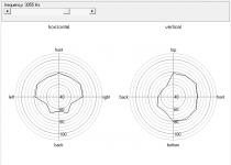
- The polar plots, actual circular ones have such large steps in angle, every 30 deg from
what I see that lobing is most often missed. Is there a place to change the step size?
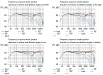
- Off axis response shown as a family of curves also steps in 30 deg increments which is
also too large.
- Program loads with all Visaton drivers available have not figured out how to add a new
driver with FRD, and ZMA files.
- Predicted phase response looks odd, but probably have to correct for time delay in
measurement files.
Has a lot to offer but all in all Xsim has a better feel to use but lacks many of the features here.
http://www.visaton.de/en/literature/software/downloads/index.html
Up to 8 loudspeaker drivers and up to 6 amplifier outputs with separate filters
Takes account of diffraction at the baffle
Frequency response along the axis and in over 20 other directions
Phase response is calculated separately for each driver
Separate impedance response for each amplifier output
Beaming effect and energy frequency response
Crossover editor with freely configurable component positioning and automatic crossover optimiser
Cabinet variants: enclosed, bass reflex, bandpass, biventilated bandpass
Import of frequency and impedance response from many standard measuring programs (e.g. ATB, Arta, JustOct)
I gave this program a quick try and here are some of my impressions:
- The schematic editor is clumsy being a grid where you choose what component to place - it works.
- The simulator is a bit slow to compute taking about 3 sec after a single schematic value
change to show with a 2 GHz Core2 processor - I should move to my i7 I guess.
Xsim responds instantly with the 2G Core2.
- The polar plots, actual circular ones have such large steps in angle, every 30 deg from
what I see that lobing is most often missed. Is there a place to change the step size?
- Off axis response shown as a family of curves also steps in 30 deg increments which is
also too large.
- Program loads with all Visaton drivers available have not figured out how to add a new
driver with FRD, and ZMA files.
- Predicted phase response looks odd, but probably have to correct for time delay in
measurement files.
Has a lot to offer but all in all Xsim has a better feel to use but lacks many of the features here.
Last edited:
I like it. It's very good when you find your way round all the settings. ")
There's another affordable Monacor product that claims to include a lot of driver files, since I find Monacor a bit vague on detail otherwise.
Design Software CAAD-4 2
Importing FRD and ZMA files into Boxsim can be done for other brands, but I do find it all quite difficult, especially since you are never quite sure what sort of baffle or box was used to derive them. Acoustic centres can be adjusted in the SEO setting, and that is extremely useful if time-alignment and driver offset is of interest.
Visaton drivers are really very good IMO. You learn your way round them:
W 200 S - 8 Ohm
There is also a huge databank of existing designs, of varying quality. You just put the file in the "projekte" folder and it becomes available to edit.
boxsim-db.de | Boxsim Projektdatenbank
Perfect for the diy-er.
Attachments
Program loads with all Visaton drivers available have not
figured out how to add a new driver with FRD, and ZMA files.
Hi Pete,
this procedure works for me.
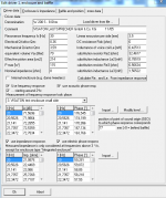
Select new project, Menu "Drivers and Enclosures"
"Driver data" : fill in driver TS parameters until Le (not included),
load frd and zma files by pressing Import, checkpoints (use FR, Imp, phase),
press "calculate Re and Le", OK to calculated values.
"Enclosure and Impedance": define box and tuning
"Baffle and position": uncheck "Common outer housing",
define baffle measures and chamfer
OK to all.
I don't think you can change the resolution on Polar Plots. I agree it's hard to see where the lobe is pointing at crossover with 90 degree phase aligned filters.
It's only a tool, and works based on the assumptions of the modelling. In fact there is a bug in three ways, that the lobing becomes symettrical even if you take out a driver.
I like the way Boxsim can adjust for driver sideways offset and time-alignment. But in the end, you have to listen and adjust the final result. It doesn't calculate wall and room gain in any useful way, for instance. You'd end up with some boomy speakers if you entirely trusted Boxsim's flat response.
A useful tool, but in the end, like all tools, it's only as good as the person using it.
Attachments
@Steve,
you always seem to forget to mention the most important
thing for proper simulation. That would be taking one's own
measurements, in one's own room, in one's own box of
interest.
Simulation is as good as data that is fed to it. In the end, it's
free and it works. It saves ones money needed for experimenting
with different part values.
@Pete,
I can't find anywhere an option to change the step size in polars.
I haven't forgotten measurement at all. I just don't do it.
I know what a flat neutral speaker sounds like with my favourite test music. I also look at most of the classic designs. And circuits and drivers that measure flat often sound horrible. I've never had any luck with 6" drivers and soft-domes, for instance.
We should mention that the Boxsim optimiser is interesting when you run out of ideas sometimes. It has a mind of its own, but sometimes comes up with interesting solutions.
BTW, you can work out lobing easily enough by changing the acoustic centre on the tweeter and seeing where it lines up phase at crossover for maximum reinforcement.
But, of course, it mostly allows me to try new stuff cheaply. Like series filters and BW3. I mean, lets be honest. A lot of the stuff here is all a bit predictable.
I haven't forgotten measurement at all. I just don't do it.
This is exactly the reason why you were not lucky with
6" units and soft domes. Nothing wrong with these.
You just refuse to be cured
.I like you anyway.
Most simulation programs like this one are not intended to simulate room effects, so I don't really consider that an issue. We need to have target responses that take into consideration the intended use (near wall, out in room, etc.).
Have you reported that bug?
I'd say that the circular polars are essentially useless as it is, where if they provided a user set interval it could be very educational with regard to lobing with different crossover types.
Have you reported that bug?
I'd say that the circular polars are essentially useless as it is, where if they provided a user set interval it could be very educational with regard to lobing with different crossover types.
Boxsim is IMO a very useful tool to get the basic cross-over idea on paper and start from there. Most of the time I use one of the Visaton drivers and alter the values until it "looks" like the driver I'm going to use. IME this works pretty good, most of the time when I've build the crossover prototype I don't have to change the capacitor and inductor values much to get the desired response, Boxsim really gives useable estimations.
Nice feature is that it'll show bafflestep and diffraction artifacts and that there's also a very handy tool to calculate the lenght of a port.
For enclosure tuning I use AJhorn.
Nice feature is that it'll show bafflestep and diffraction artifacts and that there's also a very handy tool to calculate the lenght of a port.
For enclosure tuning I use AJhorn.
New user of boxsim here and was wondering. If importing you own measurements would one measure the response of the different drivers in the center of them indevidualy or take one point (listening hight) ?
Somehow I think I'am being misinformed and presume one has to measure alle the drivers in the center, same distance to the baffle and then compensate the SEO. And boxsim will take it from there?
I also don't understand if boxsim schould be able to derive the Le and Re and what not from the impedance plot, doesn't work for me anyhow, get an error dialog.
Great software so far, 'easy' to learn. (much to learn still)
Somehow I think I'am being misinformed and presume one has to measure alle the drivers in the center, same distance to the baffle and then compensate the SEO. And boxsim will take it from there?
I also don't understand if boxsim schould be able to derive the Le and Re and what not from the impedance plot, doesn't work for me anyhow, get an error dialog.
Great software so far, 'easy' to learn. (much to learn still
)AFAIK Boxsim does not support different microphone positions, the simulation always assumes the microphone to be in infinity. Hence the program simply sums up the on-axis SPL response of every driver and calibrates the level to 1 meter.
Imported measurements always should be taken on axis of the individual driver. Even measurements without phase information are supported, but apparently it's not possible then to adjust the acoustic center of the driver (in German SEO), leading to a simulation which is wrong in this respect.
The automatic calculation of Le and Re simply adjusts the elements of the model for the lossy voice coil inductance. These are the last 5 fields of the input mask, where nobody knows what to enter. This option always should be used in order to allow for a smooth transition from simulated to measured impedance response. Otherwise you may get a step in the impedance curve at a certain frequency. The term Re is misleading because it does not at all mean the dc voice coil resistance Re. It actually means the resistors Re2 and Re3, which are wired in parallel to the inductances Le2 and Le3 in the model.
Imported measurements always should be taken on axis of the individual driver. Even measurements without phase information are supported, but apparently it's not possible then to adjust the acoustic center of the driver (in German SEO), leading to a simulation which is wrong in this respect.
The automatic calculation of Le and Re simply adjusts the elements of the model for the lossy voice coil inductance. These are the last 5 fields of the input mask, where nobody knows what to enter.
This option always should be used in order to allow for a smooth transition from simulated to measured impedance response. Otherwise you may get a step in the impedance curve at a certain frequency. The term Re is misleading because it does not at all mean the dc voice coil resistance Re. It actually means the resistors Re2 and Re3, which are wired in parallel to the inductances Le2 and Le3 in the model.These are the last 5 fields of the input mask, where nobody
knows what to enter.
Isn't there a button "Calculate Re and Le from Impedance plot" for
the 5 missing fields?
If I use my own measurements (limp and holmimpulse) on the tweeter and don't want to use the acoustic phase resp. the I get this error:
Error: driver 2: fs, Rdc, Qes, Qms, Vas, Sd must be > 0 or frequency response and impedance response incl. Phase must be completely imported. Le, Re2, Le2, Re3 and Le3 must be > 0.
But if I try to to calculate from impedance plot I get the error:
Error: Gleitkommadivission durch 0
So, I'm a bit stuck Perhaps it's not really important either way, dunno.
Error: driver 2: fs, Rdc, Qes, Qms, Vas, Sd must be > 0 or frequency response and impedance response incl. Phase must be completely imported. Le, Re2, Le2, Re3 and Le3 must be > 0.
But if I try to to calculate from impedance plot I get the error:
Error: Gleitkommadivission durch 0
So, I'm a bit stuck
Perhaps it's not really important either way, dunno.The download link no longer works.
But I was able to find a copy and get it working by using the wayback machine.
Same site also allowed me to get a copy of other software no longer being offered like Xsim.
The link is probably dead because the software has been upgraded to Version 2 which is available from Visaton here.
- Home
- Loudspeakers
- Multi-Way
- Boxsim Full System Design from Visaton - Free