What about LESAHIFI otl

Hi all, I found this (I think new) company from my country making some amps among them this OTL headphone amp, that by type of schematic it seems a middle ground between the bottlehead and the darkvoice. Nothing new under the sun, I ask an opinion about quality/circuit because it doesn't fully convince me. These are the links:

LESAHiFi | Amplificatori, Preamplificatori, Alimentatori, Valvole
[PASCAL GOLD] PCB DIY KIT Amplificatore Valvolare OTL (Cuffie)/Tube headphones | eBay

Channel‐Length Modulation in mosfet datasheet

Hello.
Can you help me understand how to find this information in the datasheet ?
I read a lot of articles from different schools/uni but non of them explain how to find it, beside graphical approximation, and warn it's not precise.

I know that it is modulated by VDS but that's all.

I found out it's also called lambda and can be found in spice models, thanks to Elvee.

Thank you.


example : Channel Length Modulation in MOSFET (VLSI Design) – Buzztech

electric shock when you touch speaker

hi everyone, i recently acquired a old set of final sound 900i electrostatic speakers that have some problems, the main one is when you touch the front of the speakers you get a electric shock, they are powered by a 12v dc power pack and use 300mh, the weird thing is they both do the same thing, anyway does anyone have any ideas what the problem could be, would it be worth fixing them etc, thanks in advance guys....

R25 smokes in tse 300b

My TSE sat Idle for some years because I was having issues with it and and only now getting back to get it running again.

this TSE is setup for 300b tubes.

I powered up with just a rectifier.

b+ 440
b- -175

After some a few min. R25 smokes. I replaced R25 and R14.

Figured I should start out with the proper checkout steps.

Filament voltages were 4.95 each
again b+ 440, b- -175
Grid of right output tube is -58
Grid of left output tube is +350 and slowly climbing

With rectifier in after a few min. r25 starts to smoke again.

I measured across r25 and getting over 600 volts.

So, where do I go from here?

Hifonics BRX 3016.1D diagram

Hello, I have a problem with this amplifier, does anyone have a diagram of the inverter or the whole amplifier?
I have a problem with the same amplifier. The customer himself replaced the inverter transistors and literally burned down again. All items checked. However, the inverter does not work. Looks for IRFP064 control signal too weak. I don't see any burnt path. It is possible that it is hidden under the adhesive or trafo. According to the meter, there is power and GND on the respective legs of the control transistors. If I skip the D669 and D649 transistor driver. The inverter starts.

Upgrading the Op-amps in old Orion amps

I've been doing a lot of research in regards to the possibility of upgrading the op-amps in some of the old Orion amps. What I've found is a lot of people making claims of this or that op-amp is the "best" based upon the data sheets and/or those claiming they can hear a significant change for the better in sound quality. Problem being that most all are completely disregarding the circuitry that the op-amp is to be used in and if that "best" op-amp is even compatible with that particular circuitry. Although there were a few people who actually seemed to know what they where talking about. So... I'm hoping they may see this and offer their advise.

The circuitry in the old Orion amps is basically the same from model to model and all though out all the years of those made in the USA. The op-amps Orion used where the NE5532N or 4562D, NE5534N and LM837N. Any suggestions for upgrades for those op-amps? Especially for the 4562D and the LM837N.

keratherm for mosfets on f6

Quick question, the keratherm has the woven "bronze; looking material and a separate white material - do I use both under the mosfet and if so is the bronze size down on the heat sink and the white material on top of it (under the mosfet) or is the white material just some some sort of backing material that's used during production and I don't use it at all?

thanks

UPS for computer

I have a computer which functions as my firewall, PieHole, router, etc

I currently have a Cyberpower 1500VA similar to this unit:

Amazon.com: CyberPower CP1500PFCLCD PFC Sinewave UPS System, 1500VA/1000W, 12 Outlets, AVR, Mini Tower: Electronics

their specs are total BS since it uses two 9AH 12.6V gbatteries which give a max of 227watts.

At a reasonable discharge one can cut that in half, so maybe 1Hr at 120W.

I'm thinking of ruining wires to a pair of these:

Amazon.com: Deep Cycle SLA Replacement Battery 12V 35AH AGM Battery- Replaces Husqvarna YTH2448 Lawn Tractor Battery- Chrome Battery: Automotive

Which should reasonably support a 120W load for about 7hrs.

Has anyone done something like this?

My biggest concern is the inrush current charging the batteries after full discharge.

Solid State Radio Scott RX-19 RX19 (Blaupunkt) - Schematic wanted

The radio from the attached pictures is death. The reason therefore is a faulty mains transformer (integrated thermal-fuse interupted - I think).
Who know the voltage value behind the voltage regulator ?

BLAUPUNKT: Radio

Attachments

  • IMG_20181214_151426.jpg
    IMG_20181214_151426.jpg
    753.7 KB · Views: 93
  • IMG_20181214_151414.jpg
    IMG_20181214_151414.jpg
    650.1 KB · Views: 95
  • IMG_20181214_151408.jpg
    IMG_20181214_151408.jpg
    845.4 KB · Views: 94

Input to LM3886.

I would like to ask how I should connect the input electrolytic capacitor to LM3886 IC. Searching online did not result in any finds whatsoever. Only one schematic had a properly marked input capacitor. Since an electrolytic capacitor is polarised, I would like to know how this should be connected to the input. The IC's non-inverting input is connected to a resistor chain of two series resistors. The resistor that directly connects to the chip is 1k and the other , 22k, connects to ground. Signals will be fed at the point between these resistors. Which capacitor's electrode should be connected to this point? The input signal will be applied between the capacitor's other terminal and ground.

Can playing playing poor quality records damage my stylus?

I've been away from LP's for 20 years and I recently picked up a new turntable
with an Ortofon 2M Blue cartridge and the replacement stylus is about $175

This may be a silly question but Can playing playing poor quality records damage my stylus?

I do wash any old albums that I've purchased to remove any grime and dirt.
But some are less than optimal (light scratches etc) and I would hate to cause
extra wear on the stylus. My turntable does have a removable headshell so if
need be I could have a second cartridge setup with a less costly stylus.

Thoughts and suggestions?

Thank you

Suggestions for parafeed OPT - Any guidance out there?

I have a small head amp that I have been testing, which currently uses a relatively large 30VA toroid as OPT.

The approximate reflected Z is about 15k, using 300R load to the secondary.

Primary volts swing is about 30V RMS, using the toroid (240:30V) - primary L= 6H and lossy capacitance is a whopping 0.5uF!
Turns ratio comes out to something like 6.7:1

So far I have found Edcore XSM 10k:150 (oversize but tolerant of the voltage requirements)

Hammond 107V, which looks tiny...DIP mount???
But also has good primary inductance, 25k:600R, and appears to be suitable for an input level of 30V RMS.

Thus either OPT above, I am either using a lower Z tap for a higher load R, or vice versa.

Any suggestions, hints or advice, to help me select one of these OPT, or perhaps another more suitable, is gratefully received.

Thanks

Subwoofer mixed impedance question.

I want to use two identical DVC woofers in a single plate amp powered sealed sub enclosure. Each of the voice coils is rated at 2 ohms. If I configure things symmetrically I can get;

0.5 ohms (everything parallel)
2 ohms (coils series and woofer parallel or vice versa)
8 ohms (everything series)

The amp isn't rated for less than 4 ohms. At 8 ohms I leave some power on the table I think.

My question is what would the impact be if I were to wire one woofer's VCs in series, one woofer's VC in parallel and the two woofers in series?

I do not have the experience to guess at the outcome.

What impedance would the amp see?

How would having one woofer running at 1/4 the impedance of the other impact power handling?

If the parallel VC woofer would push more air at a lower power level, would the other woofer's cone travel stop?

I profess total ignorance, and am rather curious.

Yamaha A320 Restoration (bargain sleeper?)

Hello again folks! Im looking to re cap this Yamaha amp and give it to my nephew as a step into this wonderful game of hifi, I have already given him my old celestion 7000 speakers but I gave him a rubbish amp to get started. So my friend put me onto this little amp after reading this review. [Listening test] Yamaha A320 vintage integrated amplifier I really value his opinion and he has heard a lot of gear in his 30 odd years listening to music. He recapped his and gave it a massive thumbs up. Now im only looking to gift this amp on but I would like to ask a few questions and hope for a little information. The amp works so that was a relief as it was sold as "not tested" What I would like to know is whether I should follow the original "typical application" for the main chip and is the Yamaha alternative correct? I know that sounds crazy in my head but it has been known in the past for manufacturers to make mistakes. There are no service manuals available but I believe Yamaha have pretty much just copied the typical circuit all be it with some changes that I will point out.
As you can see in my drawing the amp uses a smaller capacitor on the input and different resister values to ground, it has also added a small ceramic. The thing I find odd is they have put the components in a different order, this is where my lack of understanding circuits comes in. I understand that the values of this input circuit act as a filter, what I would like to know is what affect does the Yamaha version have? At the moment I just plan to change the 1uf Lytic for a 1uf Polyprop. Oh and re cap the rest of the Lytics, to be fair there's not a lot in there, most of the parts being inside that chip. I would also like to know if anyone has any idea how to bias the amp, I would just like to make sure its working at its optimal setting before I hand it over. I can see the pot for adjustment but have no clue what to measure or where? Maybe it is for DC offset and I just need to measure the output?
I really think this is a sleeper, the amp it was built to compete with (Nad 3120) now a classic and therefore commanding much higher prices, I paid £29 on ebay, my friend paid £40. I am thinking polyprops on the input and some mundorf PS caps could sort the not so deep sound stage, time will tell.
Oh and my friend tells me this thing has an excellent phono stage, he built a WAD phono 3 with some expensive components and this is now gathering dust. He did swap out the Black Gates on the Yam and installed some Fine Golds but no mods made to the circuit.
Any ideas comments welcome as always.

Attachments

  • yamaha_amp.png
    yamaha_amp.png
    59.4 KB · Views: 318
  • 20200223_121830.jpg
    20200223_121830.jpg
    583.8 KB · Views: 314

From Dipoles to Monopoles

I think the quest for a full range dipole is chimeric. You just need too much space and too many drivers, which means there is too much to go wrong.

I found merit in this thinking. Often I miss that *sheer* slam of Monopole Subwoofers.

So what's a good Dipole to Monopole xo frequency for the bass? I have tried from 120hz down to 80hz. At 120 hz the disconnect is noticable, and surprisingly good enough at 80hz. Any lower I'm afraid to put too much strain on the dipole woofers (Seas W22).

According to JohnK's resource below 80hz also seem to have passed the boundary effect of monopoles.
www.musicanddesign.com/Boundary_reflections.html

btw. It's pretty easy to convert W-Frame subs as push-pull monopoles ! 🙂

REW as FIR generator experiments

Been experimenting with using REW as a linear phase FIR generator.

Basic idea is to use a measurement's inverse impulse response as the mag and phase correction. And then add a xover to that inverse.

So apart from a measurement, all that is needed are a couple of imports from rephase, a Dirac pulse (flat mag and phase trace) and the chosen xover.

It takes 3 steps of trace arithmetic, and then applying IR Windowing to the final FIR file.
I just posted a thread on the REW forum asking John M for further guidance...it outlines the steps and has a mdat that's the source of attachments below.
REW as FIR maker | AV NIRVANA

Anyway, first below is the lower HF section of my well known 4594he coax CD on xt1464. Measurement, inverse with xover, then result on same page.
The second is the VHF section.
The third is processed HF and VHF sections stitched together.

I thought I'd show water falls cause they are less boring than mag and phase traces and they are prettier 😀

The last is the Dirac pulse and xovers needed from rephase (so folks can see how simple they are to generate.)

All the waterfalls are actual measurements, albeit electrical only.
I turned the actual measurement into a FIR file and put it in series with correction FIR file to get the final pretty outputs.

But if anyone is wondering, it works acoustically just as well, at least to a spot.
Same driver and horn, same process, acoustic results are here...https://www.diyaudio.com/forums/mul...g-horn-reflections-throat-16.html#post6027639

It's what has me on this REW process kick. Big thx again to nc535 for coming up with how to IR window for export as FIR.

I'm currently exploring how well it works for using REW FIR in IIR mode, without any latency...looking promising so far🙂

One big caveat/warning...if you try this make sure you have a xover in place with the inverse, otherwise out of band amplitude can be destructive.
Same thing for "full range". Put some kind of high pass in till you're sure all is well.

Does anybody know a txt or wav, to bin converter?
Would like to try this with a minidsp unit also...

Attachments

  • HF waterfall set R.jpg
    HF waterfall set R.jpg
    195.8 KB · Views: 591
  • VHF waterfall set R.jpg
    VHF waterfall set R.jpg
    189.9 KB · Views: 558
  • HF and VHF processed waterfall set R.jpg
    HF and VHF processed waterfall set R.jpg
    181.2 KB · Views: 561
  • rephase imports R.jpg
    rephase imports R.jpg
    192 KB · Views: 581

Noob audio build. £500-600

Hi guys

I’m new to car audio, so please excuse me and my terms etc. I’ve had various subwoofer setups in the past but I’m after a 15” SPL setup, something really loud, hits the lows hard (I do love low bass) with plenty of flex. I already have a Kenwood DDX4016-DAB installed in the car.

As said I have around £500-600 to spend. I was looking at getting a single or possibly two 15” SPL subwoofers. Ported box custom made to the correct spec and obviously an amp to suit too. I will obviously use the correct gauge wiring required etc but I also don’t want to be messing with battery’s alternator wiring etc if I don’t have. The subs will only be used when driving and not with the engine off etc.

Could someone possibly point me in the right direction of what to potentially go for, the box I can get made for £80 from a reputable source. So that leaves £520 on sub(s) and amp. Obviously if it means spending more on 1 sub which will be louder and stronger than x2 than I’m happy to do that. I figured £600 is a decent enough budget to hit what I’m after without going silly?? I want something loud basically.

Sorry for the noob post but everyone starts somewhere.

Thanks

The "Menno Cell" - Trans Technology

I was reading Menno van der Veen's article "Build 18 W Single Ended Valve Amplifier with Trans Technology" in the December 2019 issue of AudioXpress, went back and got his two part article from 2018.

Menno uses the BSP135 as the driver for the valve output stage. I don't have BSP135 at the moment, some are on order from Mouser, but I do have LND150, a DMOSFet you can use between 1 and 3mA.

Here's the LND150 before it goes into pentode mode:

Attachments

  • LND150.png
    LND150.png
    542.7 KB · Views: 867

Another Carbonfiber tonearm

Armtube is a 20mm diameter continous carbonfiber tube with solid carbonfiber inserts at headshell location, verical bearing stub and counterweight end.
Inside the hollow section there is compressed, force fitted balsa core to reduce resonances.

Horizantal movement is by miniture presicion ball bearings and vertical movement is by double needle and cub joint.
The needles are old 78rpm steel disposable needles and cubs are inox setscres with custom cup shaping.

I have chosen the bearing subchasssis as brass. Hoping to form a higher inertia anchoring transmitted mechanical waves.

The needle tip and veritcal bearing axis are co linear.

The counterweight has a long adjustment range to accomodate wide cartridge weights and tracking forces.

Anti scating is achieved by counteracting magnets and a magnet linearly moving on arm lifter support bar.
Veritcal tracking can also be adjusted on the fly by a screw.
Arm lifter is a classic design implemented from brass and teflon for this arm.
All the machining is done on a umimat 1, forcing to its limits.
Carbon fiber is cut and shaped from comercial carbonfiber rods. This is a beyond imagination messy and probably unhealthy task. I can understand why most comercial arms have metal sections for cartridge mounting.

The arm mount is fixed by 3 screw bottom disc but I regret not to make it a screwed disc as an alternative fixing method.

The wring is twisted litz form catridge to armborad and twisted pair screened cable to minixlr connectors. The carbon fiber has some conductivity and this is used for shielding throughout the arm.

The arm is my unique (as much as it could be) design performed on autocad SW.

I am 30+ year MsEE with strong meachnical skills but not a professional armtube designer, so I am hoping to recieve comments for improving the second run.

Attachments

  • IMG_4817.jpg
    IMG_4817.jpg
    702.9 KB · Views: 369
  • IMG_4820.jpg
    IMG_4820.jpg
    420.7 KB · Views: 368
  • IMG_4818.jpg
    IMG_4818.jpg
    470.8 KB · Views: 367
  • IMG_4821.jpg
    IMG_4821.jpg
    464.2 KB · Views: 366

TAD TH-4001 maple clone for sale

TAD TH-4001 maple clones for sale.

Picture here:
TAD TH-4001 horns Panelled solid maple - Audio Asylum Trader

Only one pair now, colourised to red.
I like to buy a big pack of black walnut, this is why im selling these.
You can order too from black walnut, plywood, oak, beech, etc...
But it is time to prepare them. (3-4 weeks)

Price: 1500 USD plus shipping (190 USD to the USA, by Fedex international priority)

Interest: athos2222@gmail.com

Recommendation

Hi. This is my first post. Please forgive me if this has been asked before (too many times.)

I have this board TPA3116D2 120W*2 Wireless Bluetooth 4.0 Audio Receiver Digital Amplifier Board | eBay with a TPA3116. It works! But has very loud pop on power on/off and and annoyingly loud 'bluetooth connected'-tune.
It also features rather too much noise, especially when not playing anything. And it is kind of too loud on lowest setting.

Be that as it may (I probably do not have the skills needed to fix this board.)

MY QUESTION: I now desire an amp (finished board) with both bluetooth and AUX input to connect TV (aux) or music (phone/bluetooth) as required.
Preferably without loud popping/bluetooth-welcome-tune.
Preferably without noise (too much noise.)
Nice to have: output for a future subwoofer.
Pricerange ... well ... CHEAP 🙂

Speakers could be an old pair of Sony SS-E215V 8Ohm (100w?), if wife allows ..., or something smaller in size (more likely.)

The purpose is to get MUCH better TV-sound and to be able to listen to music in the living room (we are not particularly 'audiophiles') without investing a fortune in ready-made systems.

Thanks for your time.

OPT Transformer Question

Hi all, new to this forum. I was wondering if 2 OPT Transformer of the same brand can be wound opposite or the wires can be opposite. OK, So I ordered 2 OPT from Edcor and after finishing my build (Pete Millet's 20w Engineer Amp), fired it up with no unusual noise, no smoke etc. So everything's fine, voltage measurements, bias etc, until I hooked up a pair of speaker and cranked up the volume slowly ( I added a Pot to control the volume). About halfway I started to get distortion from one of the channels (like oscillating noise, and speaker vibrating uncontrollably. Immediately turn volume down and it goes away. Check everything over and seems to be fine. After a couple of e-mail exchanges with Pete, he suggested that I reverse the plate wires on the channel that causing the distortion and sure enough it solved the problem. My question is, did I do something wrong on the board for it to be reversed or did Edcor sent me a OPT wired wrong? Amp is running great, but I want to know what happened if anyone can shed some light on this. Thanks

12AX7 Question

I have been reading articles on the Valve Wizard and putting them into practice on my work bench. However, one aspect confuses me as I know I am missing something.


If I apply say 2 volts peak to peak to the grid of the 12AX7 and have it biased correctly, I end up with a nice sine wave without clipping. However, if I then apply that output to the other grid of the 12AX7 (same valve), which is now a much high peak to peak voltage the output clips.


If I look at a load line on the graph the bias negative voltage range (12AX7) from from 0V to -5V.

I understand that I need to keep within around 4 volts peak to peak on the first stage but how do you re amplify with the amplified signal within the same envelope?


Hope this makes sense


John

Power Supply Ground

I'm converting an old Radio Shack 12 volt power supply to a 24 volt unregulated power supply and adding an IEC AC connector. The old power cord had only two prongs and there is no chassis ground - the negative output goes right to the binding post. Should I connect the earth ground from the IEC and the negative terminals of the filter caps to the steel chassis? Or can only the ground wire from the IEC be connected to the chassis? What's the correct practice here?

How to modify a 2 head Cassette Deck into a 3 head unit? Tech Advice Appreciated!

How to modify a 2 head Cassette Deck into a 3 head unit? Tech Advice Appreciated!

As an old school amateur/diy guy with outdated knowledge except the basic principles that I learnt from time of vacuum tubes and germanium trsanys, I still have some moments hands on inexpensive ideas. Here is one:

I want to modify my "not so great" Tascam 112 MKII into a 3 head deck. In fact I had a chance to pick up a defective 122 MKII, but I missed it by (maybe) couple of minutes, so led me into this project. My 112 MKII is still untouched except open up for close study. I don't want to destroy it unless I am pretty sure I can give it a new life.

I found it a Yamaha REC/PB sanwich head. I was thinking to simply jam the PB and REC signals into the main board between the headphone AMP and the last leg output AMP, with some mod's on the monitor and PB/REC SWs, bridging in the Dolby encoder/decoder etc. etc. Then I found one each the PB and REC boards of 122 MKII. I thought adding these discrete boards should make it sound better. But now I am confused by the Mainboard schematics, especially lack of info on design concepts like that on the 112 first model.

(1) There were a number of spots where the L/R of Inputs, Outputs and Monitors were merged into one single line. I compared the schematics with that of 122 MK III which is very similar, also had both L/R merged. Can someone kindly explain?
(2) The PB board needs +7.5V and - 7.5V but 112 MK II MB only has +-7.0Vs, measured +-7.3Vs. Is 0.5V short still good to run? The REC board is fine, it uses +- 7.0Vs.

I know there are more areas to address, like setting/aligning the new head right, re-adjusting the bias etc. etc, but these are the next steps.

Thanks for reading.

ps 1:
(a) or can some one point out where of the 112 MK2 circuit I can cut-in connecting the PB board OUT and REC board IN?
(b) after studying the PB REC boards, they each has a Sony DB chip, so I would think these boards have the decoder / encoder. The 112 MK2 uses a DB chip with a "X" designation, also found on other 2-head machines, that can handle both decoding and encoding.

ps 2: unrelated question.
I have an Akai timer/clock. I use it to turn on radio/lights when I'm not around, but this thing doesn't hold memory/program once powered down. I want to add a battery backup to the ROM MN6076's VSS VDD. I like a transistor to let batter to stop battery to pass when power is up. which transistor is best? PNP or NPN?

(ps 3: I'm short of internet data, so I can show only when I have access to public wifi).

voltmeter and ammeter in circuit

Hi, I'm hoping for a little advice as I'm a rookie at electronics. I'm building an amp (TPA3255 from 3E with PS: LRS-350-48) or at least I would be if the amp were to ever leave the port in China (virus time!!). In the mean time I'm building a chassis vintage style, as in I have a couple of old Bakelite meters and a chickenhead knob so thought it would be fun to make the whole thing look old - just my thing. It would be nice if I could get the meters to work with the amp so my question is does the diagram (excuse bad drawing) make sense? If so what size Shunt would I need (I can't work it out), given I'm running at 48v (maybe a little less 45v?) for the Ammeter? Would I need to add a resistor? Any help appreciated.

Attachments

  • IMG_0590.jpg
    IMG_0590.jpg
    376.5 KB · Views: 178
  • IMG_0591.jpg
    IMG_0591.jpg
    571.7 KB · Views: 167
  • IMG_0592.jpg
    IMG_0592.jpg
    595 KB · Views: 162
  • IMG_0593.jpg
    IMG_0593.jpg
    540.5 KB · Views: 164
  • IMG_0594.jpg
    IMG_0594.jpg
    873.2 KB · Views: 175

The Melbourne Class A Headphone Amp and Pre-amp

This amp is a spin-off of the Aksa Lender pre-amp, but now modified for DC-coupled output capability plus a revised mu-follower output stage for improved distortion performance. The Melbourne name was given as a designation for use with the 
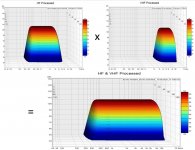
Mark Johnson Pass M2X amplifier, where there are modular input stages named after cities of their origin (Mountain View, Tucson, Austin, Ishikawa, etc). As this input stage would be using Hugh Dean's Aksa-Lender topology, it seemed natural to name it The Melbourne. My goal was to make a modular self-contained input stage for folks who have the M2X amplifier to be able to try out this topology. The Aksa Lender preamp was a single rail design (+48vdc), but to use on the M2X required a dual rail (+/-24vdc) supply. So I redesigned it on LTSpice to be dual rail, and in the process, made a few modifications for improved performance, plus the ability to use the M2X's native power supplies (which, may not be the usual ultra-low ripple supplies that I normally specify for a SE Class A amp, and assuming it comes from a typical linear trafo with a CRC with circa tens of mV of ripple. As I was refining the design on LTSpice, Paul Bysouth gave a suggestion to use a mu-follower on the output. A mu-follower takes for example, the 39R source resistor from the CCS device (DN2540) and splits it in a 1:2 ratio with 12R:27R resistors and placing the output node in between the two resistors and the CCS gate feedback after the bottom resistor. This proved to be quite effective at reducing the THD by about 4x - a significant improvement. This allowed the pre-amp stage to easily drive 600ohm load requirement that is the Edcor auto-former load on the M2X. In doing this, I played around with putting lower impedance loads on the pre-amp. For fun, I connected my DT880-250's to the output and listened. First thing to notice was an absolutely quiet background, no hiss or hum even with volume up but source off. When I applied music source, I was shocked how good it sounded. Natural, dynamic, clean and no fatigue. I expected high distortion since the 250ohm load presented was much higher than the simulated 600ohm design load. The bias current is running at only 45mA and voltage rails for the flat wooden board mockup was only +/15.5v provided through a Mark Johnson designed BJT cap multiplier (layout by Prasi), and power from an Antek 25w 15v toroidal transformer (what I had on hand).

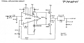
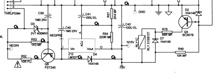
Here is the schematic on LTspice (ignore the series resistor on PSU rails - will be replaced with CRCRC):
717453d1542995688-diyaudio-watt-m2x-aksa-lender-m2xdb-melbourne-schematic-mu-follower-v1-3-png


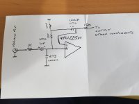
Here is the schematic after JPS64 laid it out:
719786d1543880473-diyaudio-watt-m2x-melbourne-th-v1-schematic-jpg


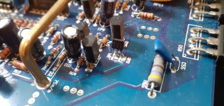
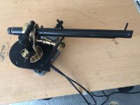
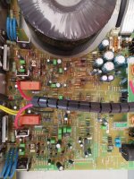
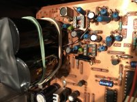
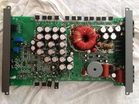
Here is a photo of the finished Melbourne module:
720059d1544004769-diyaudio-watt-m2x-mb-th-verify-build-02-jpg


Note that there is also an SMT based layout with TH caps, although I have not built and verified that version yet:
717426d1542988871-aksa-lender-pass-hybrid-m2-alph-m2-amp-mel-smd-pba-bot-v2-png


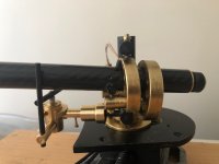
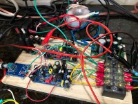
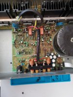
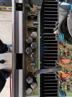
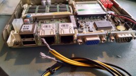
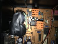
Here is a photo of the module in the mockup amp with cap multiplier, input and output RCA's and volume pot (10kohm Alps RK09 series). Careful attention to star grounding (note green wires) with star hub located at the (10R/diode bridge/100nF) ground loop breaker connected to earth ground:
720432d1544167446-jumas-easy-peasy-capacitance-multiplier-mb-th-verify-build-04-standalone-pre-jpg


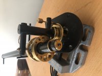
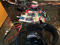
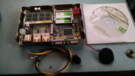
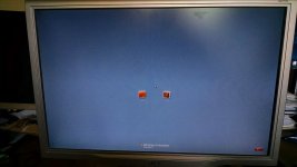
Here is a photo of the setup getting a first listen with headphones:
720693d1544279377-melbourne-class-headphone-amp-pre-amp-melbourne-standalone-preamp-hpa-02-jpg


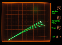
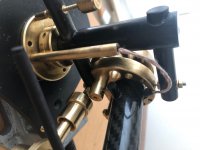
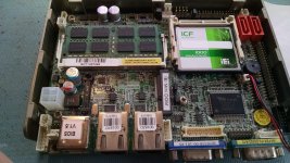
Here is a photo of the testing setup with alligator clips attached to the RCA jack outs for the headphone outputs:
720692d1544279377-melbourne-class-headphone-amp-pre-amp-melbourne-standalone-preamp-hpa-closeup-04-jpg


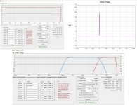
Here are some initial measurements 2Vpp into 2k2 ohm load:
720694d1544279377-melbourne-class-headphone-amp-pre-amp-melbourne-th-2vpp-2k2-45ma-fft-01-png


4Vpp into 2k2 ohm load:
720695d1544279377-melbourne-class-headphone-amp-pre-amp-melbourne-th-4vpp-2k2-45ma-fft-02-png


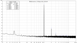
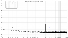
2Vpp into 240R load (representative of DT880-250's):
720696d1544279377-melbourne-class-headphone-amp-pre-amp-melbourne-th-2vpp-240r-45ma-fft-05-png


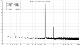
4Vpp into 240R load:
720697d1544279377-melbourne-class-headphone-amp-pre-amp-melbourne-th-4vpp-240r-45ma-fft-06-png


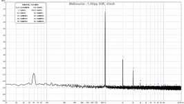
And even with only 45mA bias current, if one plays at reasonable volumes into 50R load, this is what you get for 1Vpp:
720698d1544279377-melbourne-class-headphone-amp-pre-amp-melbourne-th-1vpp-50r-45ma-fft-08-png


And here is a more typical normal listening level for 1Vpp into 50R load:
720699d1544279377-melbourne-class-headphone-amp-pre-amp-melbourne-th-2vpp-50r-45ma-fft-07-png


As you can see, the harmonic profile is always classic SE Class A with 2nd order dominant harmonic and decreasing 3rd order and higher harmonics. With a ratio of -17dB for H3/H2, the sound is very euphonic and the right balance of sweetness and articulation, and the absence of higher orders makes it non-fatiguing to listen to.

I would like to acknowledge the help and inspiration of fellow DIY'ers AKSA, JPS64, Mark Johnson, Prasi, and Paul Bysouth for this design. Without your help, passion, and energy, this would not be possible. Thank you!

Update Aug 6, 2019: yourownbuzz made a nice headphone amp with Thai:
772524d1564896110-melbourne-class-headphone-amp-pre-amp-top-jpg

Attachments

  • Melbourne-Standalone-Preamp-HPA-Closeup-04.jpg
    Melbourne-Standalone-Preamp-HPA-Closeup-04.jpg
    531.2 KB · Views: 3,581
  • Melbourne-Standalone-Preamp-HPA-02.jpg
    Melbourne-Standalone-Preamp-HPA-02.jpg
    555.1 KB · Views: 7,022
  • MELBOURNE-TH-2Vpp-2k2-45mA-FFT-01.png
    MELBOURNE-TH-2Vpp-2k2-45mA-FFT-01.png
    75.7 KB · Views: 3,522
  • MELBOURNE-TH-4Vpp-2k2-45mA-FFT-02.png
    MELBOURNE-TH-4Vpp-2k2-45mA-FFT-02.png
    77.1 KB · Views: 4,135
  • MELBOURNE-TH-2Vpp-240R-45mA-FFT-05.png
    MELBOURNE-TH-2Vpp-240R-45mA-FFT-05.png
    75.4 KB · Views: 5,218
  • MELBOURNE-TH-4Vpp-240R-45mA-FFT-06.png
    MELBOURNE-TH-4Vpp-240R-45mA-FFT-06.png
    79.1 KB · Views: 4,425
  • MELBOURNE-TH-1Vpp-50R-45mA-FFT-08.png
    MELBOURNE-TH-1Vpp-50R-45mA-FFT-08.png
    74.8 KB · Views: 4,130
  • MELBOURNE-TH-2Vpp-50R-45mA-FFT-07.png
    MELBOURNE-TH-2Vpp-50R-45mA-FFT-07.png
    76.1 KB · Views: 3,485

HELP - LM337 supply problem

Hi All,

I am having a problem fault-finding on the PSU in my Arcam Alpha CD 6.

The section is in the picture below.

The input to the LM337 is correct at 27v.

However, the output is only 1.5v.

I have changed the regulator but it is still the same.

The supply goes to the muting relay circuit and to the -ve supply for the opamps.


Any help fault-finding gratefully received.

Andy

Attachments

  • PSU.png
    PSU.png
    91.9 KB · Views: 212

Hafler 9505 & 9503 repair

Hi All
First time posting to this forum so forgive my timidity.

I have spent time repairing the Hafler 9505 and 9503 amplifiers and have collected a good deal of information on how they work and how to repair them. I can post schematics with voltages, an explanation of how to fix the thump problem as well as driver transistor burn outs.

Is there any interest in this information and if so, how and where should post it?

EngBen

Which is the best tube preamp for me?

Hello folks,

I´m looking for a stereo tube preamp to build. I know theres a lot of projects in the internet and here on this forum, but I´m newbie on this and need some help to decide which one will be the best choice for me.

I gonna use this for audio recording. Will feed it with line signal, and go back to an AD converter to record the audio with the tube color.

What I need:

*Balanced inputs and outputs (it´s not a must, but would be great to have it)
*stereo preamp
*I need something with a full range response... 20hz to 20k
*I want a tube warmth but I need it to be as clean as possible. (Lowest possible noise)
*I´m looking for fat low end and smooth highs sound
*I like the sound of ECC88s. A project with these would be great, but also open for suggestions.
*I´m and experienced audio engineer but newbie on electronics. Better if there´s a kit avaible or some instructions to build.

Hope you guys can help me

Thank u so much!

Help needed with Capacitors

I have a Myriad MA240 power amplifier i would like to replace and upgrade the main capacitors inside. However, the capacitors are 22mm wide and there is no room for a wider capacitor which appears to severely limit the choice i have for replacements. The capacitors that are inside currently are Nichicon LS 63V 4700uF . Can anyone recommend a significantly better capacitor to replace the 7 inside? Assume for now that money is no object and size is the main restriction. What do you suggest that has better specifications?

I am also looking for some suggestions on other upgrades for this amplifier as ive noticed there are some poor quality components inside that could be easily replaced such as the Potentiometer switches (1 already crumbled when i tried gently adjusting the bias). Who makes the best quality 5mm 500R potentiometers for the bias?

Here are some pictures of the board.

Attachments

  • signal-attachment-2020-02-20-195406.jpg
    signal-attachment-2020-02-20-195406.jpg
    579.9 KB · Views: 190
  • signal-attachment-2020-02-20-195446.jpg
    signal-attachment-2020-02-20-195446.jpg
    709 KB · Views: 192
  • signal-attachment-2020-02-20-195513_001.jpg
    signal-attachment-2020-02-20-195513_001.jpg
    550.3 KB · Views: 182

Best speakers/enclosure design for wall mounting

So the idea is to have shallow full-range speakers for wall mounting near a TV set. Speakers will be used for both music and movies though music quality is a priority. The only limitation in size is depth: up to 12cm, width and height are not limited.

Possible speakers that looks good from reviews:
Tang Band W5-1611SAF
Mark Audio Alpair 7
Fountek FR135EX

Any suggestions are welcome, cheers 🙂

IEI wafer 5252 single board computer Pentium atom Daphile

IEI single board computer 3.5" form factor Pentium atom 1.8gz. 12V power connector, driver disk. I think this has 2 gig of RAM..I need to check....


I'll post more pictures later today, but I'm also including a meanwell 12V power supply and a 2.5" sata cable connector. The unit is set up with Daphile loaded on the compact flash card with an IP address of 192.168.11.40. Just get it on your network and plug in a 2.5" drive and you are ready to go.


I will also include the factory IEI CF card that has a functional copy of Windows 7 embedded on it.


$90 shipped to USA addresses.

Attachments

  • iei wafer d5252.jpg
    iei wafer d5252.jpg
    722 KB · Views: 111
  • iei wafer 2.jpg
    iei wafer 2.jpg
    656.3 KB · Views: 113
  • iei wafer 3.jpg
    iei wafer 3.jpg
    577.6 KB · Views: 108
  • iei wafer 4.jpg
    iei wafer 4.jpg
    539.8 KB · Views: 108
  • iei wafer 5.jpg
    iei wafer 5.jpg
    664.3 KB · Views: 108

Wanted. Someone to redesign a vas stage of a amp

im looking for someone that would he willing to redesign a vas stage of a amp to use tubes instead of the bjt that it currently uses. Pay of course. If you interested please let me know. Im sure it might be silly but i have quite a few of these mosfet monoblocks and im currently using a 6922 tube preamp on the unity gain ouputs and i really like the sound. Seams like ot would sound better have a tubes go directly into the mosfet output stage vs through bjt's then onwards. Thanks.

ADS Driver replaements

I searched and found nothing so now I'm asking for help. The woofers in my revered A/D/S L200 speakers have died. One about 4 months ago and the other last week. I took them apart, disconnected them from the x-over nets and they are measuring shorted. Near zero R across the terminals.

So, does anyone know:

what a good replacement would be
or
where a real OEM replacement can be found
or
what the T/S parameters are for the original woofer

Many thanks in advance for any help that can be offered.

77 Cadillac Eldorado Radio exchange

Hi ,

besides fixing amps I have another little job where I can spend my spare time on. That´s our 77 Eldorado. As you can imagine the cars are pretty rare over here. For interest and pics see

my Eldorado site

I´m almost done with the engine compartment and starting to get stuff together for the outside and the interior. I once saw a modern radio with CD changer control that would directly bolt into the stock radio place. Also the knobs could be used. Problem is, I cant remember what the brand was or where to get it. Any idea where to find info?

I found a digital tape radio off a 1980 Eldorado on ebay, I think that would also fit into our car, but that radio doesn´t have any RCA outputs and i would have to use a Discman-to-tape adapter thingy ....

Sound Stream SA245 repair help

Hey guys, I'm working on an SA245 five channel amp. The amplifier blew some of the outputs and a MPSA14 driver along with a 10 Ohm resistor that connects the ground of the audio section to the PS ground. I've removed most of the outputs, along with the driver boards for them. One of the outputs turned a section of the PCB to charcoal.

In the power supply there are a couple of 75 ohm resistors that tie the gates of the switching MOSFETs to ground that have been discolored from heat. The SG3524 is switching the MOSFETs at around 57.5 kHz. According to the datasheet and with Rt = 1.91 k and Ct = 4.7 n the IC should be running at around 145 kHz. Could the IC be bad? What else should I be looking for? I've included some pics of the amp in the link below. Thanks 😎


http://picasaweb.google.com/grjr2000/Sa245#

Burson Audio V6 Classic opamps review

Hello, fellow diy and music loving friends!
I'd like to share with you my experience with Burson Audio V6 Classic opamps that were offered as free samples by mr. Carlos here on DiyAudio forum.
If this is a wrong location for this kind of post, moderator please move it to where it is appropriate.

I confess I'm a member of the TDA1541A "cult" and I believe that CD red book has enough information to sound really really good if the I2S signal and power supplies are done right. So what I like to do is get an old Marantz or Philips CD player and mod it using the information found mostly on this forum and also elsewhere on the web.

The newest project that I haven't made inoperable yet (fingers crossed) is a Marantz CD-273. It's a cheap nothing special player which originally sounds just ok. It had the LM833N opamps. I put the Bursons in but wasn't impressed much. It sounded better, but it was still somehow restrained and uninteresting to listen to. So I decided to mod it a little and bypassed everything behind the opamps so that the signal goes straight to good audio output caps and rca connectors. This unveiled the music quite a bit. Then i removed the SAA7220 oversampling and filtering chip and installed a reclock thingy that realigns the I2S signal before entering the TDA1541A. This mod also removed signal oversampling and cleared the 5V psu line of one noisy chip. Now the CD player sounds so much better it's barely recognizable and is actually a pleasure to listen to. Now it's a good enough platform for testing opamps.

The CD player originally uses one double opamp per channel where the left side of the opamp amplifies the signal and the right side buffers it. I used double and also single opamps with singles to double adapters.

I tried:
- NE5534N from Philips
- NE5534N from Signetics
- LME49720HA
- LME49710HA
- OPA637BP
- AD797AN

The Philips NE5534N were the most natural sounding with good dynamics and detail. Quite enjoyable really.
Signetics had deeper bass, but were
somehow muffled.
LME497x0HA were a tad more detailed, but a bit lacking in the midrange which made them too clinical.
OPA637BP distorted probably because of too low gain setting.
AD797 was soundwise somewhere inbetween the both NE5534Ns.

And then came the Bursons.
Since they are singles I put them in with Philips as buffers and the combo sounded better than an all Philips combo right away!
Great, then I tried them with every other opamp as buffer and the best buffer were the AD797s. The sound was natural, detailed, dynamic with deep enough well defined bass. The vocals were just amazing and level of dynamics which gives the music its emotions was comparable to a tube amplifier.
It's clear as day that these opamps are the best I have ever heard and they sound better than I thought opamps ever could.

Now I'm curious how much further I can push this CD player, as it seems the better it is, the more Bursons shine.
I'll replace the clock with a TentLabs one and sort out power supplies a little and then post my findings in this thread.

At the end I'd like to thank mr. Carlos for the wonderful opportunity to try the Burson V6 Classic opamps.
Thank you!

Attachments

  • 08F0A3AC-F09B-445F-BA39-F129BFD846FA.jpeg
    08F0A3AC-F09B-445F-BA39-F129BFD846FA.jpeg
    302.8 KB · Views: 405
  • 17128005-0F66-4EE0-90F7-85CBE833851F.jpeg
    17128005-0F66-4EE0-90F7-85CBE833851F.jpeg
    148.8 KB · Views: 402
  • E4AA3250-1448-4903-98B4-5CF34F1DF594.jpeg
    E4AA3250-1448-4903-98B4-5CF34F1DF594.jpeg
    230 KB · Views: 395

Please school me in input impedance / buffers/ sensitivity.

Sorry guys I have done tons of reading on here and a good few searches but I could do with a laymens introduction to the above topic.

I am getting keen to do an amp build over and above a small eBay board hanging off the back of my speakers!

I see a lot mentioned on this subject but I dont really understand it. We can all go to the hi fi store and buy 'separates ' and never hear this mentioned. So why does it become an issue the deeper we delve?

If anyone has a link to a good resource for absolute beginners on this subject would be great

Kind regards

Beefing up an NVA AP10P Amp

I have an old AP10P in a third system. I bought it back in the 90's so it has little intrinsic value. The AP10P is rated at 15W and I never expected it to rattle the walls, however I was musing the other day about "upgrading" it with a bigger power supply to give it a bit more grunt.

Currently it has an 18-0-18/30VA transformer feeding a 6A bridge rectifier and then 2 x 4700uF/35V caps to give +/- 25V rails. Output devices are BDV64A/65A using the 2mm aluminium floor panel (250mm x 200mm) as a heat sink.

As far as I can determine, the AP30 (30W) has the same output devices but a bigger power supply, namely a 25-0-25/100VA toroid and 4700uF/63V caps. So my thoughts are to replace the transformer, drop in a beefier bridge rectifier (25A) and replace the caps. A quick fiddle in Visio shows I can do this in its' current casework by rotating one of the amp boards.

I'd also need to change a few electrolytics rated at 25V on the amp boards and maybe tweak the "power" LED ballast resistor. Am I being too simplistic in thinking this is all it takes, or is there more to consider? Would I be changing the gain of the amp and therefore need to think about the value of the feedback resistor (3K83 on the AP10P, 18K on a bigger AP70, can't find a value for the AP30).

Thanks,

Duncan

DISSIPANTE 3U Drilling and tapping into radiator

hello friends, foes, lovers;

I've come across the conundrum that I do not know how in the world I would drill and tap my own holes, never mind where I would source the appropriate screws to mount my amplifier modules to the radiators in a dissipante 3U (or any other amp chassis for that matter)


-Thanks all in advance,
Andrew B

PS for anyone saying "check the archives" or "theres thread for that already"... booo0000o I looked my best, I'm not used to these forums and uh-oh-boy I cant find an efficient way to search for this topic <3 please understand <3

JX500/1D Protect mode

Hi
I am looking for help with repair of Jx500.1d of jl audio.
The first problem that was detected is contact with water and two pieces of capacitor 63v 3300uf exploited. One of the capacitors was in total short circuit.
Replace the two 63v 3300uf capacitors.
Now just turn on the LED that indicates protection.

These are some measurements that I made
TL494 IC2
IC2
1-0.998
2- 3.56
3- 4.69
4- 4.01
5- 1.438
6- 3.54
7- 0.01
8- 4.94
9- 0.01
10- 0.01
11- 4.94
12- 13.54
13- 4.94
14- 4.94
15- 4.94
16- 7.19

IC3 MP18021
IC2
1- 13.63
2- 13.63
3- 0.01
4- 0.01
5- 0.01
6- 0.01
7- 0.01
8- 0.05

IC 1 LM358
IC2
1- 0.01
2- 3.38
3- 2.460
4- 0.01
5- 2.797
6- 0.332
7- 7.84
8- 9.01

are my speakers too "far field" ??

Hey guys, I built the Swans 3.1 DIY speakers for my computer. They're fed through a Marantz sr585 receiver.

They sound great far away but I think they don't really come together for me since I am sitting so close to them. Would I be better off with a smaller speaker? coaxial speaker? I'm looking for something pretty hifi 🙂 budget is somewhere between $300-500


Thanks!

Edit: I have a sub

Attachments

  • 20200219_161017.jpg
    20200219_161017.jpg
    609.7 KB · Views: 330

ICEPOWER Monoblocks

Custom Monoblock Amplifiers 200W

For sale 2 custom monoblocks made by myself. They are based on the IcePower 200ASC modules (200w with integrated power supply). Chassis is one piece aluminum with a walnut front face. It has LEDs that indicate when on and is powered by the front switch. The connectors in the back are single ended and balanced (Neutrik). Very compact 9.4 x 5 x 2 inches. Asking $300 for both.

Thank you,

IMG-9199.jpg


IMG-9200.jpg


IMG-9201.jpg


IMG-9209.jpg

Parasound HCA-1500 component upgrades

I have a HCA-1500 with bad left channel ... shorted output drivers ... so it's time to go ahead and do a recap at the same time. I'm having a shop do it, but wondering if there are commonly accepted devices that are worth considering an upgrade.

The power supply specs on the Parasound site are 60,000uF (Nichicon), but my unit must be later in the production line, as it has a higher rating of 80,000uF (Elna).

I notice that Wima film caps seem popular, sometimes in place of electrolytics, so I'm wondering how this decision is typically made.

Yes, I'm having a shop work on, but I know John pops up here on occasion, and if he, or anyone else, can recommend even a few smart updates, I would appreciate it.

Part of why I am keeping this amp and having it worked on is that it is a fantastic value. It's affordable audio muscle that sounds great in my system and there is no way I can replace with anything that will sound better.

Thanks John!!

Engl Fireball E625 noisy

I have an Engl Fireball E625 that has just had the filter caps and tubes replaced, and following the schematic biasing technique I'm getting 2.3 and 2.5vDC on those testing points. Valves are all behaving themselves even though there seems to be more blue hue than usual. I have read in many forums that the problem I'm getting is quite common in these amps however no one has found a solution. When the ultra channel is used it is noisy hum and seems to be microphonic, I am using EH12ax7's and I have tried swapping them out with others but the problem is always the same.
I have taken some voltage readings as follows:
V1 pins 1 & 6 = 97vDC & 84vDC
V2 pins 1 & 6 = 217vDC & 162vDC
V3 pins 1 & 6 = 245vDC & 223vDC
V4 pins 1 & 6 = 252vDC & 261vDC

and for the power tubes I'm getting -41vDC for 415 and 422vDC on each tube.
readings were taken with volumes all turned down. Readings do not change after switching channels.

thanks for any help at all

J.

Levinson 332 lifeless, need some help to get this powered up

Hi all,

I have had this amp 10 years now, it's been sitting in storage until I had time to change out the caps and do all the ECO's, which are now done, but the damn thing won't start now and I am working my way thru the schematics and just can't figure out why. Yes it was working 10 years ago when parked.

There may be a startup sequence I am not familiar with, so it could be just me, but I have read the manual and I am just not getting any LED light up on the front panel, nor LED100 or LED101 on the VSMB board. I have confirmed I'm getting power to VSMB board and VR1 and VR12 are working, there are voltages all around the board, but when I push the main power button on the front, nothing, no change, no current draw...nothing. Is there some sort of time delay? Manual says nothing about holding in the power button to turn on, only off.

Any thoughts?

Would appreciate some help from someone who knows the 300 series please and thanks.

Cheers

Stellavox amplification help please

Georges Quellet developed the Stellavox line of tape recorders 70 years ago. in the early 1970's he introduced his SP series which lasted for 20 years until the company went defunct in early 1990. That series used the same potted/plug-in amplification module originally designated SPA-SOA for most of the the whole time period. The later modules were un-potted and designated as SPC-SOC. The same circuit was used in their acclaimed TD-9.View attachment img20200215_09044655.pdf

The schematic of the module appears below. The "P" refers to the two transistor preamp and the "O" refers to the four transistor output amp. Four of these were used in each tape recorder; two per channel; two per each playback and record function.

I'm looking for any suggestions for updates to the circuits - not total rebuilds. A few folks have contacted me with improvement suggestions including adding constant -current diodes but I never followed up on them. Your input is appreciated - and thank you.

Charles

The real reason to offset the tweeter on baffle?

Notice the "question mark" since I have not run all the simulations, but it's a matter of intuition. Some speakers have the tweeter offset on the baffle to minimize baffle diffraction at least that is what most people think it would be.

But the other reason that is not usually spoken off is if the tweeter is offset, and the woofer is at the center, their diffraction signature is different at different frequency.

For example, if both tweeter and woofer are at right at center, then they will happen to have a dip and peak at the same frequencies (or approximately) which can be pretty bad. For example, on a 8in. width baffle, the diffraction dips at about 4K - 5KHz, but they would both dip at the same frequencies so it could be pretty bad potentially.

But if the tweeter is offset, then the tweeter and woofer will dip at a slightly different frequencies so you sort of spread out the diffraction so it won't be as bad.

If you use shallow xover slope, it is more serious. But if you are using steep slope xover, then it is not quite as serious. For example, if you cross at 3KHz but using shallow slope, then on the tweeter or the woofer will be more seriously affected by diffraction. But if you're using steep slope, then it's either or but not both, or if you lucky, the steep slope may filter out the drivers before diffraction set in.

Attachments

  • tweeter_offset.png
    tweeter_offset.png
    3.4 KB · Views: 468
Projects by fanatics, for fanatics
Get answers and advice for everyone wanting to learn the art of audio.
Join the Community
507,558
Members
7,876,951
Messages

Filter

Forum Statistics

Threads
405,719
Messages
7,876,951
Members
507,558
Latest member
reeya