Dear all,
for the last couple of years i have read and found a lot of interesting topics about horns, hifi, amps and other interessting stuff about my hobby (and small business by now next to my full time job as an optics engineer) on this website. Finally i decided to join your community as well and i am very excited to learn and share!
Sadly i directly have to come up with a question on the Hiraga 30W Amplifier...
Short background on the history:
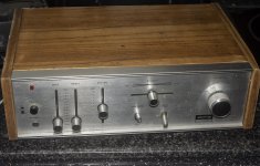
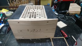
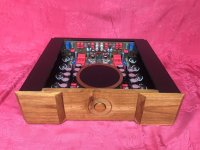
I am running two of those beatiful amps already, which i have build years ago with an friend of mine, who has passed away too early sadly. Now i wanted to give it another try on my own, because i am really fascinated by the sound of these amps and i wanted to learn more about electronics and i have better capabilities to manufacture nice enclosures.
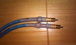
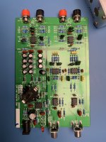
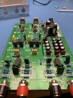
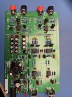
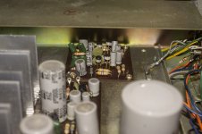
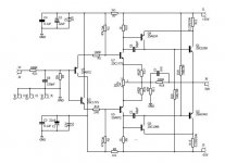
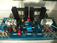
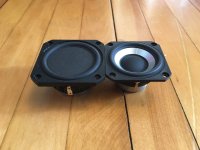
I found the PCB's on Ebay three years ago, a week ago i decided i wanted to finalize the amps already.... It's the blue ones with the little monster printed on them (no link anymore, but see pic's attached). Meanwhile i have found out, that they are very similar (but not identical) to those ones available here:
Hiraga 30W A class Amplifier - HiFiStor
But they are not completly similar, because
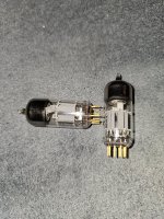
- the driver transistors 2SA634 and 2SC1096 are different in my kit.
The power supply came with transistors instead of diodes.
The output transistors were off as well (2SC5198 and 2SA1941 instead of 5200 and 1943)
All in all, looking back, i am afraid the ebay kit was a wierd mix of transistors and PCB's and a knock off....
The Problem:
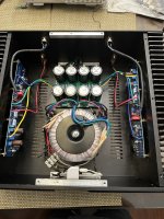
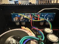
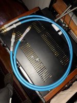
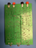
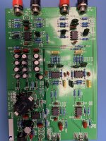
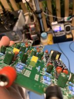
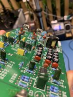
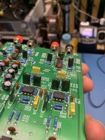
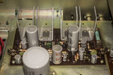
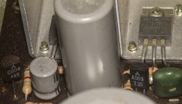
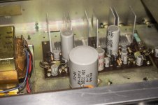
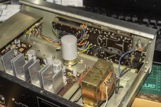
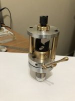
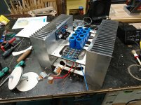
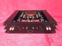
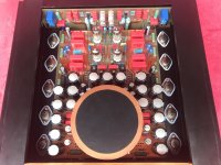
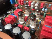
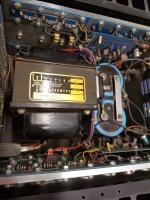
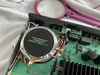
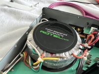
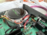
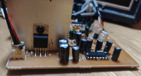
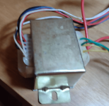
I have checked the circuit and values of resistors several times. Both channels behave similarly. My Power Supply runs at +-34V with lots of capacitors (see picture), so that should work fine.
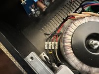
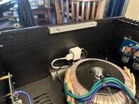
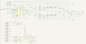
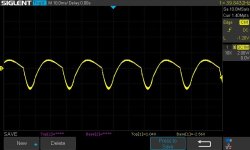
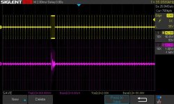
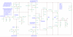
I nevertheless only measure a very small voltage across the 0.33R resistor with 47k Resistors as R3 and R2 in place (from schematic in the link above). Putting a 200k Stereopoti in parallel allows me to increase the Voltage drop across R12/R13 (its the 0.33R ones) to around 0.2V to 0.25V (quasi cold state). Slowly lowering the resistance further, all of the sudden i can hear a "plop" and one of the two power transistors shorts and is broken (i think by then i am around 33k in total). They are attached to rather large Fischer Heatsinks (see pictures). The 300R resistor R18 looks a little brownish by now.
I have checked the 0.6mV across Q4 & Q3 and that looks fine. There is supposed to be a Voltage at R10 & R9 of around 1V (1mA@1k from the original Hiraga schematic), which seems to be a little low at my setup with around 0.65V. The zener-diodes show 22.0V, as supposed to be.
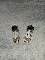
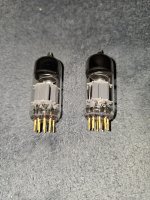
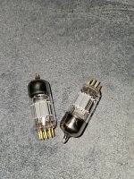
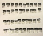
I am thinking that my transistors 2SA940 and 2SC2073 do not fit well as the drivers. The datasheets are hard to compare (for me and my limited knowledge/experience) because the data given does not match (Voltages and currents where the Data is given varies, see attached pdfs).
So my question now is:
Can anyone help me to find out what goes wrong here?
Is it worth changing the drivers to the 634/1096 ones?
Might it be a problem of matching the input transistors?
Waht am i overlooking, because the problem occurs in both channels?
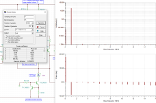
How can i systematically track the error (i do not know which voltages should be where without simulation the circuit?)
I am a little lost beacuse i am in the wierd state of generally understanding how a transistor works, but still beeing (massively
😉 ) overwhelmed with analyzing schematics to great detail. And then there are three versions of this amp (my old one, the ebay one which is the problem, the linked one) with different transistors and resistorvalues, which dont make it easier to truly understand the important parts of the circuit.
Sorry for the long story and thanks a lot for your support!
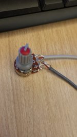
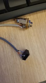
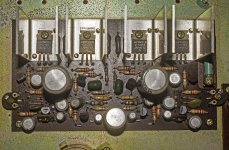
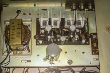
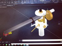
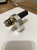
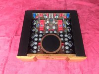
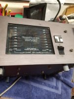
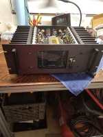
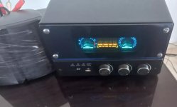
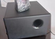
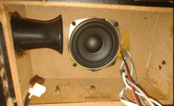
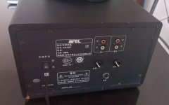
For a better understanding i have attached a few pictures of the amplifer.