Hi all,
I had this idea on my mind to design amplifier that will have 2SK170 (or LSK170 or LS844 matched pair) used as LTP producing respectable THD performance while delivering nice sound.
For output stage I wanted to use IRF9240 and IRF240 MOSFETs.
Theoretically it should work.
But it does not want to for some reason.
I simulated LTP and VAS stages separately and they worked fine.
Adding bias transistor servo and output stage broke it for some reason. Maybe I need to tweak the bias?
Anyway, will be thankful for any help.
Attached is TINA-TI simulation file.
Attachments

Last edited:

Regarding Vbe multiplayer circuit:
If I understand correctly, we need to have voltage drop equal or more the turn on voltage of the Mosfet which is IRFP240 and looking at the data sheet https://www.vishay.com/docs/91210/irfp240.pdf
Gate to source threshold voltage min is 2V max is 4V.
To double check, Vbe for BD139
https://www.mouser.com/datasheet/2/389/bd135-1848980.pdf
is 1V
Given that information can we conclude that we need 2x to say 5x of multiplication???
Formula is Vx = Vbe * (1+R1/R2) where R1 base collector resistor.
If r1 is 2k and r2 is 330R + 1k adjustable we get 2/0.33 = 6 and 2/1.33=1.5
So Vx will be in the range of 1.5 to 6
Last edited:
You have the IRF240 and IRF9240 opposite of where they should be.
Attachments
Should be fun to play around with.
You loose another 3 to 5 volts of the rail with mosfet.
No benefit really with CFP More of a stability issue than
anything else.
Easier, more power , more stability with BJT Darlington
output.
Single pair of outputs is fine for this power level.
But with 2 pairs, distortion lower and will drive 4 ohm loads
very nicely
So no real benefit of using MOSFETs in output stage?You loose another 3 to 5 volts of the rail with mosfet.
No benefit really with CFP More of a stability issue than
anything else.
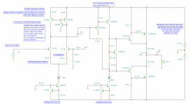
Wanting 100W of output power changes everything. Reflected in the attached schematics. Pretty much all transistors are now changed.
Not working still ugh
Looks like emitter follower driver transistors KSA1381 and KSC5305 are to blame.
Compressed is sim file with transistor macros for convenience.
Idea is taken from application note for LS844 https://www.cordellaudio.com/book/datasheets/LS844.pdf
and DH-220C amplifier https://www.cordellaudio.com/poweramp/DH-220C_MOSFET.shtml
Attachments

Last edited:
You've changed to EF so everything is upside down again 😉, also your emitter followers are not connected as emitter followers!
Mosfets easier to drive so drivers can be low wattageSo no real benefit of using MOSFETs in output stage?
very low current to drive.
Voltage threshold much higher to turn on 3/4 volts
So you loose more peak swing to rail voltage.
For low distortion at high frequency need high bias current.
100ma per device
Thermal tracking similar to BJT but Bjt will over track bias.
So few tricks and numerous circuits to make BJT VBE multiplier
track correctly.
lots of fun.
BJT need higher current to drive but turn on voltage very low .7 volts
So drivers usually larger. but swing to rail higher.
Thermal tracking easier since both BJT same thermal behavior
idle current lower 30ma per device.
Fet input for low noise
If you want amplifier with higher distortion or dominant 2nd harmonic
profile. Amplifier can be simplified to have more distortion.
Second gain stage or VAS is basic class A gain stage. So using
more simple topology or simple single transistor VAS with higher current
driver. 2nd harmonic behave like typical higher distortion class A
So likely benefit of mosfet also with simple amp.
Since current so low to drive. No drivers
Vas drives them directly.
For low distortion usually not used.
But To make Vas have more 2nd harmonic.
Beneficial for that aspect
Because even more load placed on Class A Vas stage.
Driving mosfet directly
For more fun use old school bootstrap current source.
Works fine, fun makes people whine LOL
I was gonna do simplified, but tossed all the stuff in there.
VBE might over track, can do something else , or plenty MI amps
just dangle it near the heatsink not attached. seen it done with TO-92
as well and same thing mounted near heatsink.

VBE might over track, can do something else , or plenty MI amps
just dangle it near the heatsink not attached. seen it done with TO-92
as well and same thing mounted near heatsink.
Attachments
Last edited:
So likely benefit of mosfet also with simple amp.
Since current so low to drive. No drivers
Vas drives them directly.
For low distortion usually not used.
But To make Vas have more 2nd harmonic.
Beneficial for that aspect
Because even more load placed on Class A Vas stage.
Driving mosfet directly
For more fun use old school bootstrap current source.
Works fine, fun makes people whine LOL
So the idea is to beef up LTP input stage to remove all distortion as well as output stage; and use VAS to sort of inject 2nd order harmonics?
By the way, running it into clipping gives about 30V into 4ohms before it clips. Does that mean 30/1.41 *30/1.41 /4 = 110W of power into 4 ohm?
If bootstrap swapped to current mirror - will that pretty much kill 2nd order harmonics? I simulated it and THD goes from 0.07 down to 0.02...
Already did first thing when I saw the post. Played with few things, added CCS to VAS , played with gain, simulated distortion, in other words had some fun lolzip with Tina file attached if you didnt notice p#16
Should open and run
- Home
- Amplifiers
- Solid State
- Discrete amplifier using 2SK170 JFETs for LTP inputs and MOSFETs for output stage design and build