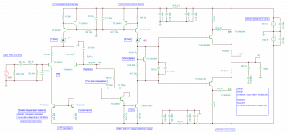
Should be close to 21 volt RMS
So pretty much 100 /110 watts.
for the most part, it is simple VAS
no beta enhancement, so little more load on the FET.
then yes VAS is also driving more load without power transistor drivers.
But Mosfet very easy to drive. So can be done with mosfet.
BJT it would be impossible to drive directly from Vas.
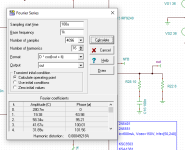
If you removed bootstrap current source
2nd harmonic would still be high. just slightly less.
But yes VAS is class A so you get 2nd harmonic.
and simple bootstrap current source will get little more.
lower THD would use the usual approach.
Beta enhancement and even cascode for VAS
That is common approach to remove 2nd harmonic distortion.
which is most of the % rating.
And then to reduce the load on the Vas then you use driver
transistors for outputs and THD drop further.
you would loose all the second
harmonic and have typical 3rd harmonic and odd ordered
harmonics phase would change.
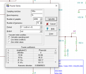
this amp
upper harmonics are about same level as .001% amplifier
but the strong 2nd makes the amp measure around .05%
and phase of uppers is different than typical solid state.
even if input Fet changed to BJT THD be about same.
Maybe .01 %
Fet might contribute a little because they cant drive loads as well.
So the higher load T6 1381 gives the Fets a little workout.
But 1381 has pretty good gain and easier to drive.
If it was a BD139 or MJE243 likely would get little more 2nd
harmonic
So pretty much 100 /110 watts.
for the most part, it is simple VAS
no beta enhancement, so little more load on the FET.
then yes VAS is also driving more load without power transistor drivers.
But Mosfet very easy to drive. So can be done with mosfet.
BJT it would be impossible to drive directly from Vas.
If you removed bootstrap current source
2nd harmonic would still be high. just slightly less.
But yes VAS is class A so you get 2nd harmonic.
and simple bootstrap current source will get little more.
lower THD would use the usual approach.
Beta enhancement and even cascode for VAS
That is common approach to remove 2nd harmonic distortion.
which is most of the % rating.
And then to reduce the load on the Vas then you use driver
transistors for outputs and THD drop further.
you would loose all the second
harmonic and have typical 3rd harmonic and odd ordered
harmonics phase would change.
this amp
upper harmonics are about same level as .001% amplifier
but the strong 2nd makes the amp measure around .05%
and phase of uppers is different than typical solid state.
even if input Fet changed to BJT THD be about same.
Maybe .01 %
Fet might contribute a little because they cant drive loads as well.
So the higher load T6 1381 gives the Fets a little workout.
But 1381 has pretty good gain and easier to drive.
If it was a BD139 or MJE243 likely would get little more 2nd
harmonic
Last edited:

I want to build this and give it a listen 🙌
After I build that voltage follower
And many others things in the queue lol
After I build that voltage follower
And many others things in the queue lol
Circuit design easy for me.
Board design I can do but very slow, lol.
So if you good at board design, projects move pretty quick.
BJT Quasi output also good way to get 2nd harmonic.
And also same trick. Use Simple Vas has high 2nd.
Can also do simple darlington transistor output.
Or big T03 metal can outputs, that nobody likes...oh well.
No need to overbias class A/B and call it something else.
it does nothing. well actually it does.
It makes the 3rd rise. 2nd all Vas
Last edited:
I am pretty good with KiCAD, sort of like video game for me, can spend hours doing that thing.
Also Phil’s lab YouTube channel has bunch of good tips for board layout and a course from that dude for mixed signals design board that I’m taking right now.
I can layout SMD or THT components. Recently got this hot plate thing from Amazon and “baked” few SMD boards. So much faster than through hole components assembly…
What about all this vertical vs lateral MOSFET for audio?
Just been reading on - https://sound-au.com/articles/hexfet.htm#s51
Maybe I should use these?
https://www.profusionplc.com/parts/ecw20n20
https://www.profusionplc.com/parts/ecw20p20
2SJ50/2SK135 and 2SK176/2SJ56 are nowhere to find apparently
Just been reading on - https://sound-au.com/articles/hexfet.htm#s51
Maybe I should use these?
https://www.profusionplc.com/parts/ecw20n20
https://www.profusionplc.com/parts/ecw20p20
2SJ50/2SK135 and 2SK176/2SJ56 are nowhere to find apparently
Last edited:
lateral I wont give a great opinion about.
dont care. hard to get outdated and extinct.
Ft are miles apart. pretty much find them annoying
real life and models . even models are limited
and poor.
Extremly high power amps with a lot of devices.
even worse. cant stand them and never got it.
dont care. hard to get outdated and extinct.
Ft are miles apart. pretty much find them annoying
real life and models . even models are limited
and poor.
Extremly high power amps with a lot of devices.
even worse. cant stand them and never got it.
- Home
- Amplifiers
- Solid State
- Discrete amplifier using 2SK170 JFETs for LTP inputs and MOSFETs for output stage design and build