B&C 18TBW100 4ohm speaker subwoofer

I'm thinking about reusing 4 of these speakers that I currently have in some Keystone subwoofers since I'm doing shows in smaller clubs where front loaded could be a better fit. could someone please tell me if these figures look right? not much of a port according to the subbox.pro designer.

https://subbox.pro/en/b/aPuzX0mJS

https://www.bcspeakers.com/en/products/lf-driver/18-0/4/18tbw100-4

Quick feedback on some tweeters

Hello all, I'd like to build a small monitor speaker for my bedroom with nearfield usage. I am flip flopping between two tweeters to use. I intend to use a waveguided tweeter as they simply sound much better to me, I have really grown tired of the typical dispersion mismatched 1" dome to most woofers. I intend to utilize these for mixing purposes, but also keep things within my budget (no satori stuff for instance).

My two tweeters of choice are the ND25FW and XT25/DX25+Wg300. My current main living room speakers utilize the ND25FW and I find them to be totally inoffensive tweeters that just do things right to my ears. I don't feel the need to apply corrective EQ to them and my mix translation is good. I seem to be able to work with them for hours without much in the way of fatigue and I feel they image well.

I also have in my possession a WG300 and DX25 + adapter. It appears as though the DX25 and this waveguide have a pretty rough dome reflection that causes a dip in the upper treble (I found this to be problematic) so I'd like to try the XT25. It does however look to have very narrow dispersion (referncing heismann data) but I'm not sure how much of a concern this would be.

Should I stick with what I know works well, or try for something different with the XT25+Wg300? My dumb consumer brain tells me the costlier option would offer better performance.

Rega Mira 1: Rising DC offset in right channel

Hi folks,

I’m currently trying to repair a Rega Mira 1 Clamshell with a DC offset problem. The issue is that DC offset in the right channel is quickly rising when turning up the volume. DC Offset at zero volume is around 10mV. From the 8 o’clock setting the DC offset in the right channel starts rising. At around the 9 o’clock setting the DC offset has risen to ~300mV and the protection circuit kicks in.

What I've checked so far:
  • Power supply seems fine. Power rails +/-15V, +/-40V measure ok with low ripple. Caps have been replaced.
  • Preamplifier output looks fine so it looks like a problem in the right power amp circuit.
  • When injecting a test signal, the sine waveform in both power amp channels looks fine at various volume levels (no clipping).
  • I’ve checked the power transistors and compared some voltage measurements on the left and right output circuits but haven’t been able to find any obvious faults.

Any tips on how to troubleshoot this issue?
Thanks you.

PS. Circuit diagram for Rega Mira 2000 (similar): Rega Mira 2000

Upgrading drivers of an existing old cabinet (pics)

Hi all,

I got this vintage Japanese speaker set sometime back, it's a 50w speaker and some drivers are blown/damaged. Now I'm thinking if I could upgrade it to a better speaker meaning I'll replace drivers and crossover but keep the same cabinet.

It's external dimensions are (made of 20mm plywood)
H 62cm
W 36cm
D 31cm.

Has a 10in woofer. Would be great if I could convert this to something like Scanspeak Discovery 3w classic. Is it a worthwhile project? I have attached some pics .
20230719_223429.jpg
20230719_223720.jpg
20230719_223815.jpg

20230719_223349.jpg

Audio Note amplifier Mystery

Hi Tube community at DIY Audio, I was hoping to get some help. I've been very fortunate to get hold of a pair of what I'm certain are a clone of Audio Note Kegon - Balanced for a steal... I'm confident that they're made by Alp Audio, who used to be Peak Audio, who distributed Audio Note in Hong Kong.

Unfortunately, it came with two out of five tubes. I know two of the tubes are 300b's and there is a gain stage with a 6j7G (which deviates from a AN Kegon but came with amp). The Kegon is a 10Y - Interstage - 300bPSE.

It appears to be a 6j7G - Cap Coupled - unknown tube (10Y?) - to 2x 300b's. The other tube I'm unsure of is the Rectifier. I would assume it's a 5U4G, as the other amp I got is and the majority of Audio Notes amps are too.

Anyone have an idea on where to start?

Pictures say a 1000 words:

1689884943074.png


1689884987136.png

Single high voltage cap vs 2 lower in series for split rail power supply?

I am currently working on making an aleph m amplifier and am working on the power supply. I have some caps that are rated at 63v and this value is much higher then what my rails are for the amp. It runs at plus minus 17 volts. I could be wrong but could I not just put a cap from the + 17 to the – 17 as it would only be seeing 34v and that would be much lower than the rated value and would give me more capacitance then if I put 2 of the 63v caps in series. I looked for a few hours yesterday and could not find an answer that made me feel assured.I am currently working on making an aleph m amplifier and am working on the power supply. I have some caps that are rated at 63v and this value is much higher then what my rails are for the amp. It runs at plus minus 17 volts. I could be wrong but could I not just put a cap from the + 17 to the – 17 as it would only be seeing 34v and that would be much lower than the rated value and would give me more capacitance then if I put 2 of the 63v caps in series. I looked for a few hours yesterday and could not find an answer that made me feel assured.

DIY DAC + Streamer suggestions?

I got a spare Raspberry Pi3+ and a 2.5" 500GB SSD, I am sick of the amount of cables and AC adapters not to mention my DAC which I can't stand any longer (a Beresforf Caiman SEG), I'd like to put together in a single box both a streamer and a DAC as to get rid of my Caiman SEG and the MacMini which even tho does well takes space and extra cables.

The DAC would need one-two optical inputs (one for the TV and eventually another one for the CD player even tho it's built in DAC does sound very well), dunno if an R2R or a chip based one.

Should not be hard to build a PSU to power both DAC and storage-streamer.

Do you have any suggestion to what to look at?

Grazie

JJ EL509s in Triode - specs ?

Saw that JJ sell an Octal version they label EL 509s. Never looked at this tube before. I know there are the original top-plate versions out there too.

I've seen it referred to as a Sweep Tube and these are often very nice when wired up in Triode mode. But JJ provides nothing about triode wired operation.

Anybody using this tube in triode mode ? (it's not a low cost tube, not sure who is buying it in enough volume to justify JJ to keep it in production ?)

https://www.jj-electronic.com/en/el509s

150W overload protected amplifier

My first 150W amplifier using TIP2955/3055 transistors with overload protection using op-amp.
This amplifier is motivated by the need to protect the whole system against inrush current when the input signal is high. In fact, these protected amplifiers are specifically required to do some modal analysis tests in vibration labs to drive shakers. We have come across high failure rate of amplifiers due to sudden application of input signals while the shaker is connected. Therefore, I designed this circuit to limit the current of the output stage using op-amps and few other components.
I also tested it with audio signals and speakers and it worked like a charm.
THD: 0.003%
Frequency response: 1 Hz to 37 kHz
Supply voltage: +/-24 to +/-30
Lifesaver components that eliminate HF oscillation even with no load/light load condition:
1. Feedforward resistor R24 (1k)
2. Bootstrap resistors R14 and R15 (1.5k)
3. Zobel RC on the output
4. Feedback capacitor C8 (100pF)
5. Also C5 and C2 have helped a bit more.

Note: You will need a good power supply and a big heat sink for the power transistors.
Rx is wire jumper or very small resistor say 1.2R

Attachments

  • amplifier120w.jpg
    amplifier120w.jpg
    248.6 KB · Views: 377

NE5534N best quality replacement?

I have a power amp that uses NE5534N op amps for the electronic balanced inputs, it is in a unity gain configuration. It looks as though these are dead and I would like to replace them with the best quality modern op amps having the same pin out. Can anyone tell me which would be the best new device in terms of sound quality? Since there are only two of them I am not too concerned about the price, quality of sound is most important.

DIY Amplifier and Preamplifier Chassis

Two very nice chassis for DIY projects. The Krell Amp Chassis is of course a knock off (Aliexpress) but is still very nice quality and great value. The silver Preamp (or small amp) chassis is super nice as well.

$250 CAD each or $400 CAD for both. Local pick up in Vancouver, BC only.

Cheers and all the best.

Attachments

  • IMG_6228.JPG
    IMG_6228.JPG
    550.2 KB · Views: 210
  • IMG_6227.JPG
    IMG_6227.JPG
    528.6 KB · Views: 216
  • IMG_6226.JPG
    IMG_6226.JPG
    568.4 KB · Views: 215
  • IMG_6234.JPG
    IMG_6234.JPG
    427.8 KB · Views: 228
  • IMG_6229.JPG
    IMG_6229.JPG
    510.7 KB · Views: 218
  • IMG_6230.JPG
    IMG_6230.JPG
    656.7 KB · Views: 220
  • IMG_6231.JPG
    IMG_6231.JPG
    365.2 KB · Views: 208
  • IMG_6232.JPG
    IMG_6232.JPG
    427.9 KB · Views: 214

High quality ADC

Hi
Looking for a high quality analog to digital converter with SPDIF output, have a Flex 8 that only has digital input and I'm trying to find a good performance ADC to connect the turntable to the minidsp.
Found two good suggestions here (ADDA24QS and nihtila.com ADCs) but both been out of stock for a while and don't seem to be in production anymore.
Thank you.

The Rhombus sub

This project is pretty straightforward except for the enclosure shape. It is a passive 4 cubic foot sealed enclosure loaded with a down firing Dayton Ultimax 15. Power is provided by a bridged Crown XLS1002. I've built many subs over the years and listened to far more and am very pleased with the Ultimax 15 for both music and home theater. My main speakers (Campbell/Holtz Bourdeaux kit) are capable of excellent bass themselves and after much tweaking I settled on a low pass to this sub of 50 hz with a 12 dB slope.

I originally settled on the shape as a joke to myself in that my carpentry skills are unable to produce anything with square joints 😛 At the same time I believed the shape would provide visual interest. The enclosure is of 3/4" MDF and sits on furniture legs sourced from Amazon and bolted to the recessed downward facing baffle.

I realized as I began construction that due to the shape of the enclosure and the viewing angle from the listening position it would appear visually smaller than it actually is. This illusion is due to the fact that the front face of the enclosure is not orthogonal to the line of sight from the listening position; it's receding plane fooling the eye.

Test fit of driver. Baffle will face the floor when installed with furniture legs bolting into the corners of the recessed baffle. Two horizontal window braces already installed and additional vertical bracing is being added between the baffle, window braces and top.
20200503_174059.jpg


Another interior view before all sides are attached. Short vertical braces installed at each of the woofer screw hole locations reinforce the baffle by spreading loads into the window braces and cabinet sides. Inside of cabinet top (bottom in this view) will have an X shaped brace installed for reinforcement.
20200503_174125.jpg


Initial "does it work" test. I ended up shortening the legs considerably as I found these too tall. Spring type binding posts can be seen as well.
20200510_171550.jpg


Enclosure is veneered with paper backed mahogany using contact cement; my preferred method.
20200524_172541.jpg


Experimented with a somewhat distressed finished on this project. I liked it.
20210307_170453.jpg


The forced perspective in photographs usually disguises how slanted the front and back sides really are. This view shows true shape to good effect.
20210307_170521.jpg


Final placement in the living room/theater/listening room.
20210307_170542.jpg

Free: NOS on-wall speaker cabinets

Back in 2005-2006 I developed an on-wall speaker for use with flat panel TVs which sounded good for its size and application. I have a bunch of extra cabinets for which I’d like to find homes.

Here’s a link:
http://www.dnaudio.com/DNA-Sonic-Decor-Model-100-On-Wall-Speakers.html

They’re made from 1/2” MDF with a horizontal brace between woofer and tweeter. The cabinets measure 15.75” H x 10” W x 4” D with 6L internal volume. Mounting holes were for the Vifa D27TG35 and Peerless 832873 but can accommodate any of their 5-1/4” HDS woofers.

Cabinets are in white and black textured paint. I had grilles made in white, light gray, and black.

The speakers are design to have a decorative trim panel attached using Velcro. I still have some in wood veneers and solid gloss black and white and can include until depleted.

They’re wall mounted using a Hangman bracket.

I’m offering the cabinets with 1 pair of grilles for free - you only need to pay $50/set for ground shipping anywhere in the lower continental US. Free local pickup at my storage unit in SoCal is also an option. No woofers or tweeters or crossover components are included, but are available for sale separately. I can also provide a copy of the crossover schematic if you want to build it as I originally designed

4EDCFD33-387D-41C9-861E-C8D3DC19DA44.jpeg 3FAEFACD-4E89-417A-A118-76BC7A7B8D33.jpeg 8EB2207A-F8F0-4A22-AF3F-005A0E325449.jpeg

Balanced preamp Input Level Sensitivity

Hi,
I need some advice, how to change gain in this balanced preamp board? Which resistors I should to change?
There is small description about this board:

The distortion and noise of this line is much lower than that of a normal circuit, so the circuit looks less complicated and slightly more complicated, and the purpose is low distortion and low noise. In general, to convert the balanced signal into an unbalanced (single-ended) output signal, you can use 1/2 NE5532 plus 4 10K resistors, which can be achieved by connecting IC2A in the figure. At this time, R5~R8 are taken as 10K, a pair of balanced signals are input from the left end of R5 and R6 respectively, and a single-ended output signal can be obtained from the right end of R9. This differential amplifier circuit is quite simple. The output noise is also low, which can reach -104dBu (0dBu=775mV), but still feels a lot of noise. For this reason, the so-called double balance stage is adopted, that is, two differential amplifier stages are composed of IC2A and IC2B, and the balance is received at the same time. The input signals are added together to partially cancel out the uncorrelated noise, resulting in a 3dB noise reduction and improved circuit common-mode rejection ratio (CMRR).

Further improvements are also added to the first stage voltage followers IC1A, IC1B before IC2A and IC2B. This not only improves the input impedance, but also reduces the resistance of the eight resistors R5, R6, R7, R8, R13, R14, R15, and R16 of IC2A and IC2B from the original 10K to 820 ohms, greatly reducing the thermal noise of the resistor. Finally, the noise of this stage is reduced by -112dBu, which is 8dB better than the traditional single-difference circuit above.

My amp Class D need at least input 200mV-6V 102db. At the moment I have only +-120mV

Thank u!

Attachments

  • Hda7e813c4d0444e3955d0bb1575515f4o.jpg
    Hda7e813c4d0444e3955d0bb1575515f4o.jpg
    48.5 KB · Views: 176

Sabaj A20a modification... worth the effort?

This little MA12070 "Merus" based amplifier that could... Can it be modified? Does it need to be modified? And what do we do to the poor creature then? Nah, we just do it like we always do 🙂

Post your modifications please and tell us:

1. what the improvement or the "improvement" was

2. what gave you the idea?

3. was it worth the effort?

Preferably with pictures in a reasonable resolution and a clear description what part/type numbers you have used. Avoid "blacker than black" to avoid the curse of the burned woofer that may come upon you!

build an active Classix II flat pack kit!

I wanted to share this project with everyone as it's a simple and great sounding combo. This started as a desire for a pair of active speakers for an outdoor covered patio and pool area where a flat screen tv is already mounted. My original thought was to design a project from scratch, but once I found myself headed towards the now third summer of saying I should have a pair of speakers outside I decided to press the easy button and get things moving along! Things I desired: self powered, Bluetooth capability, remote control, external input so I could connect the television, full range sound in a package light and small enough to wall mount and a subwoofer output might be nice too.

My all in one solution was to combine the flat pack Classix II speaker kit from Parts Express with the Dayton WF60PA digital plate amplifier also from PE. This digital amp is capable of (x2) channels of 30W at 4 ohm with a remote control for input select and volume while also providing a line level sub output. For connectivity it accepts Bluetooth, wifi, a Toslink input, a pair or RCA inputs and a 3.5mm jack. For my use I stream audio via a phone using Bluetooth and the tv is connected via Toslink.

The Classix II speaker has no right to sound anywhere near as good as it does for this price; it's a true gem with surprisingly low bass abilities and the WF60PA drives them plenty loud! These Classix II speakers are built exactly to the instructions using nothing but components included in the flat pack kit. Only additions are the cutting of a rectangular hole in the back of one cab to mount the plate amp and an additional hole in front for the remote sensor assembly.

Flat pack cabinet glued up and brad holes filled. Fit of the parts was excellent.
20230228_142959.jpg


Rear of the active cab getting ready to receive the opening for mounting of the plate amp.
20230219_165606.jpg


Backside of plate amp. The ribbon cable extending out to the left of the frame allows remote mounting of the remote sensor and LED status assembly. Red and black wires will connect internally to the crossover board.
20230219_165616.jpg


Backside of cabs showing active and passive units. Plate amp connects to its crossover inside the cabinet with the external binding posts allowing connection of the passive cab to the amp. Remote sensor assembly temporarily hanging out of port for testing.
20230220_180800.jpg


Passive cab has crossover board mounted to back wall.
20230228_143014.jpg


Active cab has plate amp in back wall, crossover board on floor and hole for remote sensor assembly under the woofer.
20230228_143156.jpg


Closeup of remote sensor and LED status indicators. I used a step drill for this hole and hot glued the sensor assembly into a recess I made in the back of the baffle. The plate amp provides a tinted plastic disc trim that will flush mount to the baffle.
20230228_143215.jpg


Exohyde textured paint applied and trim fitted over sensor port.
20230301_153550.jpg


Active speaker with LED showing power on status. I added handles to the top for carrying.
20230301_160501.jpg


Rubber bumper feet on bottom of cabs.
20230301_160540.jpg


Rear of active cab showing kit provided flared port installed. Antennas only need be in place if wifi connectivity is to be used.
20230301_160604.jpg


Speaker sits atop plywood mounts on side of home underneath covered patio. Remote is stored next to it.
20230721_123916.jpg

Commercial available discrete OP-AMPs - Overview wanted

There are many threads concerning discrete operational amplifier - here some examples:
http://www.diyaudio.com/forums/pass-labs/120445-pass-discrete-opamp-dip-8-package.html (BF862)
http://www.diyaudio.com/forums/soli...screte-clone-comparison-seven-variations.html
http://www.diyaudio.com/forums/solid-state/154131-anyone-have-made-those-diy-discretes-op-amps.html
http://www.diyaudio.com/forums/vendors-bazaar/127371-discrete-opamp.html
http://www.diyaudio.com/forums/parts/156870-discrete-opamp-help.html
http://www.diyaudio.com/forums/solid-state/51604-my-discrete-opamp.html
http://www.diyaudio.com/forums/analog-line-level/205332-discrete-op-amp.html
http://www.diyaudio.com/forums/solid-state/156474-yet-another-discrete-op-amp.html
http://www.diyaudio.com/forums/solid-state/123538-discrete-cfp-op-amp.html
http://www.diyaudio.com/forums/solid-state/93356-discrete-op-amp.html
http://www.diyaudio.com/forums/solid-state/61888-improved-discrete-op-amp.html
http://www.diyaudio.com/forums/solid-state/83517-discrete-lm3875.html
http://www.diyaudio.com/forums/chip-amps/17873-discretes-better-than-chip-amps.html
http://www.diyaudio.com/forums/solid-state/108731-ics-vs-discretes.html
http://www.diyaudio.com/forums/analog-line-level/221406-discrete-opamp-vs-regular-op-amps.html
http://www.diyaudio.com/forums/solid-state/154131-anyone-have-made-those-diy-discretes-op-amps.html
http://www.diyaudio.com/forums/solid-state/163905-tl071-hand-made-simulation-using-discretes.html
http://www.diyaudio.com/forums/solid-state/156674-my-take-buildable-discrete-op-amp.html
http://www.diyaudio.com/forums/solid-state/165961-simple-60db-discrete-low-noise-amplifier-lna.html
http://www.diyaudio.com/forums/pass-labs/86681-need-help-discrete-op-amps.html

But I want to know commercial manufacturers of discrete op-amps with highest sonic quality - maybe like Burson
Logitech Transporter - what a stunner! - pink fish media
http://www.seventhcircleaudio.com/OpAmps/sc99_about.htm
http://sparkoslabs.com/discrete-op-amps/
http://newclassd.com/index.php?page=55
http://www.johnhardyco.com/990OpAmpDetails.html
http://www.sg-acoustics.ch/analogue_audio/discrete_opamps/
http://www.purpleaudio.com/discrete-opamps/
http://fivefishstudios.com/diy-kits/doa-17-discrete-opamp
http://www.hairballaudio.com/shop/p...products_id=140&osCsid=vYniZF3d6TbK1ZGULz5T52
http://mnats.net/JE-990.html
http://www.hellotrade.com/sound-skulptor/sk99b-discrete-op-amp.html
http://www.tonelux.com/opampinfo.html

Thank you for your advices.

Baffle edge diffraction and round-overs with near-field listening?

For near-field listening (say ears 24" or 60cm from the driver or so) I'm beginning to wonder if baffle edge/corner diffraction is more important than for longer listening distances; or at least quite important. Partly because there aren't other room reflections (of such great significance) to mask it in our perception, partly because a small distance between driver and baffle edge will be larger in an angular and directional sense, when sitting so close.

If so, this might make quite a difference on how I'd want to design a baffle - more rounded (or chamfered) at the corners, and therefore probably wider to accommodate the radius. IIRC Linkwitz said that a radius needs to be greater than 1/8th the wavelength to have much benefit. Which begs the further question how low in frequency is important for reducing edge diffraction; tweeters would be easy but full-range (or mid-range) drivers would indicate quite a significant radius or chamfer.

Three possible criteria I can think of are: low enough to reach the baffle step, below our most critical hearing range (e.g below 1khz, possibly lower), or to cover the range of the driver in the baffle. In the former case that could become slightly iterative, since a bigger radius means a wider minimum baffle width, and therefore a lower baffle step frequency. In the latter things could get quite big - if we take an example of a 500hz (e.g. WAW/FAST type) crossover, then better than 1/8th of the wavelength would indicate about a 9cm or 3.5" radius.

Thats if it is even worth bothering, of course. TBH I don't really know where I'm going with this now. But some thoughts (or perspective) from people who understand things rather better than me would be very helpful, if anyone could offer some?

Thanks,
Kev

California Instruments PRECISION OCILLATOR SERIES 800T Module -- NH USA -- 251T 560-2222 AC power source

$299 pick up
Or $320 shipped USA, Venmo or Cash app or no fees Paypal
Whole unit if you pick up. I can only ship the module.

SOLD AS IS
I know nothing about it

California Instruments PRECISION OCILLATOR SERIES 800T Module
CALIFORNIA INSTRUMENTS 251T 560-2222 AC POWER SOURCE INVERTRON 67.5V 135V 270V

Attachments

  • 20230617_094957.jpg
    20230617_094957.jpg
    428.6 KB · Views: 95
  • 20230617_095007.jpg
    20230617_095007.jpg
    252.9 KB · Views: 81
  • 20230617_095015.jpg
    20230617_095015.jpg
    501.2 KB · Views: 80
  • 20230617_095344.jpg
    20230617_095344.jpg
    679.8 KB · Views: 81
  • 20230617_095346.jpg
    20230617_095346.jpg
    716.2 KB · Views: 86
  • 20230617_095402.jpg
    20230617_095402.jpg
    675.3 KB · Views: 77
  • 20230617_095408.jpg
    20230617_095408.jpg
    518.8 KB · Views: 76
  • 20230617_095419.jpg
    20230617_095419.jpg
    545 KB · Views: 86
  • 20230617_095423.jpg
    20230617_095423.jpg
    623.4 KB · Views: 87
  • 20230617_095432.jpg
    20230617_095432.jpg
    782 KB · Views: 119

Reference discrete amplifier inspired by Wolverine and Cordell book

Hi all,

I am in the process of learning about amplifiers and have came up with a design that is closely resembles that of Wolverine.

I wonder what is the point of using cascodes for the IPS and so I omitted them.
I am also not sure about capacitance multipliers.

I am thinking about separating the whole thing into two boards. I am also planning on using SMD components which will reduce the size of boards significantly.

Doing research on different transistors I am looking at following:

Dual matched 5401 and 5551:
FMBM5401
FMBM5551

Single 5401 and 5551:
MMBT5401
MMBT5551

I am also considering SMD version of KSA992 (not sure where to use them in the build - looks like they are mainly used for cascode)
FJV992

And it looks like MPSA42 is great for VAS so I have found SMD version for that one:
MMBTA42

Other decent hfe at 65V SMD transistors are:
BC856BW
BC846BW

Dual / current gain matched versions:
BC856BS
BC846BS

And medium power
BCP53-16HX
BCP56-16HX

For power supply I am thinking about using transformer 400VA with 32V secondaries - should be able to deliver 44V.
With that high of the power I wonder if LTP transistors will be fine or should I cascode them?

Attachments

  • bb2434-sch.PNG
    bb2434-sch.PNG
    44.3 KB · Views: 820
  • bb2434-thd.PNG
    bb2434-thd.PNG
    25.5 KB · Views: 640
  • bb2434-bode.PNG
    bb2434-bode.PNG
    7.9 KB · Views: 639

please help me finish the subs for my 80s era Daybreaks

greetings all;
first post. please be gentle 😉
I have been lurking for a bit but unable to find a solution to my issue so here goes.
history;
I discovered the concept of sound staging while visiting a buddy in the early 80s. I was floored. I was also hooked. what WERE these magical boxes I asked. my buddy says "oh... they're Daybreaks. I build the cabinets for the designer".
cool. I had been listening to mid-fi stuff my whole life so this was a revelation.
it took me a couple of years but ultimately I would build a system around these closely approximating the reference system the designer was using. BEL 2002 Spectral DMC-10 SOTA / Grace, etc.
unfortunately Mr. Designer was also Mr. Seriously-Lacking-in-Ethics. after paying for a set of speakers and waiting 3 - 4 months with nothing forthcoming by buddy went to Mr. Designers house and kidnapped the set I've been enjoying ever since.
time for subs, right ? well... after paying for complete assemblies I got as far as the cabs at which point my buddy was no longer able to do anything on my behalf. I won't bore you with the rest of the BS.
so... here we are. it's been 35 years and I'd still like to hear them. I'm reasonably handy and am confident I can cut the boxes, mount drivers and build crossovers (preferably from a layout) designing the crossover ? sorry... no clue where to start.
I've seen a pair 9" AUDAX woofers with Bextrene cones that look to fit the bill and don't break the bank. no model # given but described as "big magnets and cast plastic frames". I realize this technology is "somewhat" dated but my preference would be to keep with the existing driver complement.
input appreciated.
TIA

Attachments

  • P1010144.JPG
    P1010144.JPG
    54.1 KB · Views: 113

Anthony Gallo reference system copy

Mine will be similarily different.

One reason being I might use full range coax to simplify design.

In principle it shouldn't perform too indifferent than some 3 way designs having two separate cabinets, one containing the HF, and one large one for SW. file:///C:/Users/sourk/Downloads/bw_pursuit_perfection_m.webp


They just look wildly different visually =) I happen to like them, initally hated them. Never forgot how they sounded when a friend put them on the largest McIntosh integrated.

https://galloacoustics.com/wp-content/uploads/2019/08/reference-sa-manual.pdf

I'm still in the idea throwing around stage. I might also use a typical midbass and tweeter of some sort up top. Powered by a 4ch Nad Bee with mini dsp combination. The SW will also have there own separate active crossovers and power source.

The subs I'm going with unless it changes are Dayton Titanic version 3.0.

They work good in tight quarters, question is how good.

Attachments

  • 1785455126_AnthonyGallo.thumb.jpg.764b88e8ee8a2afd73b81fc1d54251e1.jpg
    1785455126_AnthonyGallo.thumb.jpg.764b88e8ee8a2afd73b81fc1d54251e1.jpg
    81.9 KB · Views: 243
  • 20230401_150253.jpg
    20230401_150253.jpg
    323.5 KB · Views: 247
  • 20230401_173454.jpg
    20230401_173454.jpg
    250.1 KB · Views: 246

Japan shipping costs

This is a question the Japanese can answer - I used to buy CDs from CDJapan but only super expensive shipping options are available now even though the Covid problem is virtually over. Lots of good CDs available at very reasonable prices but no way am I going to pay $23.56 shipping when the CD costs $10.17. Is this the same for all shipping from Japan, this company and an awful lot of other Japanese companies must be losing a lot of business because only hugely expensive options are available.

How noticeable are they?

I mean the difference between a resistor with the following attributes:

1/4 W, 1%, 50 PPM Vs 1/2 W, 0.1%, 15 PPM

I suppose it could make a difference in the output stage, but not in the gain stage? Or they make a difference in any stages at all?

Or even exact same attributes between the following brands:

KOA, Vishay and Yageo

Yageo can cost half the price over almost any other brand, except Royal Ohm for what I've seen so far.

Koa Resistors cost about 0.21 USD, but Yageo pushes the limit to 0.10 USD on Mouser. One cannot stop to think how cheap can they be and how reliable could they not be for that price.

Are Chinese / Taiwanese components with the same specs, as good as Koa or Vishay?

Are Koa or any other Japanese or American components really manufactured in their countries? Or they have factories in China as well?

What are your thoughts about this?

Floating ground adapter not working in combination with KTP-445A mini amp

Hi everyone,

I'm hoping someone can shed some light on my situation (probably fairly obsolete these days)

Quick rundown of the parts:
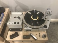
Ford E250 camper
- has "common ground" speaker wiring. Only one ground is shared between all speaker positives.

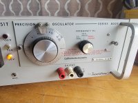
Alpine UTE-BT73 head unit
- has "floating ground", aka modern +/- speaker wire outputs.

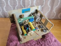
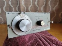
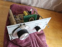
Scosche FGA floating ground adapter
- takes in 8 modern +/- speaker input (and a "ground" reference connected to headunit chassis) and outputs to the old school common ground system (4 speaker +, and one ground).
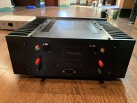
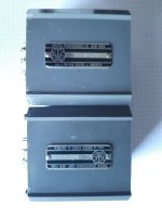
Alpine KTP-445A amp
-supposed to be plug and play with Alpine head units
-takes as input the entire harness from the head unit
-outputs the entire headunit harness as if it was coming straight out of the headunit, with a higher amplified signal on the "speaker-level" wires

---------------------------------------------------------------------------------------

Working setup without amp (1):
Headunit -> FGA -> car harness -> speakers

This is working great. Balance/fader works, all speakers are equally loud. If you disconnect the ground input for the FGA (connected to headunit chassis), then the audio gets a lot quieter.

Now, I am trying to add a KTP-445A mini amp to the setup.

Theoretical setup with amp in a modern vehicle:
Headunit -> KTP-445A -> car harness -> speakers

Non-working setup with amp and FGA (2):
Headunit -> KTP-445A -> FGA-> car harness -> speakers

This is not working properly. With the FGA still grounded to the headunit like it is in setup 1, there is almost no signal going to the FR and RL speakers. Most of the sound is going to FL and RR. If you disconnect the FGA's input ground, then there is seemingly equal audio signal going to all 4 speakers, but the fade and balance don't work properly (you can't isolate the audio signal to any one speaker). For example, if I set the the fader/balance all to FR, there is basically no sound at all. This also happens with the FGA input connected.

I have tried connecting the FGA's input ground to car ground, or to the amp chassis, instead of the headunit chassis, but the exact same thing happens. I suppose I could leave it as is with the FGA's input ground NOT connected since I don't really need fader/balance, but I'm afraid this could cause damage, or not be getting full power.

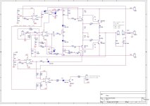
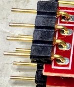
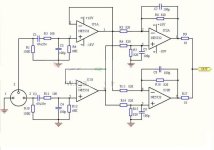
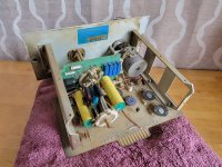
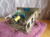
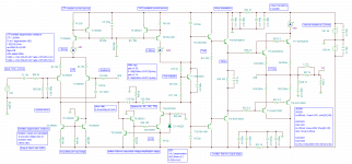
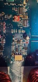
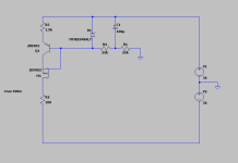
Side note: The Scosche FGA is very simple and only has some capacitors inside it. I initially had a different FGA: Peripheral FGA4. It had some extra parts in it (transformers?) and would actually produce heat! The Peripheral FGA worked just fine without the amp, but would not output sound at all with its input ground disconnected. With the amp, it would get quite hot with the input ground disconnected (and same non-working fader/balance), and with the input ground connected had the same problem with the sound going mainly to the FL and RR. I like the new Scosche one since it doesn't produce heat and waste energy. But I included this info as it could provide some clues.

I am trying to understand what's going on but it's difficult without understanding what a floating ground adapter does internally. @oPossum , it looks like you have some experience with these floating ground adapters as I saw in a different thread.

Can anyone shed some light on how a floating ground adapter works electrically and what it's supposed to do? Why isn't fader/balance working anymore? Why does sound go mainly to two channels when I connect the FGA's input ground like it's supposed to be? Where should I ground the FGA now that the amp is in the picture?

Hammond equivalents and substitutes for the Triad N transformer series (eg N-68X)

The Triad N-68X is popularly suggested as the fix (along a 3-prong cord and death cap removal) for AA4/5 radios and amps ("widowmakers"). In an old thread

https://www.diyaudio.com/community/threads/old-radio-quick-question-re-ps.85134/#post-988972

post #11, member Tubelab_com mentions some Hammond substitutes for the Triad:

Hammond 185D230
Hammond 185E230
Hammond 186E120

The Hammond 187 series is identical to the 186 except with a single primary. I'm interested in the 187 series as a substitute.

However Hammond lists the 169 or 171 series as substitutes for the Triad N series with no exact substitutes for the N-68X. Hammond identifies the Triad FD7 series as the match for the 186E120 and the F7 series for the 187E120.

I checked the specs of the N-68X and the 187E120 seem fairly close, especially the insulation rating and the hi-pot test. I'm inclined to think that using the Hammond 187 series would be safe. Also I can get it a little cheaper. So do you think it is safe to use the Hammond 186/187 series for isolation?

Assuming that the 187E120 is safe, would the 187D56 (56VCT,30VA) be safe for the build in the attached file (6N2P+50C5 amp).
Any and all comments welcome. Thanks.

Attachments

Active Ultra-Compact Near-Field Monitors and Subwoofer

Hello everyone. My first thread here on this great forum.

PROJECT: I am working on a ultra-compact near-field monitor pair with matching solo ultra-compact subwoofer. Intend to individually actively amp every driver, and feed them through multi-channel DSP. Also, intend to use only closed enclosures.

PRIORITIES: Loudness or efficiency in not a concern here, but sound quality, i.e. resolution, imaging and accuracy (in that order) at low to moderate SPLs are paramount. Application is purely musical, and hence very-low extension in not a priority, but no overhang or boominess is absolutely critical.

Seek suggestions on the following, with current choices highlighted against each: -

1. COAXIAL DRIVER: Can I find a good enough coaxial driver? How is Seas Excel C16NX001/F (E0080-04/06) Graphene cone? Or should I stick to the Magnesium cone variant C16N001/F (E0051), which is half the cost!? I am not really sure how good are the tweeters on these. Heard it may be possible to source KEF coaxial drivers, but not sure how?

2. MID-BASS DRIVER: If not coaxial, then suggestions for a good mid-bass driver which can work in a very small closed enclosure? I am inclined towards the Purifi PTT4.0M08-NAC-03. Look forward to better suggestions in the sub 1K USD per pair range.

3. TWEETER: A matching tweeter for the above? Need best possible resolution and imaging with sub 1K USD for a pair.

4. BERYLLIUM DOME: Inclined to a Beryllium dome tweeter. But confused on making a choice of exact make mode.

5. SUB-WOOFER: Suggestions for best driver suited for a small closed enclosure? Can spare up to 0.5K USD for one. Inclined towards SB Acoustics SW26DBAC76-4BLK 10 inch shallow driver due to closed-box optimised design and F3 of down to 35 Hz in a 1.2 cu-ft closed enclosure.

6. AMPLIFIER: Looking for discrete PCBs with modern Class-D designs, which I can put in my own chassis. Can do around 1K USD for the five channels of amplification needed. Suggestions please?

7. DSP: Need 8-channels for crossover and, if possible, room correction. An integrated DAC will be welcome. Inclined towards mini-DSP. Suggestions welcome…

Thanks for reading through and have a great day.

19KHz transformer for stereo demux

Looking for a replacement for L405 from a Sony STR-6060FW. This is a 19KHz tuned transformer with center tapped primary and secondary that feeds the diode frequency doubler. This type of stereo demux is so common I would expect these transformers to be ubiquitous, but my searches so far have come up empty.

Attachments

  • Annotation 2020-04-05 133827.png
    Annotation 2020-04-05 133827.png
    88.7 KB · Views: 415

BLE DIY solution with Audiolabs M-DAC

Hello everyone,
I am new to this forum. I hope I have posted this question in the correct fourm. I am hoping for some input on how to proceed with a solution I am working on.
Recently I have repaired an Audiolab M-DAC. I would like to add a BLE input. Preferably internal, with a cheap and small board. However external is However, I am uncertain what output would be the best option, either coaxial digital or SP/DIF? And would soldering the output internally instead of connecting externally be a solid choice to move forward?

Any advice on how to proceed?
I understand there may be too little info for good advice, so feel free to ask for any info needed!

Thank you in advance,
Jesse

Quick for sale: Verity Audio Fidelio in Glossy black. Price negotiable.

Good afternoon everyone. So I Need to sell these to pay a medical bill to be honest. It came up quickly. So I don’t have paper work or the box’s. I do have the floor spikes on them and the missing binding post screw in’s now.So now they are ready to use in your Home. Also the top right corner has a defect but, you can only see up close and is about a size between a dime and a nickel. All drivers are in mint condition and so are the front grills no snags at all. So I would like local pick up or I can meet up to save driving time. I can do apple pay so it shouldn’t cost anyone or cash with the trade or pay pal. So Am open to offers on these almost mint speakers in glossy black. Please send offers or questions to my E mail and I will respond back asap. This my E mail address. Jmboo1922@gmail.com. Thanks Jeff


New Update : The speakers have been sold. Thanks Jeff

Active Loud Compact 3-Way for Musicians and Performers

Hello fellow members. Starting with design/part choices for a new project.

Want to build an active DPS crossed-over active speaker system for performing musicians/ artists (particularly keyboardist and the one-man-band variety) with the following design objectives: -
1. Monitoring level sound quality (resolution, imaging and accuracy) for enabling critical practice sessions and recording.
2. Enjoyable listening experience for casual playing. Should be entertaining with smooth highs and punchy bass sans any overhang or booming.
3. Very compact size to be able to fit in modest rooms and practice venues.
4. Easy to transport and fast to setup. All components should be light and small to go in the boot of a car, and should be quick to connect up.
5. High output, to be able to perform live (multi-genre music) and do PA duties for small gatherings.

I am on the following choices so far: -

1. Design:
a. An active 3-day design (2 satellites + 1 subwoofer) with DSP crossovers and response correction.
b. All sealed enclosures. Need to avoid bass overhang at all costs.
c. MTM configuration for satellites.
d. Class-D amplification for efficiency, with dedicated enclosure for all amps and DSP.

2. Drivers:
a. Tweeter (1+1): Morel CAT 378 1-1/8" Soft Dome Horn. Very high output with soft dome sweetness. On the lookout for a compression driver which can be sweet and monitor level sounding...
b. Mid-Bass (2+2): Beyma 5P200nd 5" Neodium. High output in small size/ volume and good sound quality (though, very few reviews around to validate that).
c. Subwoofer (1 or 1+1): Eminence LAB12C 12". High power and can hit low in a small sealed box.

3. Electronics:
a. DBX DriveRack PA2 loudspeaker management system. AFS is an added advantage.
b. Custom-built amplifier with Hypex OEM modules.

X5HV - the F5 principle applied to a headphone amp

Have been working on this for a while, but here it is - a headphone amplifier based on the F5. In this case, with a few twists:

Designed for (Stax) electrostatic headphones, and will swing +/-250V at the output
Symmetric construction, inspired (but probably not as elegant) as the X5 from EUVL
No thermal compensation, but simple servos
The boards have voltage regulators on there as well

This picture shows the testrun I did tonight - I just had to try it, once it was up and running (and not smoking 😀) (well, almost no smoke 😀)

The two boards with heatsinks are the amplifiers, the other board is the power supply for the amps and bias, powered by a custom toroid.

Hope you like it, more details later....

Attachments

  • full amplifier testrun.jpg
    full amplifier testrun.jpg
    134.7 KB · Views: 2,467

3 way, sealed bass, OB/dipole mid, hi

I've been wanting to have a go at OB but I don't think my room/WAF will allow decent bass, so I built some bass modules. Initially I was going to build a compact 3 way into these cabinets. They are old Wharfedale Laser 100 boxes of about 28litres. Turned 90 degrees to how they were originally oriented and MDF applied.
My other speakers are XRK Ref Monitors so I have experience of RS225 and I bought another pair. I had swapped out the 3"FR in that build for a Morel CAT378 with good results.
So after much simming and reading I thought I had enough knowledge to 'have a go' and so it began. Pretty much cobbled together and used various values of XO components that were on the old Laser crossover board. Far from optimal but a start .
IMG_20230323_192532.jpg
First iteration above with SB15NRXC30-8 and SB29RDNC.
This with 3.7mh and 25uf on the woofer as per the Laser Xo which is about where I wanted to be. Mids were 1st order electrical HP of series 16uf and LP being 0.8mh, 8uf. HP on tweeter was 6.8uf 0.3mH. Padded down about 6db.
Initial impression were that it 'worked' but was a bit bright. I tried padding the mid and also upped the HP on it to 50uf to push them lower. Sounding decent now but I think the break up of the SB15 is causing the brightness.
I remembered I had some RST28F in WG300 so I tried that as a 2 way.
IMG20230330162638.jpgIMG20230330162622.jpg
It's good to have an external crossover to be able to swap bits in and out easily! Not sure the wife is so thrilled at this point!

So maybe I should be deciding exactly what I want to build now but the 3 way was still an itch so I went back and tried me a bit of a dipole naked setup .

IMG20230402152953.jpgIMG20230402153010.jpg

Having read the dipole tweeter thread and seeing the use of small and cheap Vifas, I had already bought some and employed them here now. BC25SC15-04 on the front for improved WAFnand the OC25SC15 on the back. Doesn't give as small a dipole distance as 2 OC back to back but looks better. Wired them series + to - but I'm not sure if that's correct. I think the rear membrane should move in the same direction as the front firing one. Here it will fire backwards as the front fires forwards.
HF circuit now modified for 8 ohm as the 2 4ohms in series, so now on 3.3uf and I think 0.56mH. I am aware these tweeters have quite high FS so I'm probably pushing them a bit with this approx 3k HZ filter. Can't hear anything untoward from them mind . The main issue as I look at the data sheets is the the SB15 won't cross nicely to the tweeters up at 3k. They start to break up fast after 3k. I considered a notch filter but remembered I had some Seas MCA15RCY. These look much flatter and so they went in next. Now we're getting somewhere. Sounding nice!
IMG20230407173522.jpg
I keep playing with the series cap on the mid, I've pushed it a bit lower to meet the RS225 with a 50uf. Having read a bit more on dipole I understand with a calculation that the mid should be rolling off 1st order at about 1100Hz. (172/ 0.15m). The 50uf should be rolling it off again at about 450hz. I removed the padding on the mid. All this being done by ear and looking at the data sheets and playing with XSim. I might try 1st order LP on the mid with 0.3mH and simming a lower value HP cap on it gives a much sharper reverse null.
I can hear the groans of dissaproval if no measurements but I find this iterative approach very interesting and informative. I've learned a lot. But I have bought a Dayton Audio microphone and do intend to see what sort of mess I've created! They do sound very nice. I'd like a bit more bass and know it's there so probably crossing nearer to the baffle step frequency and attenuating the upper 2 drivers is in order. But I dont know if the naked MCA15 will do that if it's rolling off at the dipole frequency of 1146Hz.
Latest XO below.


IMG20230407173552.jpg
I have some newer bigger guage Monacor 3.9mH inductors to try on the woofer. Much lower DCR. And I'll try a film cap on the mid. It's been handy this old Wharfedale crossover! That's the story so far. Thanks for tuning in and I'll update accordingly.

*** JFET: LSK170A and LSJ74A to sell****

I have bought many LSK170A and LSJ74A from Digikey recently in orde to match N and P channel. LSK/LSJ is the replacement of old Toshiba 2SK/SJ transistors. Unfortunately I was not so lucky for the matching N and P but maybe I have some transistors that may fit your need, either:
  1. you only need one type (N or P ) but you want a matched pair or quad or octal or more. I can match them for you. You can build for example Fc-100, Goldmund Telos/Mimesis or other Diy Pass forum amps or preamps using K170 or J74 as differential input .
  2. you already have N or P and you are looking for a match For a symmetrical input amp.

Available LSK170A : no more available
I also have LSJ74A with IDSS from 3,25 to 4,77ma.

I can provide the matched IDSS you need Within above range. You can specify at what voltage too for measurement. I can also match at the real application ID current too.

Price for each jfet is 4$ USD (matching included). Shipping price to be determined upon country destination.
At that price I need to apply a minimum order of 6 transistors otherwise it is too much work and trouble for so less money….😏
For smaller order, please contact me to establish a fair price (it will be lower that diyaudio store price).🙂

Fab

Attachments

  • IMG_4505.jpeg
    IMG_4505.jpeg
    472.5 KB · Views: 166
  • IMG_4504.jpeg
    IMG_4504.jpeg
    443.9 KB · Views: 167

For Sale Sony TTS-2000 for restoration

I have a Sony TTS-2000 belt drive turntable that I purchased for restoration. I'm moving in September and need to make room (we're downsizing). This is sold as-is with no returns or guarantee. The seller said it works but I haven't tested it. I think I have a belt but am not sure. I believe it's complete - i.e. no missing parts (except possibly the belt).

$50 plus actual shipping cost.

I have several tonearms that could be paired with the table.

DSC_7317.JPGDSC_7318.JPGDSC_7321.JPG
  • Like
Reactions: matsurus

Auralic Aries G2.1 Power Supply PCB.

Hello!

I am searching schematics,good pictures and components list of Hoer-Wege modded power supply pcb for Auralic Aries G2.1.

I am allredy have Talema transformers,ultra fast schottky diodes and Schaffner power line filter.
I need to know more information about another components and hoer-wege pcb schematics.

If someone have pictures of it in bottom and upper side,then please send it to my email: audimees@gmail.com or post here.

GB: Round #8; Fo-Felix AC Filter

**We're on round #8!!!**

I've confirmed how to order parts, made sure it isn't an issue for Comocos. (please no more requesting samples)

So over the years people have asked about the old version, made by someone else.

It's probably time for an updated one. This one is a bit different. You may notice it does not have following capacitors after the choke. I have tried both ways, and my preference is strongly without the following X2 capacitors. Also the capacitors prior to the choke are not varied in size because overall capacitance is more important - and they won't randomly resonate with each other.

The other major change is the addition of bypass resistors for the chokes. These don't ruin the filtration, but they do a good job of quieting the chokes that can get excited by different combinations of things on the mains.


Fo_Felix_R2_Public_preview2.png


Gen1 w/comoco's
IMG_1974_1_22.jpg


Here's how it is different in settling time from the original.
Fo_felix_vs_felix.png


Here's a comparison between resonances.
Fo_felix_vs_felix_resonance.png


*2oz copper PCB (1oz is standard)
*Weco 983ZD terminals, copper alloy and can accept 2 wires for daisy chain. These are also safer, particularly if you use solid core wire that otherwise likes to make cold solder joints you can't see.
*X2 rated capacitors for safety, 4x 0.47uf. They are alternated for CFC (capacitor field cancellation).
*Discharge resistor for X2 capacitors
*Coilcraft Comoco choke w/fuse or Bourns 8120/8121-RC choke w/o fuse & 15/16A/20A(*) max sockets
*Fuse clips are beryllium copper (good for 30A)
*120/230v operation (parts & pcb)
*Mounting holes are sized to work nicely with M3 screws and standoff kits
*Size: 2.25x4.25in

The Weco 983ZD are preferred terminals, but not always available as individual sale. For this reason I'm going to include them in the price of PCB, so that I can meet min order requirements for them and save everyone the shipping.

Price: $13ea ($9 per filter board same as original, $2 per Weco, 2 needed per board)

Shipping: $10 US, priority USPS box
$18 CAD
$20 General international padded envelope (prices may vary due to a crazy world)

If ordering over 4x boards there may be an additional $10, depending on destination.

Need 32 filter board commitments to order.

vanofmonks 4
Rogster 4
Ian54 5
Lance 5
finwbu 12
meanie 4
pedrop 4
sq225917 2
dantwomey 2
dirkrs 14
Cambe 4
sanjeev 4
lucser 4
Bas Horneman 2
SolidCore 10
sierra_gva 10
limits 6
HiGHFLYiN9s 2

**Full

I am building a portable 3W Mono Bluetooth speaker

I am building a bluetooth speaker, this is my first audio project and I am not sure about some things, can you all help me out?
I want to know how is volume control implemented in an audio amplifier. In various datasheets I have seen that there are only 3-5 options for gain control but speakers usually have more volume levels.
Maye I am confusion volume control with gain control. How is volume control implemented ?
Can you suggest some good amplifier ICs?

Carlsboro hornet custom 35w

I have inherited a large Carlsboro Hornet Custom 35w amp with twin 12” 20w celestion speakers.
It works well, tremelo, presence, etc.it has one fault…it just dies after 10 or 15 minutes use.
I really need a schematic, but I can’t find this model !
willing to pay for a circuit diagram, and would appreciate any advice re the caps!
Mike, Hinckley, Leics,Uk
i can send a pic if required!!

Help with DC offset in Single rail QC amp?

Hi, I bought an amp a while ago (had a few of them in the past -Audio Innovations Alto MK1) and over last couple of days as it gets warm it starts to sound a bit rough.
When I first got the amp 2 Months ago) I checked DC on the output which was less than 10 mV, so fine, I thought. But, today I decided to check it again and it was @45mV and rises to 1.4V after 30 minutes on both channels.
The amp is a kind of rehash of of an old single rail quasi complementary design and uses a pair of 2N3055 and an output capacitor.
I don't believe the amp has had any work on it since it was first sold , approx 1996-7.
I tested with a DMM across outputs with nothing else connected, is this correct? Is there a fault?

Attachments

  • ALTO4.jpg
    ALTO4.jpg
    191.1 KB · Views: 126

Heathkit W4-AM amp

A few weeks ago the power transformer on my recently acquired W4-AM amp bit the dust. It looks like finding a used replacement may be very difficult and expensive if even possible. So I am wondering about trying to extract the core and consider rewinding it. I have never tried to un-pot (is that a word?) one of these old transformers. Is heating the only way to do this? What kind of temperatures are necessary? Could I let it soak in an oven for a couple of hours to soften the potting compound (tar?). Alternatively, it there a chemical that would dissolve the potting? If anyone has experience with this I would greatly appreciate your sharing your experience and wisdom on this. Thanks.

Bill

Orion HCCA 1200.2 OutPut resistor question

So I replaced the blown bond resistor, noticed the FETs were mismatched from a previous repair (stickler for my gear running as prime as possible) so decided to swap out all the output FETs (TIP35c/36c) from the lesser version to the better ST, matched set, and just got done looking over my joints (haven’t even cleaned flux off the board yet) and noticed this amp is either missing 2 resistors in the TIP35C section on each half or empty but mismatched areas from factory? I tested amp after bond resistor replacement before FET change out and it seemed to run great at idle, so I’m guessing this was in purpose from factory? Why are they not in same exact area on each side? Did the previous tech who repaired the first blowout using mismatched batch/brand FETs remove them? Each resistor is 22 Ω and even the empty resistor sockets probe are 22 Ω as well.

Just trying to make sure the amp is running proper, and this just doesn’t look right, if it was from factory I’d expect it to look the same on both halves of the board, any info/insight would be greatly appreciated. Resistors of concern/empty sockets circled in blue.

Also depending on answer, can I move the one resistor that isn’t on one of the 2 outside FETs to the outside to match the other half of board? Just OCD preference, lol, just looks as if location doesnt matter just as long as 2 are there like it looks, placement looks random 😅 unless there is 2 from each side in fact missing 🙃 or would it be better to have the resistors as populated/unpopulated/populated/unpopulated or like I 1st mention as populated/unpopulated/unpopulated/populated …I know this may be overthinking but still would like to know 🤓

Thanks guys 🖖🏼

Attachments

  • 28ADAE86-1388-4ECF-BD6E-D777BB8995C2.jpeg
    28ADAE86-1388-4ECF-BD6E-D777BB8995C2.jpeg
    499.7 KB · Views: 107
  • A234CDE3-EDE7-48C7-8EFD-2CBB21EF871A.jpeg
    A234CDE3-EDE7-48C7-8EFD-2CBB21EF871A.jpeg
    667.4 KB · Views: 93
  • 0C7013BC-E4A9-4C14-9D24-4357B76476CD.jpeg
    0C7013BC-E4A9-4C14-9D24-4357B76476CD.jpeg
    526.8 KB · Views: 97

Help needed in scoping out a low power integrated amp using B1 Korg

Hello Guys,
I would like to harness the forums braintrust if I may to help with a low power integrated amp. scoping .
I would like to see if it is doable , by using off the shelf diyaudio projects or other reputable boards .
So it starts like this : I would like to use the B1 korg pre-amp , since I am looking for that tubey sound (the tubier the better).
My media source should deliver around 2v peak to peak audio into the B1 .
And I would like to have around 5W RMS per channel into 8 ohms in the output .
‘So the question is what do we need to do to get B1 to 5W ? The simpler the better.
All of this : B1 preamp , power supply (linear) and the cct to get the 5W will need to fit into one nice compact box .
‘Well , relatively compact .

Much appreciate your help.
Mil

Harman Kardon Citation 16 Upgrade

Our audio shop has closed due to retirement and I would like to share our mod for the HK Citation 16 & 16A. I hope that this will help some of you who would like a little better sound quality but the mod will improve clarity first and foremost.

Attachments

For Sale Tubes

ALL SOLD
test good and look nice with no shorts
5 GE 12BH7$25
3 Sovtek 7025 12AX7A $45
Pair test NOS Sylvania Baldwin 12AX7 17mm plates $55
1 Sylvania JAN 5751 2 mica $20
4 German RFT ECC83 test strong $80.
Raytheon VT-231 JAN CRP 6SN7GT test NOS 92/60 95/60 on TV-7 $50
801 with micanol base, ceramic supports, name illegible tests 95/60 no shorts, nice getter $40

Attachments

  • F766FC2E-836F-47F6-9760-637CA409BAC2.jpeg
    F766FC2E-836F-47F6-9760-637CA409BAC2.jpeg
    333.9 KB · Views: 79
  • E9756025-1AAA-4765-B47B-3F3556816231.jpeg
    E9756025-1AAA-4765-B47B-3F3556816231.jpeg
    397.8 KB · Views: 71
  • E65AFF8C-7FDA-438F-910D-91B9C02553FA.jpeg
    E65AFF8C-7FDA-438F-910D-91B9C02553FA.jpeg
    789.2 KB · Views: 56
  • B47CDB05-5D1A-496F-9075-17D0DB77FB2E.jpeg
    B47CDB05-5D1A-496F-9075-17D0DB77FB2E.jpeg
    655.3 KB · Views: 60
  • 1483F4A8-D8F6-4D96-88CC-6A0D6FDC6812.jpeg
    1483F4A8-D8F6-4D96-88CC-6A0D6FDC6812.jpeg
    592.6 KB · Views: 65
  • Like
Reactions: Ite

Amari LP -82 speed Pot recommended replacements

Hello all,

I have an Amari LP-82 turntable, it is basically an Micro- Seiki RX5000 clone. I’m finding it difficult to get the exact 33.33rpm when using the fine speed adjustment. Does anyone have a suggestion for replacement speed Potentiometers that would make fine tuning the speed a little easier?

Thanks in advance

Attachments

  • 278AF160-E650-4F4F-A9FB-C7E71B23E874.jpeg
    278AF160-E650-4F4F-A9FB-C7E71B23E874.jpeg
    363.5 KB · Views: 232

Seeking Advice on a Custom LXmini Speaker Project!

Hey fellow audio enthusiasts,

I hope this message finds you all well. I wanted to share an exciting project I'm planning for my office desk and seek your valuable advice and expertise. I've been inspired by the renowned LXmini speakers, and I've decided to build a variation of them tailored to my specific needs.

Here's a breakdown of my project plan:

Enclosure: I intend to 3D print the enclosure for this speaker project. This approach should give me flexibility in terms of design and customization while keeping costs reasonable. I'm looking forward to experimenting with different materials and configurations.

Woofer Driver: For the low-frequency driver, I've chosen a 6.5-inch unit from Mark Levinson. I believe it will provide a solid foundation for the speaker system, offering good bass response and overall performance.

Full-Range Driver: To handle the mid-range and high frequencies, I'm considering two options: the GRS PT6825-8 or the GRS PT2522-4. Both drivers seem promising, but I'm open to suggestions or experiences you may have had with either of them.

Amplifier Board: To power this speaker system, I've selected the TSA8804 DSP-enabled amplifier board. Its integrated digital signal processing capabilities should allow me to handle the crossover function effectively and fine-tune the sound to my liking. I'm excited about the possibilities this board offers.

Now, I come to you, the knowledgeable and passionate audio community, for your guidance and advice. Here are a few areas where I would greatly appreciate your input:

1. Enclosure Design: As I embark on 3D printing the enclosure, what factors should I consider to ensure optimal sound reproduction? Are there any specific design principles or techniques that I should keep in mind? Any recommendations on enclosure volumes or materials that have worked well for you in similar projects?

2. Full-Range Driver Selection: Between the GRS PT6825-8 and GRS PT2522-4, which driver do you think would be the better fit for this project? Are there any other alternative drivers you could suggest? I'm particularly interested in achieving a balanced and accurate sound reproduction across the frequency spectrum.

3. Amplifier and DSP Configuration: Since the TSA8804 amplifier board features built-in DSP, what are some key considerations I should keep in mind while programming the crossover function? Are there any recommended crossover frequencies or other DSP settings that I should experiment with to optimize the speaker's performance?

4. General Tips and Recommendations: Lastly, I would love to hear any additional advice, tips, or recommendations you may have based on your experience in speaker design and DIY audio projects. It could be anything from wiring considerations to potential tweaks that could enhance the overall sound quality.

I'm truly excited about this project and can't wait to dive into the world of DIY speaker building. Your collective wisdom and expertise would mean the world to me and help me make informed decisions throughout this journey.

Thank you in advance for your valuable insights and suggestions. I look forward to hearing from all of you and sharing updates as this project progresses!

Best regards,

Baker
Projects by fanatics, for fanatics
Get answers and advice for everyone wanting to learn the art of audio.
Join the Community
507,700
Members
7,884,895
Messages

Filter

Forum Statistics

Threads
406,067
Messages
7,884,895
Members
507,700
Latest member
Tomasz 026