Using Hypex Fusion Amps FA123 with old MTM towers

Hello, I'm planning to replace the old amplifier/DAC pair and drive an old pair of high quality passive tower speakers plus a passive sub using a pair of FA123s (that's my budget).
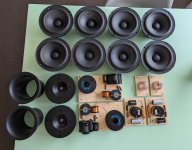
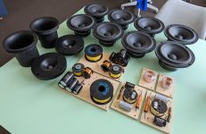
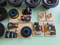
Advantages: I can drive the amplifier stage directly in digital, vary the response curve and cross towers and subs with few phase problems. The towers are two MTMs with a pair of Vifa P17s in parallel each and a Morel tweeter, the sub is a single Peerless XXLS 10'' 830846 with 8+8 ohm dual voice coil.
The problem is that to align the sensitivities of the two 4 ohm MTM towers with that of the sub, I estimated that for the latter I need more than 4 times more power than that of each tower.

Solution A: I could bridge the two 125w stages of each FA123 and drive the sub with a total of 500w, using the 100w stage of each FA123 x each tower, which will continue to work with its passive crossover. However, I did not understand if this stage is qualitatively inferior to the 125 ones since its power does not change according to the impedance (100w@8 / 100w@4) as happens correctly for the other two (75w@8 / 125w@4 ). Will this stage have a lower current reserve and will therefore not be as good in transient response? That should be the best quality stage for me since I have to drive the towers at almost full range!

Solution B: I would have preferred for each FA123 to use one 125w stage for half sub and the other two for the single ways of the towers, piloting them as an active crossover and exploiting the full potential of this technology but unfortunately I fear that I would have to lower their level too much to align them with the low sensitivity of the sub.

In any case, I would still have a good infrastructure in hand to use for future new systems to be self-built such as WWMTM or WMTMW.
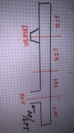
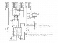
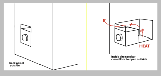
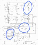
Following a scheme of two solutions:
img20230110_22474290.png


Here are the questions:
1) ultimately what could be the best solution in your opinion, A or B, considering also that my extimations might be wrong?
2) how do the Hypex FA modules 'sound', in terms of audio quality?
3) which input digital formats are they able to deal with?

Any suggestion or personal experience will be welcome, thank you!

B&O Icepower 200ASC 200AC repair?

Has anyone had any success repairing B&O Icepower 200ASC 200AC modules? I have a handful of them all with various issues. no output, low output, half volume output, low 47V output etc etc. none of them have any visible issues like burnt parts, signs of stress etc. curious if these have common issues that are repairable or should i just toss them in the bin?


ZC

Metal shop in Australia

I want to make a small metal panel for a chassis top. This is perfect for Front Panel Express.
However, I live in Australia.
Is there a shop in Australia that provides similar services as Front Panel Express?

Update one week after..................
I was not specific enough in the original post given most of the replies.

I have also changed plans and found that Modushop, which caters to diyaudio folks, offers what I think I need at a reasonable price.
Front Panel Express was fine for what I originally wanted, but the shipping cost was 50% more than the cost of the panel.
I was just hoping more for a personal referral to an Australian shop, rather than how to find one.
Anyway, thanks for the replies.

Thanks

Repair Cyrus dAD7

I'm looking for the service manual to repair the dAD7. Unfortunately, it appears that someone else has been poking in it and it's no longer original 😔. Perhaps someone can have a look at the photo to see if modifications are reversible. The CD player only plays the last two tracks and makes a terrible noise when trying to play the other ones (hard clang).

Attachments

  • IMG_20230607_185506.jpg
    IMG_20230607_185506.jpg
    530.7 KB · Views: 443

Advice Sought about possibility of Balanced Input Power amp

I can't believe this info isn't available somewhere but I've spent several days trying to find it.

I have an ageing AVR that isn't much use to me any more, not really interested in surround sound movies, no interest in going to atmos. So I'd like to get rid of it and have better sound, especially surround sound audio. Main speakers are Kef iq7, also have cheap centre speaker & decent rear speakers, which I'd like to keep for the time being and consider replacing in the future.
I have a spare Raspberry Pi no longer used from another project which I'd like to utilise with CamillaDSP for output.
I'm interested in purchasing a Topping DM7 8 channel DAC. If I do, my use case would require several power amps (bi-amp front speakers, centre speaker, stereo rears) with balanced input, balanced because of the DAC output.
I'm OK at electronics, IOT devices, soldering etc. Own an oscilloscope, own and read a couple of Douglas Self's books. Have had a long-term wish to self-build some amps, which I've never done.
My question, which I'm finding pretty hard to answer for myself: Is it reasonably do-able to build any of the forum amps, (eg the Wolverine amp but any others might do) with XLR/TRS balanced input or with some kind of balanced input stage before the amp proper?

Old 3,2 ohm speakers with old TCA940 IC amp board

hello guys!
I would like to ask you if it could be dangerous to connect with a low impedance value (3.2 ohm) old speakers to a small old amplifier based on the vintage I.C. TCA940.
I would like to specify that 3.2 ohms is not the resistance of the speaker but its actual impedance.
I also wanted to ask if by changing the tweeter with another one with an impedance of 8 ohms (and therefore also replacing the high-pass capacitor with another one with a greater capacity) I would be able to increase the general impedance of the whole speaker (at least) a little. Thank you very much. Best regards.
1690787557237.png

1690787484567.png

Marantz PM - 64 Mk 2 right channel out

This amplifier has no output in right channel , so i measured voltages on stk module 3102 mk 3.
Voltages seems okey besides pin 10 , 11 and pin 5 , 6 that measures between 0 - 200mv.
Theeses voltages are inbound to stk?

Tried headphones with same result...only sound left channel.
Q 715 and Q711 area seem to run varmer that the rest of the outputs.
Suppose my next step is to go upstream from q715 side and measure voltages , but i was not sure the stk module could be the reason for this.

Would be grateful for any pointers.

Here are readings from output transistors

Q 715 E 70mv , c 36v , b 655mv
Q 711 E 67mv , c 35.8v , b 650mv

Q 713 E - 103mv , c 35.8v , b 665mv
Q 717 E - 87mv , c 35,6 v , b - 665mv
Q 718 E - 265mv , c - 35,6v , b - 575mv
Q 714 E - 275mv , c - 35,7v , b - 582mv

Q 712 E - 280mv , c 35v , b - 586mv
Q 716 E - 280mv , c 35.7v b - 585mv

Attachments

  • Polish_20230701_153150690.jpg
    Polish_20230701_153150690.jpg
    301.9 KB · Views: 192

Low power TPA3255 and DSP

I built an active speaker with a 24V battery some time ago, a DSP ADAU1701 and two TPA3118 and it sounded quite good and loud. I wanted to increase its power and I bought two TPA3255 but the problem is that it has not increased as much power as it should and investigating I have discovered which is because the input sensitivity of the amplifier is 2Vrms and the output of the DSP is 0.9V is there any way to decrease the input sensitivity or increase the output of the DSP? Would it help to change the OP Amps? The specific amplifier is this
Acabo de encontrar este increíble artículo en AliExpress. ¡Échale un vistazo! 21,69€ 27% dto. | Placa amplificadora Digital de alta potencia, TPA3255, 2,0 DC24-40V, 300W + 300W, Clase D
https://a.aliexpress.com/_mOGPHeg

Need help choosing a DC blocking capacitor

I built a LM3875 chipamp from Audiosector years ago and added a discrete buffer circuit from Decibel Dungeon. See link below.

http://www.decdun.me.uk/gainclone2.html

I just realized after all these years that I'm supposed to add a DC blocking capacitor to the input and output of the discrete buffer circuit. Which value capacitor do I use? Would a 1uF polypropylene capacitor be ok?

Some questions on 805 Tubeamp circuit design and testing

Recently, I purchased a diy kit of high power class A tube amp based on 805 (shugang FU-5). However, there is no assembly instruction except that they can only provide the schematic diagram and some photos of the finished product. Although I have some previous assembly experience of a low power tube amp based on 6L6GC before, I don't have experience for a tube amp that operates at as high as 1120V. So I have some questions on the circuit design of this amp especially for its HV power supply and its filtering. Also on how the appropriate testing procedure should be.

1. Regarding the HV power supply (1120V), 3 HV caps(180uF 450V) in series. Just wonder if the withstand voltage 450V is sufficiently safe for the shared operating voltage 370V? Supposed I'll add a resistor in parallel with the cap to ensure the voltage is equally shared. Or would it be better to add one more cap (i.e. 4 caps in series) so that the shared voltage will be less. Hence better margin?

2. About the LC filtering. 3 caps in series so that the combined cap will become only 180u/3=60uF. Just wonder if the hum noise is too large? Should I use larger cap value (say 1000uF instead of 180uF)?

3. There is a 100 Ohm VR at the cathode of FU5(805). Just don't know its function? How are we going to tune this?

4. For the filament supply for the FU5(805), there is a 0.1 Ohm in series to provide 10V filament voltage. Is it for the power up delay?

5. As the FU5(805) is directly heated and DC coupled from 6L6, any precaution on the testing procedures?

Need advice from someone who has experience on this kind of HV tube amp. Thanks.

Attachments

  • tubeamp_FU5_schematic.jpeg
    tubeamp_FU5_schematic.jpeg
    140.3 KB · Views: 860

Boston Acoustics VR965 woofer issue

I just picked up a pair of Boston Acoustics VR965. I auditioned them before purchasing, and they sounded great, but when I plug them in at home the woofer in the left speaker is not firing properly. There is some audio coming out, but much less than on the right, and very noticeable in the stereo image. Occasionally, it will cut into the full signal, but then lose it again. There is some electrical noise and hum audible through the passive radiators, it’s not much but it’s there in the left and not in the right.
I took the woofer out and inspected it, I’m no speaker technician, but connections seems okay. I’ve tested with a different amp and speaker cables and same thing. Just wondering what I should do? Is it a case of needing a new Woofer? Anything else I should try?

antibump

buongiorno a tutti

lo schema per l'antibump non funziona con dei vecchissimi rele Siemens che possiedo da moltissimi anni (allego le caratteristiche).
mi dite come deve essere corretto lo schema per poter funzionare con dei rele siemens polariozzati?

Grazie

Guido Bullo

Buongiorno a tutti

lo schema antiurto non funziona con relè Siemens molto vecchi che possiedo da molti anni (allego le caratteristiche).
sapete dirmi come va corretto lo schema per poter lavorare con relè siemens polarizzati?

Grazie

Guido Bullo

Attachments

  • 555-f14.jpg
    555-f14.jpg
    86.4 KB · Views: 192
  • V23042-1_Siemens ab_Pagina_1.jpg
    V23042-1_Siemens ab_Pagina_1.jpg
    502.9 KB · Views: 126
  • V23042-1_Siemens ab_Pagina_2.jpg
    V23042-1_Siemens ab_Pagina_2.jpg
    324.4 KB · Views: 126

Bryston 4B power amp - help needed.

Hi All,

I need some help with a Bryston 4B power amp. Can anyone tell me what the function of the highlighted portion of the circuit does?


20220609_160831.jpg
The reason I'm asking is I accidentally damaged one of the Tantalum Capacitors (1.5 uf, 35V).

I got a replacement from from Mouser (Kemet T350K035AT), but I noticed that the origional cap has an ESR of 1.5 ohms, while the replacement's ESR is 9 ohms on my meter.
image.php

I just need to know if the higher ESR will matter, or is it irrelevant in this particular application.

Also, would a WIMA stacked film capacitor be an acceptable alternative in this particular application?


Appreciate any help
amnesia

Darlington Amplifier

Hello gentlemen, for some time I have wanted to build an amplifier with darlington transistors, on the web I have found few diagrams and the one that has attracted my attention the most is this because it has components that I easily get in my country (I live the third world) I was wondering what they think of the scheme.

Attachments

  • FB_IMG_1607567748465.jpg
    FB_IMG_1607567748465.jpg
    35.9 KB · Views: 3,942

Henry P. Hall passes at 95

Henry P. Hall worked for General Radio Corp. and was the impedance guru behind many of their classic bridges. Until recently he could be found in the groups.io GenRad forum, answering questions on anything GR related. I emailed with him many times over the years and he remained sharp as ever until the end. Super nice guy and will be sorely missed. If you measure individual components, Henry was certainly involved somewhere along the line that led to the equipment you use.

https://www.wickedlocal.com/obituaries/pneo0533462

FS Used Hakko FX-888

SOLD - Used Hakko FX-888 solder station for sale. Solder pen cable connection to base is a bit loose and requires wiggling every now and then to keep power to the pen. Otherwise in good working order. Includes solder pen, solder pen stand with sponge, separate coiled brass sponge tip cleaner and a few extra tips. Ship to US only. Asking SOLD plus shipping and Paypal fee.

Hakko_FX-888.jpg
  • Like
Reactions: Mikerodrig27

NAD C320bee DC issue Please help!

Hi Guys,

Having a bit of an issue with an amplifier I'm trying to troubleshoot. It has a reading of 0.300v on the right hand channel and I believe this is causing the amplifier to not turn on. Its just orange light.

Here what I know and what I have done:

The bias seems to increase on both channels just fine
The DC on left channel measures around 60mv at L21
The DC on right channel measures around 0.3v at L11
Q16,17,18,19 was swapped with working (?) channel
Emitter Q19 to Collector Q17 measures -28. other channel -38
R123 measure 0.3v
R115-116 where they meet also measure 0.3v
Not a single bad resistor! (I measured personally :yikes: )
Already been fully recapped but problem persists..

Thats as far as mine and my friends (owner of Nad) ability goes to troubleshoot this..

Any help appreciated..

Attachments

  • nad1.jpg
    nad1.jpg
    521 KB · Views: 265

Croft Series X info

Hi all.
I´m newbie posting and I´m finding some help. I´m doing this same question in other forums.

Two weeks ago I received from a friend a Croft Series X amp.
I can´t find any info on internet about this amp, and want to ask if somebody can tell me something about the schematic, tubes, etc..
I tested it and the volume is very low, I don't know if the tubes are what they should be and if they are in the right place (have 2 12AU7, 2 12AX7). This use 6080 tubes in the power section.

I send it to a tech guy and he tell me exactly "sell that, it is a circuit that demands a lot from the valves, it is very hot and since it does not have transformers at the output, the speakers are at risk".
I see the amp in original condition, very neatly and I would like to investigate well before making a decision. I would rather keep it if everything was fine.

Many thanks

Multiple stubs in QW pipes?

If I put a stub in a 300cm TL as L12(100cm) and add the stub as L45(60cm), I get rid of the second and third resonances (300/3 and 300/5 shown as red arrows.

but what are the new yellow resonances created (by adding the 60 cm stub at the end? )

Attachments

  • 0F90E26C-D0D4-4B7D-AA97-DD66FB59C5C1.jpeg
    0F90E26C-D0D4-4B7D-AA97-DD66FB59C5C1.jpeg
    649 KB · Views: 111
  • 637A28B0-E03B-4AA6-A257-4733D6A18CD0.jpeg
    637A28B0-E03B-4AA6-A257-4733D6A18CD0.jpeg
    497.8 KB · Views: 123
  • 574592BF-F66B-4011-83CD-0E882A80BE1E.jpeg
    574592BF-F66B-4011-83CD-0E882A80BE1E.jpeg
    597.5 KB · Views: 109

Missing Reverb Tank

Hello, new user here, I am restoring a 1960s Hohner Symphonic 310 Organ, and somebody took the reverb unit out of the organ, so I'm trying to find a replacement.
I was able to get the schematic from Hohner but they didn't have any info on the reverb unit.

I was wondering if it's possible to determine the characteristics of the reverb tank based on the schematic of the reverb amplifier?

the input transformer has printed Bv 30-68, don't know if that helps. I can provide the full schematic if necessary.

Symphonic 310 reverb unit.png

LL1660 parafeed phase splitter?

Hello all. I am trying to clear out my overstock of parts and I came across a pair of LL1660s (not the s variant).

I would like to use them as a single ended to balanced phase splitter to drive a pair of 300bs, but I have read that the Alt-V connection on the data sheet is not very well balanced which is why they came out with the S variant of the 1660.

My thought is that if the A and B windings are not well balanced, could I put all the A and B windings in series as a parafeed primary and use the C windings to drive the grids of the 300b? Would the C windings be more balanced for phase splitter duties?

cheap aliexpress/eBay ADAU1452 development boards

there's a bunch of cheap adau1452 boards on aliexpress and ebay lately.

aliexpress

ebay

some of them come with daughterboard "4IN8OUT_CODEC", some do not.

it was not obvious to me that you need an extra device to interface with the board, a USBi interface. the ADAU1452_DSP comes without the 2x5 header pins installed, which baffles me as to how they intended this thing to be used without it!

the official EVAL-ADUSB2EBZ interface can be used, though it is a bit pricey.

there appear to be cheap chinese USBi clones on aliexpress. not sure if they are compatible though.

the ADAU1452_DSP boards come with several empty spaces on the board, from the schematics it appears they are missing an STM32F103C8T6 (IC6), a 23LC1024 (IC7), and an 8mhz crystal (X2).

Advice on DHT B+ Ripple magnitude?

Hi all, I'm looking for guidelines on B+ ripple magnitude in a DHT output stage that will have about 220V B+. I have read previous threads and posts such as this one, and found them somewhat useful. I'd like feedback on the following design and suggestions.

With the below inductor input design, I see about 90 mV ripple peak to peak over about a 5 second window. I'm aiming for about 200V on B+ and, for now, the diode bridge is just a stand-in for what will eventually be 6AX4. The initial current surge through the first inductor is below the max rating of the 6AX4, and the circuit seems reasonably well damped with no major overshoot and some initial oscillation that settles in under 1s. The Hammond chokes are highish in DCR.

Feedback much appreciated.

Screen Shot 2023-05-08 at 8.52.34 AM.png


Screen Shot 2023-05-08 at 8.56.37 AM.png

Beyerdynamic A1 clone gold, opamp rolling

Hi, i'm searching some info about rolling opamps in A1 clone gold and this seems the best place to ask about.
I have replaced the stock opamp with a BB2132, at home i also have BB2107 and a TLE2062CP, should i try this opamps?
And, sorry but my electronic background is poor, what are the characteristic that i have to consider on rolling opamp for the best match with A1 amp?
Thank you

Thougts about PCB grounds and decoupling

Hi there,
I was attemping to design a PCB for Rod elliott's state variable crossover, 2-way (i hope its ok posting as he doesn't offer this on pcb).

In this circuit you have 3 "grounds" which are the input, output and PSU. The PSU will be already properly filtered, so i just added 0.1uF between Vcc and Vdd pins and ground. I know the rule about .1uF between PSU op amps pins and GND, but, i had the feeling "where" those PSU currents would be flowing would alter the circuit.

1)In the image for example The red circled cap is put there so its the closest as posible to the psu GND because the trace aint that long to begin with. Otherwise the cap would decouple straight to in and and out GNDs. Should it be moved?

2)In the green circled cap the DC is decoupled to the extreme of the ground trace, and has to "go" by both amplifiers in the chip ground reference. The trace is long so its there (other wise Vcc is decoupled right before PSU GND).

3)Maybe if "as close as possible" is taken too far away, one of the negative rails decoupling caps could be omited?

4)If the PSU wasn't properly filtered, would something like 100uF need to be added?

Sorry about the numbered questions i just try to make the doubts clear, here is the image in that regard. I only know how to use the program regarding PCB design.


Best regards!​

Attachments

  • g1148.png
    g1148.png
    15.4 KB · Views: 112

Klipsch RB 81 II

Dear, tell me if there will be an improvement in the sound if I replace the crossover components with these:
10w4ΩJ - Mills 4.5 Ohm 12W https://www.parts-express.com/Mills-4.5-Ohm-12W-Non-Inductive-Resistor-005-4.5?quantity=1
7.5 uf 100v - Dayton Audio DMPC-7.5 7.5uF 250V https://www.parts-express.com/Dayto...0V-Polypropylene-Capacitor-027-429?quantity=1
0.2mH - Dayton Audio 0.20mH https://www.parts-express.com/Dayto...AWG-Air-Core-Inductor-Coil-257-024?quantity=1
0.5mH - Dayton Audio 0.50mH https://www.parts-express.com/Dayto...AWG-Air-Core-Inductor-Coil-257-036?quantity=1
10w10RJ - Jantzen Audio 10.00 Ohm 10 Watt https://www.parts-express.com/Jantz...dio-Grade-Superes-Resistor-255-954?quantity=1
1.3mH - Jantzen Audio 1.3mH https://www.parts-express.com/Jantzen-1048-1.3mH-18-AWG-Air-Core-Inductor-255-256?quantity=1
3,3 uf 100v - Dayton Audio PMPC-3.3 3.3uF 250V https://www.parts-express.com/Dayto...-Precision-Audio-Capacitor-027-222?quantity=1
336j 100v - Dayton Audio DMPC-33 33uF 250V https://www.parts-express.com/Dayto...0V-Polypropylene-Capacitor-027-441?quantity=1
Is it worth making a replacement? Or is it better to choose something else?(preferably a link)
Best Regards

Support for a Quested D1500M amplifier - fan control and bias module

Good day friends

A mate of mine has a Quested D1500M power amplifier (made by Hill Audio in the UK in the 80s). This amplifier module has an interesting history where it ended up in plenty of large recording studios around the world.

The actual amplifier is working very well. My friend attempted to replace the fan driver opamp and unfortunately created a short-circuit. A couple of parts and devices blew on the module when he powered it up.

Now we are on the prowl for a service schematic. We were in touch with Hill Audio but with not much luck.

The fan controller is not much of a worry - but the bias relay control is. Does anyone have an idea how the bias relays engage with the amplifier channels? It seems they slack off the bias when the temperature goes beyond a preset point.

20230205_203032.jpg

20230205_203028.jpg

A tube only RIAA pre-pre amplifier build

Hi Forum,
I decided to make a tube only RIAA phono stage and make a nice over the top PCB for it. The design is a bit based on the Luxman EQ 500 with less bell and whistles, but in basic form the same thing.

A friend of mine wanted to tag along.
We ordered 3 main boards, one to prototype on and we only put components for one channel on.
This would not ruin the end result for if we would have had to cut traces and blow up things.
Luckily the board had only one error (a PNP transistor with Collector and Emitter swapped in the foortprint) in the slow start function of the 12.6V filament supply.

So, the concept is a dual 12AX7 based SRPP stage running on 320V with a passive RIAA in between. No NFB. I made a separate left and right regulator with a bit beefy supply. A custom transformer ordered with 2x 350V CT, 14V for the heaters and relays and 6,3V for the Tube rectifiers.
Used an ECC88 for the output stage running on 250V but two halves in parallel. The ECC88 has a low output impedance and 2 parallel is below 50 Ohm. A Lundahl transformer for the MC input and one to make a balanced output. The output stage is also AC coupled with a floating bias resistor to bias the output tubes (way more predictable and a beefy 16mA class A current trough the combined parallel tubes. I also made a reverse RIAA circuit tweaked it to 0,1% and a channel balance of 0,1dB.
I used 30nF and 10,2nF in the RIAA stage and measured with an Audio Precision. The theoretical values would be 72k and 10,6k for the RIAA resistors.
The 72k is way to high as you need to add the output impedance of the SRPP and the impedance of the coupling capacitor and the result is shown in the attached picture. Distortion was -74dB A weighted dominated by the 50Hz mains and no case yet.

So last weekend my friend and I have been working on the main boards see attached pictures for the result.
Missing a few components, and the metal cooling plate in the middle that you see on the proto will be black anodized next week.
Then we can test again, and work on the housing.

Cheers
Peter

Attachments

  • Main board 1.jpeg
    Main board 1.jpeg
    513 KB · Views: 416
  • Main board 2.jpeg
    Main board 2.jpeg
    538.5 KB · Views: 394
  • Measurements 1s.jpg
    Measurements 1s.jpg
    149 KB · Views: 340
  • Measurements 2s.jpg
    Measurements 2s.jpg
    118.7 KB · Views: 338
  • Measurements 3.jpg
    Measurements 3.jpg
    579.2 KB · Views: 361
  • PCB 1s.jpg
    PCB 1s.jpg
    143.7 KB · Views: 368
  • RIAA freq response.jpg
    RIAA freq response.jpg
    186.7 KB · Views: 383

Line Level Delay Relay Circuit

The Korg B1K is a truly great-sounding preamp. One minor inconvenience is that there is quite a distinct “thump” when turned on or off, and if the power amp is on at the time then the speakers can take a bit of a wallop.

As part of my own Korg build I designed a small PC board which gave me, in addition to input switching and a 12V trigger circuit, a 4-second turn on delay and an instant turn off when power was disconnected for whatever reason. The relays switch in 4 milliseconds and draw power only while switching (latching relays) so there is no magnetic field in the relay except during actual switching.

Another person on the B1K thread was looking for a delay circuit so I offered to redesign my more elaborate board to include only the delay relay. I have now completed the circuit card layout and schematic and thought I’d post it in case anyone else was interested. It will be pretty flexible – delay time is adjustable by replacing one resistor and different power supply voltages can be accomodated by changing a different resistor. The board is just over 2.5” x 1.25” to fit in small spaces.

When the output is “off” the preamp is disconnected from the power amp and the power amp input center conductor is connected directly to the power amp ground via the cable’s ground shield. When the output is “on” the preamp output is connected to the power amp input. The left ground and right ground connections are separate from each other and from the power ground of the pcb.

The circuit is controlled by a really simple 8-pin PIC microcontroller in a through-hole package, the Picaxe 08M2. This PIC is easily programmable by anyone with just a little bit of knowledge and a PC if they have the necessary code to upload to the chip (which I will eventually provide). I will post the Gerber, schematic, BOM and the complete program code for the PIC so anyone should be able to duplicate this board. The PIC itself is about $3US and the programming cable is maybe $10~$20US. You can program the chip before you install it on the board or after – a programming interface is included on the board – and modify the code via the interface if you want to change the delay timing to suit your own needs. I do recommend you use an 8 pin DIP socket for the chip.

My next step is to order a set of boards from JLCPCB and verify my code before publishing.

Attachments

  • Delay PCB 4.JPG
    Delay PCB 4.JPG
    192.1 KB · Views: 517
  • Delay Schematic 4.JPG
    Delay Schematic 4.JPG
    88.2 KB · Views: 501
  • Like
Reactions: dkfan9

accepted tolerance for VRs?

I have been checking VRs and transistors in my old Yamaha RX V3000. I have a 7805 showing 6.5volts out and a 7812 showing over 14 volts out...I assume these should be tossed?
And you wouldindulge mewith another question...I have 4 2sc4512 power transistors that all seem to be bad...I'm using the diode function on the multimeter ...on two of them I get nothing...either some numbers flash then go to 000...or I get nothing at all...am I making a basic mistake??

For Sale DIY project (Fo-felix + soekris + 3255EVM), crown 1502, AKITIKA phono

Free items that ill include with every purchase listed in the following posts. for my feedback on ebay, reddit, audiokarma and audiocircle message me but if you are not ok with fnf dont message me.


1 - Integrated amplifier DIY project (AC line filter + Soekris R2R DAC with its own lienar power supply + volume control in digital domain + TI 3255EVM with its own switching power supply)
all in one box $299 for everything in the pics conus (you will not beleive the weight) with zelle or paypal fnf or venmo. there will be no guarantees for anything sold for parts. Login to view embedded media
The red signal wires are neotech super expensive wire. I built this some years ago and tested everything except the line filter. so I know its all good but i am selling for a fraction of the cost of the parts so there will be no guarantee or after sales service. I'll try my best to secure everything for shipping but there will be no expressed or implied guarantee. The speaker binding posts are also very nice. I was very impressed with them. The holes in the back plate are all hand drilled and messy. not pretty. The gauges in the front work beautifully. this is a video of an earlier version before I added the DAC but it shows the gauges Login to view embedded media


2 - CROWN 1502 barely used $275 with CONUS shipping on me fnf Login to view embedded media

3 - akitika phono pre amp. here is info: https://www.akitika.com/PhonoPreamp.html

built with highest level of care. all wires and components are fancy. here are pictures and proof of ownership: Login to view embedded media price: $200 shipped fnf


4 - Dayton Audio EMM-6 Electret measurements microphone $35

https://i.imgur.com/8XzS0MU.jpg

other stuff
Login to view embedded media
1 - 4x Bob cordell LM3886 board built
2 - antek 15v + 15v
3 - dick butt LM3886 pcb
4 - salas sslv 1.3 3x pcb
5 - raspberry pi3
6 - some other ****

  • Article Article
Aliexpress 10k+10k EE25 isolation transformers

Not all EE25 trafos out of Aliexpress (or Taobao) are alike.

I recently ran into difficulties trying to get the frequency response of a 10k+10k trafo approximately flat up to 20kHz. Normally a trafo will need either a resistor or RC network as a load in order to cancel out the resonance effect of its leakage inductance. However the trafo I had bought had such high leakage inductance that I found it impossible to get flat and have a bandwidth up to 20kHz. In the end I have about 2dB roll-off at 20kHz and no bumps or peaks below that from using a resistive load around 5kohm. The 'high leakage' trafos are these : https://www.aliexpress.com/item/1005004830376695.html. Wifey asked one of the sellers on Taobao about the lack of flatness and they responded that these trafos aren't optimized for FR, rather for 'balance'. And indeed the two half-windings on each side are very close to each other in DCR. So if you need 'balance' these might well be the trafos for you, if you're willing to trade that for insufficient bandwidth capability to handle audio.

As a result of less-than-satisfactory results with these trafos, wifey ordered me some similar looking ones to try out, to see if they're better. The ones I have on my bench now look like these - https://www.aliexpress.com/item/1005003353513635.html. However they're not identical to these as the Ali ones are Z11 steel cored whereas mine (from Taobao) are permalloy. From a quick measurement of inductance with and without a short on another winding its clear that the leakage is about 10X lower than the first ones. So initially promising.

(I'll update when I've evaluated these new trafos further)
  • Like
Reactions: gpapag

Looking for Amp Camp Amp Chassis Dimensions

Hello,
I am new to this site so I hope am posting in the right place.
After having read a lot of electronics books, not to mention « Hi-Power Audio Amplifier Construction Manual » from G. Randy Slone, and actually reading « Audio Power Amplifier Design » from Self Douglas, I have this project to built my own Power Amplifier from the figure 11.14 of the G. Randy Slone book above.

So I am interested in maybe using the Amp Camp Amp Chassis for this project. I am a electronic technician and a Senior AutoCAD 3D drafter with pretty good experience in PCB design. My schematic is already draw with the Linux gEDA software and I am actually designing the PCB with the same PCB software included in the gEDA suite. I am now faced with the problem of the mechanical configuration for the placement of output MOSFETs in regards to the threaded holes already present on the heat-sink of the kit above.

Is there any drawing specifying the dimensions of these holes placements onto the heat-sinks?

Thanks in advance!

Cambridge A250 help

I received this amplifier for service. No documentation can be found (hopefully someone has some insight).

I got it for service in a failed condition. What I wasn't told was someone else tried to fix it and it failed again - taking more stuff out. The repair was done improperly, incorrect transistor substitutions, incorrect pin-outs, incorrect resistor values and blown capacitors. Lovely.

At this point I have replaced dead / incorrect transistors and matched the pairs. Resistors are now correct as far as I can tell. The bias circuit works, but at low voltages, but the bias current quickly become excessive as supply voltages are raised. Right now I can run it at +/- 16 VDC or so. Normal supplies sit a little lower than 50 VDC. Outputs have been tested for leakage in all modes, one needed replacement with the original part I got years ago (it's a real semi). High bias is expected as the bias circuit voltage is higher than it should be. So outputs and drivers are operating as they should. Current through the current mirror (Q2, Q3 using the A75 schematic) is high and runs much higher with increasing voltage. These parts were burned out when i got it. Same for the other phase (channel).

The circuit has been checked for oscillation (it isn't). I expect this to be a simple problem caused by the previous technician.

Any assistance would be greatly appreciated!

-Chris

Amplifier Test Equipment Recommendations

Hi there! I'm looking for some recommendations for bench/test equipment. Minimally I would like to improve my ability to test amplifiers that I build and repair. Stretch goal, I would like to learn more about the measurable electrical signatures of euphonic details in systems I like. Also, I may venture into reactive and acoustic measurement. Currently, the relevant stuff I have collected:
  • A few Fluke multimeters of various capability
  • Tektronix Scope (pretty decent one, though more complicated than my older one that i miss dearly...)
  • 24/192 multichannel audio interface
  • Small collection of resistive loads
  • Calibrated acoustic microphone
  • A nice old hickock tube tester
I know for sure I would like a Signal Generator. I'm usually fine with used gear, but there is a wide range of devices and prices. Are the older analog devices trouble? Any recommendations for signal generators suitable for our hobby? (I'm not expecting to go RF on purpose any time soon 🙂 ). I have gotten by using a breadboarded sin thing with my scope for a while, but I'd like to do more accurate and reproducible work. I have less time to restore or calibrate equipment these days fwiw.

My second question is whether distortion analyzers (like the old HP units) are worth it. That is, given a good audio interface and analyzing in software (FFT), do they offer any advantage? I guess I'm trying to work out if they are worth the money and TLC to keep running well. They look super cool either way, heh 🙂

Last question is if I'm missing anything that has proven useful to you?

May your manifolds be smooth,
L2

UL switch for EL84 screens

Hello everyone,

I am building a small valve amp that uses 2 x EL84 for the output stage. I will include a DPDT switch for the screens, to either select a "normal" pentode operation (screens go to HV supply) or Ultra-Linear operation (screens go to UL taps in the transformer). I attach a picture of my schematic.

My question is, would it be dangerous to switch mode of operation if power has been applied? Dangerous to the tubes, transformer, switch due to arcing for example. So, should the user select operating mode prior to applying power?

I understand that a high value resistor to the screens actually protects the tube, so seeing infinite resistance during the switch transition would not hurt the tubes. Is this true?

On the other hand, I suppose that changing the transformer current (especially during high output power condition?) could create a flyback voltage due to its inductive nature - either resulting in a dangerous arc, or in an annoying popping sound. Would this make any sense?

And, is there a way to be able to switch under load, but eliminate the aforementioned dangers? For example using a capacitor or resistor?

Many thanks!

Attachments

  • UL_switch.JPG
    UL_switch.JPG
    103.2 KB · Views: 304

Le Tour de France 2023

I've watched the Tour de France for an awful lot of years but this has been the best yet. You couldn't make it up but I missed the 1st stage when the Yate boys came 1st & 2nd. the battle between the Dane and the Slovenian has been incredible. At first I thought that Pogacar was 'using' but in fact he was using up his reserves of energy and this became crystal clear in the time trial where, barring mishaps/bad luck he lost this year's Tour.

Today we saw something that rarely if ever happens, the long term breakaway, bar one of the four actually made it to the finish line before the pelaton and the sprinters. It was amazing and I was ranting and raving for those truly heroic souls to make it - three did. All four should share the most aggressive riders jerseys. Compared to the grossly overpaid footballers/American footballers and rugby players, these pro cyclists made them look like a bunch of pathetic plonkers. Footballers complain if they have to play 2 matches in one week. These guys race for up to 5 hours a day, 6 days a week in incredible heat up mountains with unbelievable gradients.

I've ridden up the Puy de Dome, that's incredibly hard but it's the ride down that takes real balls. You can reach speeds of over well over 70 miles per hour with zero protection and that was with my wife who was ahead of me. One mistake can take you over barriers into sweet f/a of 500/600 metres, get it wrong and a bodybag awaits you. These guys do this for 3 weeks. It's about time that those in charge gave the same respect to the women. All in all this is undoubtedly the greatest sporting spectacle on earth. We were lucky, where we used to live one year the TdF came right past our house on a potentially dangerous corner, if it had been wet there would have been an almighty 'chute'. Unless you have witnessed the Tour coming past you have no idea of the tension in the moments before the Tour comes past. The Gendarmes always shout out "their coming". Even our two dogs upstairs at the kitchen window got involved. There's a wonderful cameradie among the spectators - like I say - the greatest sporting event on earth - vive le Tour.

Musical Fidelity: The Preamp: Looking for Schematics.

Hello,
As title, I am looking for schematics for the Musical Fidelity The Preamp. Bought the amp with a couple of Typhoon power amps back in 1996. Everything has been working well until last week when the preamp no longer powered up, the switch LED stays off and nothing coming out of either channel via the Typhoons and a pair of sweet Mission floor-standers. I have taken a cursory look inside and there are no obvious signs of burn-out or component damage.
I have a couple of engineering degrees and feel OK probing around what is a well-laid out board with easy component access, but would feel happier with a set of schematics. Can you help? Please advise.
Thanks in advance.
Best, BritFi

Why would a dual voice coil only work in parallel but not series?

I have an Alpine SWS-10D4 and when I have it wired to my amp, it only works when the two coils are wired in parallel but does not work, no audio at all, when they’re wired in series. When each coil is connected singularly to the amp I get audio, as well. Both coils work singularly.

Anyone know why this would happen?

Comparing the '01A and '30 - THD vs Vout

I have long wanted to compare the measured performance of the '01A and '30 and so built a wee test circuit. Obedient to the data sheets, each device-under-test is cathode biased at 9V and 3mA (cathode resistor fully bypassed with a 100μF non-polar electrolytic capacitor) with plate voltage of 135V (or close to).

The anode load is a Hammond 156C choke, nominally 150H and 3700Ω DCR (though mine measure 3200Ω). Atop the choke is a 5591 pentode (the Ericsson version of the WE403B, made under license) configured in BestPentode mode (a screen cascode using a high voltage BJT, the MPSA44A) that acts as a quasi constant current source and draws 10.5mA. Of that, 3mA passes through the ‘01A or ’30 (as the case may be) with the other 7.5mA passing to ground via resistors. The output is taken from the cathode of the pentode in quasi cathode follower mode, with measured output impedance in the order of 1.8kΩ. The circuit is a variation on Alan Kimmel’s choke assisted mu-stage, as written up in Vacuum Tube Valley (I forget which issue) with assistance from John Atkinson.

I used the circuit to test 14x'30s and 6x'01As (these numbers do not include the duds that were excluded from testing).
  • All filaments/heaters were powered by sealed lead acid batteries.
  • The high voltage supply was an HP6209B, with additional C-L-C filtering.
  • Output voltages and THD were measured with a Keithley 2015-P DMM, which also provided the low distortion 1kHz test signal.
Plotting THD as a function of Vout, the typical ’30 performs very much like the typical ‘01A. In this circuit, gain is about 6.5 and the distortion is low (typically around 0.6% at 10VRMS out), comprising almost entirely 2nd harmonic with the 3rd emerging at higher output voltages (FFTs from AudioTester via a SoundBlaster sound card all alike and not reproduced here).

Included in the tests were four ‘30s in S-14 globe bulbs (the other 10 were in ST-14 small-shouldered bulbs). Of the four globe '30s, two behaved just like typical ST ‘30s while two were very low distortion devices. Very low ….

I've not yet listened to the circuit to compare the '01A and '30 and am interested in the experiences of any folk who have listened to both devices.

Attachments

  • 01A and globe 30.png
    01A and globe 30.png
    30 KB · Views: 141
  • 01A and Type 30.png
    01A and Type 30.png
    29 KB · Views: 149

Radiation detector with photodiode BPW34 from Elektor 2011

Has the Elektor forum disappeared ?
Well it is not audio related , unless you count the clicker .

Has anyone made this radiation detector with a photo diode BPW 34 ? (Elektor june 2011, and the improved one november 2011).

A while back I bought 2 different BPW34 , Osram and Vishay and the BC849C.
But November 2011 is the improved version with JFET + opamp.
I thought to try the transistor version first , but it has to be shielded and the BPW covered, so why bother , better to go for the better version.
Not sure why Elektor didn't directly go for a JFET opamp or even a CMOS one without the now harder to find JFET BF245 or other.

I know too little of analog circuits to adapt the JFET version to a straight opamp one .
I have 2 good opamps for this: OPA196 in super small Sot23-5 and OPA197 in soic 8.

Don't know how much I can post here , with copy rights and stuff , but it is from 2011 , 12 years ago.
Transistor version.jpgclicker.jpg2nd a.jpg2nd b.jpg

Attachments

"Normal" electrolytics (not low ESR)

In power supplies, every discussion I've seen of electrolytics focuses on good performing caps with low ESR and hi ripple. However, the electrolytics that come after a voltage regulator are often NOT recommended to have low ESR. So what are recommendations of good electrolytic caps that are not low impedance/low ESR, especially in a linear power supply and are not esoteric audiophile types?

Please advise low THD tweeter

Hi everybody.

I need advice on tweeter choosing. Due to my task specific, I need tweeter with the lowest THD in the operating range. I used Fountek NEOCD3.5H before. Excellent speaker with outstanding money value. After Fountek's death I began to use SB26ADC & 27TAC/GB. The best I've found is AMTPRO-4. But it's pretty big thing. They're difficult to use in bookshelf speakers. + they need to be improved with some FIR.

Unfortunately, no manufacturer provides THD measurements in datasheets. HiFiCompass is a great site but not everything is there. I would appreciate any advice on which speakers to look for. Blind buying is expensive and inefficient.
.

  • Locked
Superconducting audio cables

Apologies for the bate title 🤣

Amazing physics news this week, there has be a potential discovery of room temperature and pressure superconductivity.

https://en.m.wikipedia.org/wiki/LK-99

If true, billions will be invested in this and probably other material systems in the family. Probably won’t have levitating trains straight away. But I don’t know about you, but I might go out a patent superconducting audio cables, for that true low thermal noise, transparent listening experience.

El84 with voltage on the grid (Simple PP)

Hi.
I finally got my Edcor output transformers, found a way to install my big M Cap coupling caps under the board. See: https://www.diyaudio.com/community/threads/tubelab-simple-p-p.148694/post-7405838

Now, I was testing different voltages after a couple of hours of listening to it. (sounds really good).
All is good. 325V on the tubes plates, 12 volts on cathodes with 360 ohms cathode resistor.

One odd thing tough: One of the el84 has DC Voltage on the grid. On turning the amp with cold tubes, the voltage will slowly creep up to 1.4 volt after 20 minutes and seems to keep creeping up. Dont know how high it'll get... By the way, there's no voltage on the 3 other tube's grid.
I move the tube to another socket and it follow the tube. The bias stay unmoved at 12 volts. So I guess it ain't the coupling cap that leaking (That what I was thinking first)

Is this a grid leakage on this tube? Should I get another tubes? I use this amp for about an hour a day, maybe two.

Thank in advance for your advices.

Yves

Simple Transistor based RIAA

So the good news. I got my Vintage Woodstock Amp up and running.
The bad news it Ceramic and Magnetic Head Phono Sections seem to be simple amplifiers.
There is no RIAA equalisation.
After spending a month studying the various possible solutions to this I have short listed two.
The requirements are simple. No op amp must be transistor based.
The Akai I have owned back in 79. I know it sounded and worked well. Even though its so basic.
The Self based design I have not experienced.
I guess the long and short of it is that I need to enter up both in a simulator and see how they perform. If you have any such modells pls share.

Reason for this post.
1. Just in case somebody is every looking for a very simple RIAA transistor circuit.
2. If any member has a collection of Transistor based RIAA schematics they can throw up. To compare to this.
3. Any obvious hack / mods improvements to this design.
(Im not interested in using op amp as thats a separate project. )
There is a 3rd option Im looking at but its way to complex I feel And that is the Phono Section from a NAD 2030 it matches the period.
MY only doubt is finding the right transistor to use on the akai schematic but last time I checked it was hard to find anything from that period. This amp Im making as a gift to my dad when its done.

Attachments

  • akai-phono-2400.jpg
    akai-phono-2400.jpg
    449.4 KB · Views: 1,176
  • self-3trans-riaa.jpg
    self-3trans-riaa.jpg
    19.8 KB · Views: 1,399

DCX2496 front panel switches and bezel adhesive

Hello all,

My oldest DCX2496 (June 2009) was suffering from flakey push-buttons making it's use an exercise in frustration. I successfully puzzled the front panel disassembly and tried contact cleaner on the switches, but as they are likely at least "washproof" after making a soggy mess out of my bench - no joy. The switches are common enough except for the custom (or at least uncommon) extended actuator that connects to the decidedly custom key-caps - so much for replacement.

I located a fuzzy schematic online and found that they operate from 5V through a transistor in sat., a diode drop and then a 47K resistor to ground. This gives them an operating current of only about 95 microamps - pretty low for cheap, 14 year old switches. I parallel another 10K to ground on each of the four switch scan sense lines (KEY0-KEY3 on the schematic) increasing the switch current to ~550uA and after minimal testing all seems good (will report back after I put some more miles on them).

Now for the fun part. In taking it apart, several of the black, elastomeric glue joints that hold the acrylic lcd and meter bezels to the aluminum front extrusion failed and I'm looking for suggestions as to what to use for reassembly. Keywords would be: black, elastomeric (as in flex-tolerant), compatible with aluminum and clear acrylic plastic and non-wicking (so as to not creep onto the clear parts). I have always been "glue challenged" so "instant" or not cleanable are not happy traits. Any ideas?

Thanks, Louis

James JS-4016b chokes pair

For sale is a beatiful pair of James js-4016b chokes.
Big, heavy and good looking 🙂 2.7kg/each.
Located in Norway. Original package. Never uses, only soldered a couple of wires on.

Price is 270$ for both. + shipping. (around 40Euro within EU)

james2.jpg
james1 (1).jpg
james3.jpg


http://javalife-hk.blogspot.com/2013/10/various-brand-choke-specification.html
JamesJS-401220H503900.5EI
 JS-40135H250480.8EI
 JS-40141.5H500161.0EI
 JS-40155H250421.3 
 JS-40162.5H / 10H25028 / 562.7 
 JS-40181.5H / 6H45014 / 282.7 
 JS-402210H400413.5 
BrandModelHenrymADC ohmWeight (kg)More Information

BMR on OB?

Someone I know has made some Tekton inspired speakers which use a large array of Mark Audio 2” full range drivers just for the mid range. Each driver is barely working resulting in extremely low distortion. The mid range is as clear and transparent as an ESL or ribbon speaker, really quite exceptional for a box speaker.

Inspired by this, I‘m contemplating doing something similar but on an OB (or even no baffle) and I’m considering which reasonably priced drivers might be suitable. I’m considering using BMRs as I note they typically have high QTS. I’d welcome comments on this idea and would also like to hear from anyone who has tried BMRs on OB.

Room correction with REW without a calibrated mic?

I ordered a UMIK-1 which should arrive in a couple of weeks. Meanwhile I'd like to experiment with REW, with a DCX2496 I got second hand.

As far as microphones go, I have an Audio Technica AT-2020 (XLR through a Zoom H4n Pro), and a Rode Podcaster (USB). Can I use these to experiment while the proper mic arrives or will it be a waste of time?

VAS and Driver BJT Sale 2SA1507T/2SC3902T, 2SA1859A/2SC4883A, 2SA1930/2SC5171, 2SA1837/2SC4793

Hi All,

I have a series of NOS BJTs for sale, bought from Mouser and Digi-Key (proof of purchase available if required).

ON Semi: 160 V, 1.5 A, 10 W, 120 MHz, 22/14 pF

2SA1507T - 10 pieces
2SC3902T - 10 pieces

Sanken: 180 V, 2 A, 20 W, 60/120 MHz, 30 pF

2SA1859A - 2 pieces
2SC4883A - 2 pieces

Toshiba: 180 V, 2 A, 20 W, 200 MHz, 22/16 pF

2SA1930 - 10 pieces
2SC5171 - 10 pieces

Toshiba: 230 V, 1 A, 20 W, 70/100 MHz, 30/20 pF

2SA1837 - 20 pieces
2SC4793 - 20 pieces

If someone is interested please PM.

Regards,
VS

Tracking down a cathode noise reference - Philips Journal of Research circa 1967

This is a request to members who may have copies of Philips' research publications from the 1960s. I have a quote (below) attributed to "Hooge, F.N., 1967, in the Philips Journal of Research, Volume 34, p.99" which reads:

The [shot noise] expression holds quite accurately for tubes in which the cathode is made of either clean or thoriated tungsten…When an oxide-coated cathode is used, fluctuations of a larger magnitude are superimposed on the true shot effect. These fluctuations are inappreciable above about 10 [kHz] but increase rapidly in magnitude toward the lower frequencies. They also increase with current at a faster rate than the shot effect fluctuations. This disturbance has been ascribed to a state of flux and change in the activating material on the surface of the cathode, and the phenomenon has been called the “flicker effect” (from the analogy of a flickering candle).​

I have a long-standing interest in noise in vacuum tubes and would like to read the original article. I have searched widely (including in the Pearl Hi-Fi archive) without success (I searched the Philips Journals, Research Reports and Supplements in case the journal reference is mistaken). I would be grateful if anyone could point me in the right direction to find a copy.

Many thanks!

For Sale Conical Horns

Conical horns total L 49 in. front opening 30 in. horn L 38 in. speaker opening 7 in. for a 15 in. speaker .
these are 100hz horns . I'm looking for 599$ Pickup only
pickup from 60491

Attachments

  • IMG_2124.jpg
    IMG_2124.jpg
    339.5 KB · Views: 173
  • IMG_2125.jpg
    IMG_2125.jpg
    260.1 KB · Views: 179
  • IMG_2122.jpg
    IMG_2122.jpg
    353.8 KB · Views: 169
  • IMG_2127.jpg
    IMG_2127.jpg
    275.5 KB · Views: 162
  • IMG_2073 2.jpg
    IMG_2073 2.jpg
    257.7 KB · Views: 187

Technics SL-5210 runs too fast. Search fro Service manual and help

Hi,

I´m in need for a servive manual for the Technics SL5210. This was one of the first models of Technics with quartz controlled drive.
My model runs much quicker -and the same to high speed on both 33 and 45. Switching quartz-control off there´s no reaction to the pitch.
It also seems that the series pass transistor that regulates the supply voltage gets too hot.

The chipset consists of the AN640G (IC101, Drive), AN660 (IC202, Control), DN860 (IC203, frequency Divider) and the µPC4558C (IC201, FG-amp).
The PCB is named SFDP-520-31(a)

The Technics SP-15, of which I got the service-manual, uses also this Chipset, but differs in details like speed-switching and oscillator-circuit.

Can anybody supply me with the SL-5210/5200- Series service manual?
Or does someone at once know what the Problem could be?

thanks
Calvin

Using Fostex R82B 200W L-pad to control bass level, insane idea or could it work?

Fostex R82B 200 Watt L-Pad

  • 8 ohm Attenuator
  • Attenuation 0 to 40 db or more
  • Input 200 watts

So im making an 3 way speaker with AT 18h52 as bass driver, it will be crossed about 850hz.

I have been thinking about using passive radiator instead of reflex port, (8" SB20PFCR-00) and i would like to be able to control bass level after doing the crossover without changing components.

Troels uses these attenuators with horns and thinks of them highly, so i was thinking could it be used as well for bass?

1: Power: My amplifier checks out i think, i has: 100w at 8ohm and 200w at 4ohm so attenuator should be able to take this power
2: Heat: Since it will be produsing heat, i was thinking making closed box size of the attenuator with opening to outside. So it will be basically a small refrigerator in its hole.

Insane? Probably yes but could it work?

I am open to better ideas as well..

Attachments

  • Screenshot 2023-07-29 at 11.29.01.png
    Screenshot 2023-07-29 at 11.29.01.png
    113.7 KB · Views: 115
  • r82b.jpg
    r82b.jpg
    40 KB · Views: 119

crossoverless

Hi everyone .
I have read the web page below
https://www.caninialtoparlanti.it/nocrossover_.htm
it is written in Italian but if you use the translator you can understand it quite well.
I don't know if the metal basket has a function or if it only serves as a container for the glass wool.
I am interested in creating something else , a mechanical band - pass filter for a fairly limited portion of frequencies , for example , from 100 Hz to 300 Hz . what I would like to do however is not the complete elimination of the remaining frequencies but only a slight attenuation with respect to the frequency range that I want to pass.
in my case it would not be used to make a crossover but to modify the frequency response of the cabinet. could it work?
bye thank you

Windows based ASIO DSP for crossovers and EQ

About 7 years ago I coded this exe that allows you to DSP speakers, subs, and rooms via ASIO.
(To this day it's still in beta.)

It's written in C# .Net 7 (.Net 4.8 originally.)
https://www.avsforum.com/threads/diying-a-dsp-processor-engine-solution.2626985/post-62400470

I called it "BassThatHz_ASIO_DSP_Processor" for lack of a better name.

Version 1.0.20 download link:
https://drive.google.com/file/d/1VHAYKhUI-yyDgx-Hx8wo1T9i_g7tIE7z/view?usp=share_link

Source Code download link:
https://drive.google.com/file/d/1fcDHaBRTaE4T9-ov3yo5Tpb4277lm87e/view?usp=share_link

Anyway, it has a number of features that I can "try" to briefly summarize here:

-The foundation of it is a highly tweaked and enhanced version of NAudio.
-Designed specifically for Motu AVB hardware interfaces (because that's all I own for testing/use.)

-Uses up to 64 threads (or more), had threading from the ground up (one thread per stream, unlimited streams, or at least 256 or whatever ASIO's limit is).
-Full 64bit floating point DSP, vanishingly low noise (something like -200db snr or whatnot).
-No added processing latency design (stays within the ASIO buffer at least.)
-FFT FIR (currently limited to FFT sized taps, of a power of 2, and uses overlap-save algorithm.)
-Biquad IIR with 0.01hz (or lower) to nyquist (only tested up to 192khz). Processing is a fraction of 1 ms typically.
-PEQ/HS/LS/LR, Hz/Q/Gain/Slope adjustments with advanced biquad overrides.
-Global Master Volume Input and Output; plus created each Stream has its own.
-Polarity flip and nearly unlimited delay.
-Mixer/Channel summation (input only), for those that need to mix inputs or create matrixed outs.
-Smart gain that reduces the gain to zero to avoid clipping when boosting (unlike dumb static gain).
-The limiter is a instant no-delay added brickwall type, which has it's own problems but exceeding the limiter is not one of them, the softness is, it clamps aggressively (instant brickwall within a given frame).
-All of the filters are zero added delay. except for FIR and the delay filter, obviously.
-Up to 256 channels in and another 256 channels out, 512 channels combined. (Motu is limited to 128 though, so I have no way to verify higher.)
-Each can have 100 or so filters each, there is no engine limit, but the stock windows GDI gui might have a pixel scroll limitation.
-A dedicated PC is not required, but strongly recommended for the best experience. It can run on a HTPC if necessary.
-Has a config save/load, optional startup delay, and an app shortcut can be set to auto-lunch on auto-logon. For those that want to make it an appliance. (Google auto-logon and auto-app start.)

-Currently uses .Net 7 but 8 will be out this November and that will be adopted pretty much right away, assuming it's better than 7, which it probably will be. (Faster etc.)

-Windows-based, which everyone already knows how to use / already has.
-No installer or setup msi or LSB is required for the exe. Only system requirement is .Net 7 Runtime for Windows Desktop. (and ASIO drivers with the devices fully powered on before opening the app.)

Typically uses <1% cpu and <100mb of ram.
Unlimited instances are supported.
Unrestricted use for personal-use/scientific or educational purposes. (There is no warranty and not to be used in a commercial setting, and none planned).
New versions are on a hobbyist best-efforts basis. (DSP is not my profession and I have no formal education on the topic, everything is done/learned the hard-way.)

The app is ugly and barebones, and that's intentional. Pretty pixels takes up precious CPU cycles and ram away from the DSP.
It's designed to run as fast as .Net core can (real-time DSP); and the only real bottleneck is the GC/managed-memory subsystem.

The only major things it doesn't have (yet) is DEQ, GEQ, auto-RoomEQ and auto-BEQ, and arbitrary length FIR.

GEQ I'm already working on, and DEQ I'd like to attempt in the upcoming builds... It will probably be my own variant of those as I don't like the historical parameters design constrains of conventional DSP implementations.

1680814873354.png


1680814933429.png

1680815009907.png


1680815173316.png


1680815287992.png


For some history/background as to "why":
The reason I created it back in 2016 was because I have a large HT and didn't like the limitations existing HW based solution, such as Behringer DCX and miniDSP, I needed a lot of channels. I didn't want to link a bunch of them together nor pay 5 figure Trinnov amounts to get something comparable.
Prior I was using Adobe Audition but it was too slow, too buggy and eats up too much ram, and it's bloatware and subscription based.
I wanted something free, faster and more reliable, so I made my own. (i.e. You want it custom, you gotta Do It Yourself!)
1680815609389.png


1680815646252.png

1680816156924.png

1680815978168.png

A lot of channels.
The Marantz is basically just an expensive licensed HDMI switch and DTSX/Atmos to analog XLR decoder for movie-mode.
For serious 2ch music-mode I'm bitperfect ASIO to the Sabre Ref chips in the Motu's.
All speakers and subs are all fully active: 7.29.4 (Fronts are 4-ways, 108db/w/m, 2hz to 40khz +-3db, 14kW x 3. The ULF the subs are 4kW each, the PA subs are another 16kW.)
About ~100kW total burst potential, most of it bass.
1680816506778.png

That's just the front of the room (there's more...)
Anyhow: ridiculously amounts of power\loudness\overkill is my general-theme.
-I have over 23 years of experience with HT systems.
In 2016 I needed a DSP that could keep up with my addiction! Adobe\miniDSP\Behringer DCX just wasn't cutting it!
That and... I'm a just control freak... I wanted complete control of the DSP! (The rest is history.)

Anyway, maybe you find my Windows/ASIO-based DSP app useful for something too. Have fun!
-BTH out

For Sale Complete Elsinore Mk6 NRXC kit

SOLD

Been using the Elsinores for a couple of years now. Great design by Joe Rasmussen, but looking to do a new projects and don't have the space to keep them all.

For sale is a complete Elsinore Mk6 NRXC kit consisting of the following parts:

  • 8x SB17NRXC35-8
  • 2x D2608/913000
  • 2x Joe Rasmussen Elsinore Waveguides
  • 2x Bass reflex ports
  • 2x Crossovers:
    • 2x mundorf CFC16 0.47mH 0.23R
    • 2x Intertechnik aircore 3.9mH 0.67R
    • 2x Intertechnik aircore 2.0mH
    • 2x Intertechnik aircore 0.1mH 0.13R
    • 2x Intertechnik ironcore 22mH 4.26R
    • 6x Jantzen premium Elko 100uF
    • 2x Jantzen premium Elko 33uF
    • 2x Jantzen Silver Z-cap 1.8uF
    • 2x Jantzen Cross cap 0.47uF
    • 2x Mills MRA12 3R
    • 2x Mills MRA12 9.1R
    • 2x Mills MRA12 6.8R
    • 2x Path Audio Resistor 2.0R
Looking for 950 850 SOLD AUD (which roughly converts to: 570 USD / 520 EUR / 460 GBP) + shipping for the complete kit.

Attachments

  • PXL_20230326_053328176.jpg
    PXL_20230326_053328176.jpg
    433.9 KB · Views: 429
  • PXL_20230326_053412254.jpg
    PXL_20230326_053412254.jpg
    346.1 KB · Views: 417
  • PXL_20230326_053441769.jpg
    PXL_20230326_053441769.jpg
    423.3 KB · Views: 421

Tiny Speaker on a Gilmore JR?

I have a Gilmore Jr. 1/2-watt that I normally run through a home-made cab with a Celestion G10 Vintage.

I'd like to run the output through a DI box (Behringer GI100) into a console without going through the speaker. At the moment I can't really spend the money for an attenuator or dummy load, so I was thinking about using a de-coned speaker coil as a load.

I have a bunch of these 2", 8-ohm "full range" speakers, rated for 15 watts. To the best of my understanding, this should be fine (.5 < 15), but intuition suggests that it's a lot to ask of such a tiny device. The speaker is completely expendable, but I don't want to risk damaging the amp. Is this a reasonable thing to attempt?
Projects by fanatics, for fanatics
Get answers and advice for everyone wanting to learn the art of audio.
Join the Community
507,683
Members
7,884,107
Messages

Filter

Forum Statistics

Threads
406,028
Messages
7,884,107
Members
507,683
Latest member
NenoCaldas