Help with fusion amps

Hi all,

I just bought 2 Fusion FA123 amps but I'm having trouble with a couple of things.

1. When I attach each unit to my laptop via USB, one of the units is correctly recognised as productcode: FA123, firmware is 1.51 and DSP filename is New Project. But the other unit reads, productcode "unknown", firmware is 5.4 and DSP filename contains no data (i.e. field is blank).

Any idea what could be going on here?

Judging by the firmware versions, I'm guessing I have one older model with IIR filters only and one newer model with both IIR and FIR filter capability.
But why the 5.4 unit won't be correctly recognised FA123 is a mystery. I've power cycled the units etc with no luck.

2. My next problem is trying to configure the two amps for my 3-way active setup. I'm pretty tech-savvy but the manual and software sure lives up to reputation...a bit tricky to use.

If anyone out there could give me a quick how-to that would be really appreciated.

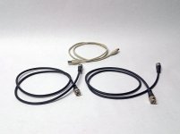
I have all the correct cables. I have one coax connected to the s/pdif out of my USB sound device ---> s/pdif in on the first unit. Then I have a second coax connected to the s/pdif out of the first unit --> s/pdif in on the second unit. I also have the correct USB 2.0 cable for filter configuration.

Many thanks in advance.

Weller Soldering Tips Problem

I recently bought a cheap Weller pencil iron as a spare: model SP40N 40W which uses ST series tips. A terrible product, the LEDs are the old basic clear ones that provide practically no illumination, the iron is no better than a 10 euro iron from the craft shop, maybe worse. I’m having trouble with the tips (original Weller) and after 10 minutes use I've already trashed two. For the first tip I did what I've been doing for 30 years, wipe the tip clean on a damp sponge between uses. For the 2nd tip I used a brass wool ball thing instead. Both times the tip oxidized and got reduced to rough bare metal after 10 minutes and could no longer be tinned. Beats me I’ve never come across anything like it.

Maybe the iron is a bootleg Weller with crap tips but that’s unlikely. I’m using leaded solder and wondering maybe if the current tips can’t handle leaded solder or maybe it’s the flux used in it, solder is tried and true Kester 44. I’m flummoxed and have one tip left before I throw the whole iron in the trash. I always found Weller super reliable and got plenty of mileage out of their tips in the past using their soldering stations.

Maybe someone here has had a similar problem and can say if Weller's gone to crap, or a faulty batch of tips, or the lead solder?

NOOB QWTL concept. Tell me why it won't work and what to simulate it with

So I went and bought the DIY Perks plans for those QWTL speakers he made. I have access to a great 3d printer in work which means I can do insanely long prints like these.

Got most of the way through printing one when I thought, "This doesn't really take advantage of a 3D printer does it"

So here's my concept for a QWTL that would need to be 3D printed I might test with these little tangband woofers.

After the first fold the transmission line is annular. In this model the cross sectional area of the TL is maintained constant with each fold.

Anyway, I'm a noob, so before I spend a bunch on filament to print this thing, it'd be great if someone can tell me why this won't work. Are there particular considerations for annular ports? what do they do to sound?

Also if someone knows what software might be best for simulating a shape like this I'd be much obliged. Could hornresp do a useful job in a case like this?

Screenshot 2023-10-05 at 22.12.13.png

Frankenstein Magnavox CDB582

I posted an AK also....

Bought this today at an estate sale with a bunch of DVD players. Check out all the capacitors added around TDA1541A and about the whole component board. There is a cable soldered in also. The problem is that it won't play music when I connect it to my amps through the RCA outputs.. Tried 2 different tube amps. I can hear what sounds like the CD spinning through the speakers, but no music comes out. The timer counts and it looks like everything is working. I have it plugged directly into the amp, so it should be playing at 100% volume. I don't have a remote. Can't wait to take the cover off the DVD players. 🙂
thumbnail_IMG_2590.jpg
thumbnail_IMG_2591.jpg

Summing wires

I’ve been doing some research into how to convert a stereo signal into a mono signal as I want to connect my decks (stereo rca out) or laptop (trs out) to my amplifier in bridged mode via xlr as this seems to be the easiest connector to hide the resistors. I’ve seen lots of different videos all suggesting seemingly randomised values for resistors, some saying you need to link the unused terminals on the xlr end and some not. Has anyone got any experience making cables like this and would be able to provide more clarity on how to do so

Can you improve these amplifiers?

I am currently trying to design an amplifier for the output of a generator. It needs to work at up to 1MHz, and have a negligible distortion, ideally in the ppm range whilst delivering 30 to 40Vpp.
This is my first tentative:

1687425104742.png

The THD is ~0.01% and there are cheats: spice sources used as ideal buffers, because the base currents of the transistors are too large and too distorted. Additional transistors would be required.
There is also a nasty, unexplained peak in the frequency response, in the region of 200MHz.

Attachments

towards a vanishly low distortion crossover

I am working on an input stage to marry with my latest speaker design (12P80ND + HF10AK).

Here is the input stage thus far.

Simple balanced instrumentation front-end, high-pass filter for subsonic filtering, and a shelving low-pass filter.

The signal chain may be quite long after the buffer downstream to the woofer and the cd.

I'd like to maintain a transparent signal, if at all possible.

Attached v1 of the TinaTi.

1696583318028.png

1696583700889.png 1696583816974.png 1696583777990.png

Attachments

Transtec Transformer TT0869803320-E

Hello,
I am Kathir from India.
I have JBL SCS 140BK230 Digital cinema speaker system.In that My Active sub woofer has stopped.due to No secondary output from transformer and No output details mentioned.It has 5 wires in secondary other Transformer Details Transtec Transformer TT0869803320-E.
Service manual checked No secodary AC volt output data.but in service manual circuit diagram end termination shows only DC details +15V,-15V,0V,+VCC &-VCC.
I have no idea about +VC,-VCC and amp ratings.
Circuit and Transformer derails attached.
It may be thermal fuse or transformer.
If anybody having the replacement or five wires secondary output ,I request pl be post it.

SSE - Choke DCR?

I'm creating my shopping list for magnetics, comparing options and prices. For the choke I have been looking at values in the range of 5-6H with 200-250mA current capability but I have no idea what DCR value is recommended. I searched here but didn't turn up a direct answer.

Should the choke DCR be approximately equal to R1 that it replaces (150R)? Is there a significant effect if DCR is lower or higher than C1?

20N20 availability

Hi there

I'm trying to find out if there is any availability of the Exicon 20N20s anywhere (ideally in Australia.) I heard they are discontinued. If yes, where? Would I only find second-hand ones? Would these be acceptable to use? If not, is there an alternative that would suit my beloved power amp that started smoking a while back? Refer images.

The amp in question is a British made Matrix 1300W amp. I used it for many years and it always hade a great sound, with plenty of grunt.


Or am I best just laying it to rest?

I'm hoping to use the amp to rive some passive subs for my band.

Cheers

Attachments

  • 20N20-1.jpg
    20N20-1.jpg
    298.7 KB · Views: 117
  • 20N20-2.jpg
    20N20-2.jpg
    338.4 KB · Views: 124

Ebay: 500W +/-70V PSU Audio Amp High-power

Hi, I bought this power supply form eBay. I blow it up with a short on the output. I replaced 2 FET transistors blown, and the back 0.1ohm R, but is not enough. Looks like the no-name black module between the caps and transistors is busted too.

404 Not Found

Is molded in epoxy and smashing it I could not figure the schematics.

Would be great appreciated s schematic for such Chinese power supply.

Thank you

Live level active XO sought

Can anyone recommend a an analogue line level crossover with delay for the tweeter and baffle step as well as the crossover? Balanced or not.

Ideally as capable as: https://www.ti.com/lit/ug/tidu035/tidu035.pdf
Additional linkwitz transform capability optional.

Failing that, 'stand alone' PCBs/completed for adjustable baffle step and delay would be OK. There's plenty of choice in raw crossover after all.

What happened to the 'zoom' function in Vituixcad?

On the previous versions of Vituixcad, eg V 2.0.97.1, you could change the scale (zoom in/out) in the graph window by pressing the Ctrl key and then scrolling up or down with the mouse.

The only thing that happens when you do this now is that the size of the graph window changes, but the scale remains the same.

In the manual you can read...
'Picture can be zoomed in/out with Ctrl + mouse wheel'.
However, this doesn't seem to work anymore.

Is the ability to zoom taken away, or am I missing something? Anyone who knows?

Passive Radiator Newbie Q?

I'm thinking about using a passive radiator in a new design rather than a port. I have a lot of experience building ports but never used a PR! One main question - do PRs have unwanted resonances above FS in a similar way ports might have a pipe resonance or let internal cabinet resonances escape? How well do they suppress the unwanted garbage?

I guess it would be important not to excite it where cone resonance kicks in, which would be easy in this case.

crackling aftermarket car speakers

The standard configuration in my car is 2x woofers in the front and 2x woofers in the back. There are also separate tweeters, but it doesn't matter, I won't touch them.
The woofers in the back are blown and in their place I connected BOSE mid-range speakers, which are quite bad to hear (buzzing, crackling... as soon as the volume reaches 45%)

Can I insert only woofers in that place or is there some way to leave these mid range speakers? Im guessing that the car sends low frequencies and they are made for medium. How to solve that?

When I connect the BOSE midrange speakers to my ONKYO mini stereo, everything sounds as it should...

Fosgate 500x bias issue

While waiting for parts in the 600.4 I decided to dig into this.

500x, pc-3084c.

Supposedly no sound on 2 channels but they all work fine. Maybe just the fact that it was in 4 channel mode? Rcas aren’t broke.

Idled at 2amps which seemed high. It only has one pair of output fets per channel. Turned all bias pots ccw. Channel 1 seemed to have a much lower setting then the others.

Channels 2-3-4 adjusted as expected. Channel 1 behaves as some have noted here before… voltage across source stays at zero then suddenly jumps at the pot position you’d expect it to be left at. Idle current jumps 30ma and source res voltage goes to about 3-4mv. Turning ccw causes it to go up to about 7mv before it starts coming back down.

Found this thread. Yep that channel is oscillating even after returning to full ccw and will only stop after resetting remote. No input. Once it starts oscillating and you turn pot ccw frequency drops.

Jumping front/back rca shields doesn’t make difference in oscillating but it does drop idle current about 200ma after reset with pots fully ccw

I want to try the mpsa42/92 Perry suggested first but in case that doesn’t work out …. What are the feedback cap designations for this board to experiment with? I couldn’t find a 3084 schematic and the 3085 board looks different enough that I probably shouldn’t use as a reference

Western Electric New 300B made in USA 2018

Western Electric tubes factory is come back with 300B maybe the other tubes in the future as well let's dream.

Official prices per matched pair was 1299 $ after price update pair cost 1499 $ and single tube was 599 $ today price is 699 $

Probably available December 2018 :clock: in time for its 80th Anniversary.

300B — Western Electric - Maker of electron tubes and high fidelity

Western Electric- YouTube

Western Electric - Official Home Page

Library — Western Electric - Maker of electron tubes and high fidelity

https://static1.squarespace.com/sta...3/000+Vacuum+Tube+Title_Index_Information.pdf

Enjoy :cheerful:

Attachments

  • F50DC0B8-62E0-4EED-A377-5FB06EB5AC32.JPG
    F50DC0B8-62E0-4EED-A377-5FB06EB5AC32.JPG
    162.9 KB · Views: 3,964
  • 604A9D51-D6F6-4BBC-ABB6-3544A7373EE0.JPG
    604A9D51-D6F6-4BBC-ABB6-3544A7373EE0.JPG
    522.5 KB · Views: 3,777
  • 76D6AA5F-A7CD-46A6-A85F-33A42826B29A.JPG
    76D6AA5F-A7CD-46A6-A85F-33A42826B29A.JPG
    348 KB · Views: 3,677
  • 86B44285-8585-4598-B346-AD824DFBA29E.JPG
    86B44285-8585-4598-B346-AD824DFBA29E.JPG
    289.6 KB · Views: 3,576

Installing LinearX LEAP 5 on 64-bit Windows 7 / Windows 10

With Chris Strahm's passing, there seems little hope that LEAP will be upgraded to support 64-bit platforms.

I have LEAP working on 64-bit Windows 10 -- dongle driver installed, software install errors worked around, etc. (It's far less complicated than on 64-bit Windows 7.) I've written up instructions and need a few folk to help test before I share the instructions more widely.

If you have LEAP and 64-bit Windows 10 and are willing to test the instructions, please send me a PM stating your version of Windows 10. (If you're interested but not willing to test, please post a message of encouragement.)

Thanks.

JL Sounds I2SoverUSB viii locked to 48khz sample

Hey folks, I am running a JL Sounds I2SoverUSB vii into an AD1862 configured like the JL manual instructs. This works fine with standard Windows 11 drivers and with the supplied JL Sounds drivers available on their site.

With either Windows 11 drivers or JL Sounds drivers, the unit is locked into either 44.1 or 48khz sample rate. When I am playing 96khz files, it downsamples to 48khz.

Does anyone know why this is? I can't find any option in the JL Sounds driver software to change this. I'm a little confused, what should I be looking at?

Luxman L308 refurb: technical questions for main amps.

Hi all,

Refurbishing an old defective Luxman 308 amp, I found the main amp boards schematic is like the following (of the l80) and although there may be more, my first questions are:

1. why is the r115 resistor supplying the zener so low (zener gets some 15 milliamps as supply voltage is around 45 and it will run quite warm, as does the resistor). Note, in a newer amp (l85v) they do not not have the r116 470 Ohm but the 1k5 resistor is 8k2 there.....

2. Just drilling 2 little holes, I can bypass the zener with a little cap, would this be beneficial? read: will zener noise affect operation much, here?
Luxman did this in a later mode L85v having same input circuit (although the mentioned 5k6 resistor is 4k7 there)l, they put in a 40 nf ceramic cap.
I presume they just standardized on 40nf caps, as they used this value as ceramic bypass on several positions in different amps. I could put in a nF range ceramic cap, there is not much space for anything else, or a little tantalum electrolytic of a few microfarads, which could fit.


308schema.jpg

B1K Preamp

First off, this is not either of the two units that I was working on as described in the B1K thread. I actually had nothing but success with this one. I really like building these and going with different, sometimes the same look as the one before it. No headphone output here FIY.

Anyway, I built this with yet another 554 cigar box. It does look sweet, Made an oversized power supply for it with good filtering designed by Pete Millett. Mostly, the things that I added are cosmetic, but also it is a heavier unit with the thought vibration control behind it. Note the Pete Millett isolation mount for it. Also, I will point out that there are 2 inputs, each with a different level so as to have more control of source input. One input is about 12db down from the other. Questions welcomed.
$400+ shipping.

Attachments

  • P7270001.JPG
    P7270001.JPG
    468.7 KB · Views: 174
  • P7240012.JPG
    P7240012.JPG
    292.5 KB · Views: 172
  • P7240005.JPG
    P7240005.JPG
    436.1 KB · Views: 171
  • P7240002.JPG
    P7240002.JPG
    755.4 KB · Views: 170
  • P7240008.JPG
    P7240008.JPG
    441.4 KB · Views: 167

For Sale Quant Asylum QA400 Audio Analyser

Due to upgrade the QA400 is now surplus to requirement.

Purchased new the QA400 has served me well and is a good reliable piece of kit and is in top condition.

The loopback test results screen capture are in the last image below.

The QA400 USB front end control software runs directly under Windows XP, Vista and Windows 7.

Windows 10 and 11 require the use of eg. the freeware VMWare Workstation Player to run the QA400 control software, same applies to running the QA400 under Linux.

The QA400 comes in the original box with the original set of loopback BNC-BNC leads, a USB cable and a printed copy of the user manual. The latest Windows drivers will be available for download from my dropbox.

The comprehensive user manual, which details the QA400 large range of test functions and example test scenarios, can be downloaded from here...
https://drive.google.com/file/d/1pfUUaTyY7UthGmwvAENqAqeGdrtr3tyg/view?usp=sharing

Price is £175 including insured shipping in the UK, though sensible offers will be considered, payment via Paypal.

From a pet free and non-smoking household.

QA400 6x4 1.jpg

QA400 6x4 2.jpg


QA400 6x4 3.jpg


QA400 6x4 4.jpg


QA400 6x4 5.jpg


QA400 6x4 6.jpg


QA400 loop back test large.jpg

Attachments

  • QA400 6x4 5.jpg
    QA400 6x4 5.jpg
    519.4 KB · Views: 112
  • QA400 6x4 6.jpg
    QA400 6x4 6.jpg
    519.2 KB · Views: 104

JLH Class A Hart Kit construction thread 1996

Hello folks

Yes yes I know I have many construction threads, but this little project has been on the back burner for some time, while I am waiting for parts for my many other projects I thought I would have ago at making one of these units and see what all the fuss is about. I have a big batch of original Hart (William hart kits) PCB's so will make a stock unit to make sure all works and improve if I can with all the knowledge on this site ... wish me luck, but at least a lot cheaper then my valve amps that I make

forgot to mention this is a Class A mono block power amplifier ... approximately 15w full class A

RF T2500-1BD going into protect with speaker load

Hello

I'm working on a t2500-1bd (not the constant power version). This amp had 2 bad output FETs and a bad PNP at the gate that pulls down the drive signal. After replacing them with used, but good parts (to test) the amp powers up and plays music fine. The issue comes when I turn the volume up with a speaker connected. The amp will seemingly turn off with a brief second and come back on, before the amp turns off it is drawing about 10amps of power, sometimes it is a little bit more/less. When this happens, I see the protect light come on and then turn off when the amp comes back on. I've tried 1ohm and 2ohm speaker configurations with same results.

If I remove the speaker and run the amp with no load, I can drive the amp into clipping (about 200 volts peak-peak) without any issues. The HV rail test point is reading about 108-110V at idle. With a speaker connected and playing music, it will drop to around 93V before the amp turns off.

The +/-25V rails (RF schematic calls it +LV_CLEAN and -LV_CLEAN), looks stable before the amp turns off as well. Gate drive to power supply FETs look normal until the amp turns off.

DC offset is <50mV

DC voltage at the power input terminals when the amp turns off is no less than 13.20V.

Playing a 40Hz tone with a speaker attached and my oscilloscope looking at the output of the amp. The sine wave looks nice and clean up to the point it turns off.

I think the issue is on the BD power supply card. Maybe some noise is getting onto the protection circuit when high current is present? Anyone have the schematic for the BD PS card? Or potentially know any specific components to check?

I also noticed I sometimes get a slight hum at the speaker with RCAs connected to the amp with no audio playing. Sometimes it goes away.

RPi+DAC+Hypex amps in one case. Who has done this?

I’m researching active crossovers for a possible future build. What I’m looking for is,
  • Raspberry Pi
  • Six+ channel DAC
  • 6x200w amps
All in one case, around the size of an AVR.

It seems doable, but my searching hasn’t provided anything. I’m just looking for ideas on cases, layout, and positioning of components. Trying to fit three Hypex amps and two power supplies while providing enough space for cooling and separation for the DSP seems tricky without getting a large case. Maybe I should befriend some engineers from Denon 😆

edit
I found this earlier in the week which got me looking for similar designs with more powerful amps.
1695421218285.jpeg


https://www.audiosciencereview.com/...to-the-smartcross-project.47976/#post-1721601

First time speaker building - need help with REW + Thiele small signal

I'm working on building a set of bookshelf speakers. I bought two 7" RS180-8 speakers, and just finished setting up REW to measure them. I built the impedence rig myself, and it seemed to work fine.

The one issue (maybe?) is that my parameters are quite a bit off from the published specs. I tested both speakers, and both are similar. But here are some rough deviations:

Left Speaker
Vas 14.85 litres
fs 49.4 Hz
Qts 0.464

Right Speaker
Vas 17.81 litres
fs 45.9 Hz
Qts 0.424

Published:
Vas 24.4 litres
Fs 35.7 Hz
Qts 0.31

Is it normal for the real measured parameters to be so far off? Anything I should look at adjusting?

My resistor measured 98.7 ohms, and I added about 70g of mass to the cone (which might be too much).
The drivers were fresh out of the boxes.
I'm using a USB Scarlet 6i6 sound interface.

Thanks.

Really small enclosure for Peerless

I recently purchased a pair of Peerless PLS-P830985 with which I wanted to make very small speakers for the computer workstation.
I had seen a fairly famous design in Japan:
https://item.rakuten.co.jp/nfjapan/h217/
No information can be found on a possible diy construction on your own, I tried to extrapolate some information but wondered if anyone here has already tried their hand at such a project.

PS Audio phono pre

Hi,
I would need some help please.
About 35 years ago I built a PS Audio phono pre, in which the RIAA-correction was made with a passive network between the input and output stages. That's all what I know of it after such a long time and now I'm searching for the circuit diagram.
Maybe someone could help, it would be much appreciated.
Many thanks in advance.

Beveridge III: suitable replacement woofers?

Hello everyone.

A friend of mine owns a pair of Beveridge Model IIIs. He renovated the speakers quite extensively, remade the cardboard bezel, and they work well for the electrostatic part. The woofers, however, were in poor condition, and he had to replace them. He chose - because he did not want to spend too much money without knowing exactly which speakers to replace the originals with - speakers of much lower quality (4 x 10" SKYTRONIC Model 902.214 woofers whose specifications appear below). I picked the T/S parameters for the Skytronics and made a comparison with Dynaudio 24W75 which could be candidates for replacement, see attached file.

Now he would like to replace the Skytronics (equivalent Fenton speakers), because the bass is not as dry, tight and fast as the electrostatic membranes, naturally...

At his request, I made him an active filter kit from Rod Elliott, a Linkwitz-Riley with a slope of 24dB/octave, cutoff at 200Hz as it was originally. The bass channel is driven with a Hafler 220 amp and the ESL is driven by a Luxman tube amp (a kind of Luxman MQ-88uC).

The volume of each bass speaker is approximately 65 liters. For those who are not familiar with the Beveridge model III, each speaker has 2 woofers, one at the bottom which radiates downwards, the other at the top which diffuses towards the ceiling. The enclosure is bulky, high (more than 2m) and wide (a cylinder approximately 60cm in diameter).

IMG_6184.jpg
IMG_6183.jpg


As you could expect from an ESL, the mid-high is splendid. By comparison, the bass provided by current speakers is a bit slow and boomy. The speaker load is closed, and occupies a volume of approximately 65 liters per speaker.

I'm not an expert on speaker load calculations.

I would like to know how to proceed with this replacement, if someone has good ideas or experience?
  • find the exact equivalent
  • find a speaker that respects the characteristics of the original speakers
  • find nearby speakers, even if it means modifying the cutoff frequency
  • the idea is not to remove this bass from the speakers to replace it with an independent subwoofer (solution sometimes recommended)

I'm listening to you !
thank you so much.

Skytronic T/S parameters as I could find them (and Dynaudio 24W75):

T:S parameters.png

Baffledesign with Guides

Hi all,
one question i always asked to myself, what pros and cons are those waveguides at midrange, bass driver in some designs.

magico1-2.jpg


ok, this is a real expensive speaker (something for the eyes ; ) , but i saw this at cheap shoutboxes also.
so, benefits more directivity in front of the speaker ? and still using a rounded baffle ?
only for looking fancy ? makes sense ? better for positioning at wall ?

we all try to flush mount our drivers to avoid diffraction, this is looking to me as it would create diffraction. or do they not ?

help me to understand this 😉

The effect of port volume of reproduction quality

This isn't a question about velocity.
I've noticed that speakers with larger port volumes produce more woolly, loose bass when compared to their counterparts.
e.g. a cabinet tuned to 50hz using a 50mm port sounds better than one tuned to the same frequency using a 75mm port.
How does the volume of resonator affect performance?

nb: The port frequency remains the same regardless of diameter, length is adjusted to maintain frequency.

Are these original ones?

I am inquiring about the authenticity of the MJE350 components in question. While I am aware that they do not originate from "ON," I am curious about their reliability. Typically, I tend to steer clear of Chinese-made components as they often exhibit characteristics of imitation from afar. However, I've noticed that this particular store boasts 51 reviews, all of which praise the quality of these components. This situation has piqued my suspicion, as it seems somewhat anomalous.

1696277155234.png

832A Three Years On

I built this amplifier 3 years ago, initially with a 9002 front end, AC coupled to a 6C4 cathodyne PI. Eventually modified to a triode strapped pentode front end, fixed bias 6C4 cathodyne, and now, a pentode front end DC coupled to the 6C4 cathodyne. I developed (f**cked around but wrote things down) the first stage using the 5654/6AK5 tube, which worked well with a B+ of around 100V. -4dB of GNFB. The amp measured 0.3% THD+N at 2.83V, 1kHz, but things start to go down hill fast after that. Fortunately, 99.99% of my listening is done at a level less than that. Output is about 7W RMS. With the previous triode strapped pentode topology, I was able to swap in a whole host of different tube for funsies. I didn't think I would be able to do so with a pentode front end, but just for giggles, I tried. Surprise, surprise, all the different tubes I tried worked (6AJ5, 6BH6, 6186W, 6AU6, 6CB6A, 6DE5, 6DK6). There was no weirdness on the oscilloscope, though I didn't bother to measure each different tube. I just noticed that the gain was different, but not by much. Interesting thing is that when I first breadboarded the pentode front end, I tried the 6AU6 first, and it did not like the low voltage. The sine wave on the oscilloscope looked all weird and asymmetrical. I guess the negative feedback calmed things down quite a bit.


Amp.jpg


832A.jpg


Overall.jpg


Schematic.jpg

For Sale IanCanada PCBs - I2S, FifoIIv6, Dual XO clock + interconnects

I have partially dismantled my dual balanced TDA1541 DAC and have the following IanCanada boards for sale as a set.

I2S to PCM, FIFO II V6 , Dual XO clock board with 45 & 49MHz XOs, plus interconnects. All working and have been for a few years.

Together they offer two front panel switchable I2S inputs eg for USB and SPDIF inputs (via suitable interfaces), and support most of the old school DACs in single or balanced modes – see list below.

All the required interconnecting cables are supplied. Fifo inputs are via U.fl connectors or PH2mm pcb connector and the datasheets can be emailed to the buyer for the Fifo II and I2S – PCM boards. None needed for the XO clock board. ALSO INCLUDES 3, U.fl to panel mounting SME female cables.

I2S BOARD SPECS:

1. Support 16,18,20,24 bit PCM format output
2. Accept 16 to 32bit I2S input signals with SCK from 32*Fs to 64*Fs
3. Pure NOS mode with bit-perfect format converting
4. High speed design capable for 384KHz Fs with maximum MCLK up to 100MHz
5. Support PCM63,AD1865,AD1862,PCM1704,PCM1702,TDA1541/A and many other classical MULTIBIT DACs
6. Support TDA1541/A working at offset binary mode
7. Jumper selectable full-speed mode and half-speed mode
8. L,R simultaneous timing, launching D/A conversion at same latching edge to eliminate L/R phase difference
9. In order to reduce DAC noise floor, bit clock can be stopped after data shifted into DAC (default)
10. Delayed falling edge of latch enable signal (LLLR) applied to stop clock mode
11. Support dual mono DAC configuration
12. Jitter optimized synchronize logic architecture with last stage high speed low noise re-clocking flip-flops driven by original MCLK

FIFO II V6 SPECS

Two I2S inputs.
LVTTL (3.3V) logic input level with 5V TTL tolerant The two inputs are by U.fl connectors.
Fs range - 44.1 KHz, 48 KHz, 88.2 KHz, 96 KHz, 176.4 KHz, 192 KHz, 352.8KHz, 384KHz - 16bit, 24bit or 32bit.

I2S input ports can be selected by a jumper or a on/off switch on front panel

Switching between two I2S sources is a glitch-free design. At the moment of switching, FIFO II output will keep streaming with no stops on any of the clock signals, such as MCLK, SCK/BCK and WS/LR, but SD/DATA will become zero to keep digital silence until new I2S signal is locked.

I2S output - LVTTL (3.3V) logic output level, compatible with the Xo clock and I2s to pcm boards.
44.1 KHz, 48 KHz, 88.2 KHz, 96 KHz, 176.4 KHz, 192 KHz, 352.8KHz, 384KHz - 16bit, 24bit or 32bit.
FIFO Memory - 4Mb SRAM. Speed 10ns.

DUAL XO CLOCK BOARD

The XO clock board just plugs between the Fifo II and I2S boards and also supplies the MCK to the I2S board via a U.fl cable. (included)

Multi-frequency MCLK output capability
  • Automatic switching of the MCLK and Fs depending on the input I2S stream from 44.1KHz to 384KHz
  • MCLK x Fs range: 128*Fs, 256*Fs,512*Fs,1024*Fs,2048*Fs
  • I2S re-clocking input: LVTTL (3.3V) input level
  • I2S re-clocking outputs: Two independent groups, natively support DAC in dual mono configuration
With LVTTL (3.3V) logic output level and maximal re-clocking frequency of 600 MHz
  • Power supply: open to external low-noise power supplies or battery
  • Enhanced EMI filters and bypassing/decoupling networks
  • New anti-vibration grommet solution
  • Reserved for three point three support
  • Stacking possibility

All three with cables etc cost over $300 a few years ago, selling for ~£130. (~$150) + insured shipping – about £20 mainland EU, £30 Australia/US/Canada but will be confirmed.

Please PM me if interested.
3PCBS.jpgFIFOII.jpgXOPCB.jpgI2S.jpgCABLES.jpg

How does 2-stage loudness work?

I found the vintage Grundig amplifiers have 5 tabs volume and I also acknowledged that that part is used for 2-stage loudness function. For a conventional 4 tabs volume, the loudness will proportionally vary with the volume level, or turning angle. I wonder how does the 5 tabs pot or the 2-stage loudness work? Is it equivalent to having 2 styles of equalization settings? I mean it won’t vary resistance with the turning angle, but have only two levels of bass/treble boosting? Do I understand correctly?

Thermally stable zener voltage references

Hi All,

The first pic shows the Vishay 500mW Zener Diode datasheet. The second shows the same table with the tempco converted to V/degC.

There seems to be a generally accepted notion that Zener diodes in the 5-6v range (highlighted in red) are the most thermally stable. I have read this on countless reputable websites and assumed it as fact for a long time. Where does this come from? Unless I do not understand the attached datasheet properly (highly likely), it would seem these have a pretty reasonable positive tempco. The only thing I can think of is that this has been derived when using them in some kind of BJT voltage regulator, where they will in fact neatly cancel the -2mV/degC Vbe tempco of the BJT.

However, it seems to me that the 3.9V and 4.3V Zeners (1N5228 & 1N5229 - highlighted in yellow) have a near equal but opposite tempco. If one wanted a very stable voltage reference, the best thing to do might be to run an alternating string of these in series. This of course assumes each device is kept at the same temperature, an issue that applies to any multicomponent voltage reference.

Any thoughs?

Cheers,

Greg

1696656415271.png


1696656697929.png

BBE MAxcom and a Godfather

I am forced to use a BBE maxcom in a club (by a 70 year old Godfather of clubs) as a main limiter in the system .
Godfather owns from previous operations top notch systems like loads of Renkus Heinz units , loads of P series EV amps and loads of any Rane you can imagine 2*32 EQ's/ 2*16EQ's loads of 3way 2 way xovers .
Top notch equipment but OLD ....Old but properly serviced
checked a few x overs all fresh top quality capacitors , all pots and switches superb clean all according to specs
Checked a couple of EV amplifiers mint clean , new top quality vents , all settings made very precise like limiters and bias and so on , some also with fresh caps ....
So in a 70 year club Godfather there is not much to do to change his opinion about something .
His opinion is that : Go behind pick up any of the equipment you like that i allready payed to get, and payed to service properly, set my new club, but keep in mind that i am not giving a single dollar for new equipment .
I explain to him that when you have a club that have a huge dance floor system and 2 other systems to cover the rest of the areas, there is no way that you get way with it without time alignment ....There is going to be areas of the club that sound is going to be messy .
God father said : how you did in the past without all these digital thingys
I said we did our best but this doesn't mean that we managed a 100% result at least regarding these details phase and time alingments
very well he said .....Just do it one more time..... period
Configuration is Allen Heath mixer goes to maxcom then to three systems that are 2*32 RAne EQ 3 Way Rane Xovers and then EV P series amps to Renkus Heinz Speakers .
--------------
been operationg loads of DBX , had to study DCX 2496 to tackle arround many details to make it sound properly and managed .Actually i will say if compresosrs and limiters are set correctly the DCX 2496 is better in safety than any drive rack from DBX .
Configuration though like above i haven't done since the 90's and BBE maxcom is the first time in my life
I am totally socked from the performance of this machine ....had to remove from the system 5 times to see what the diference is
Sound is very dynamic in moderate levels and you dont have to push the system close to 100% to get nice sound impact and dynamics
it appears that maxcom with the sonic maximizer active interacts with the music program adds and remove things to acheive the target
Sound is very very clean and very dynamic .
Its socking good even if the limiters kick in
Is there anyone that used this machine in a similar way ?
is there any more information about this application ?

Thank you
  • Like
Reactions: indianajo

For Sale: Type 26 preamp by Andy Evans

For sale: Type 26 preamp built by Andy Evans. The unit has filament bias with Lundahl LL1692 output transformer. The preamp is in good working order with no hum on low gain amps like my korneff 45. But hums on high gain amps… Asking$200.00.

3C5FDAD1-D9FE-4A05-81AE-EE91FC01523A.jpeg

Thanks for looking.

82EB9ED5-5D5B-432A-88B5-279461CA09F6.jpeg

Attachments

  • A19E4CDA-F214-455D-994B-1B1E75D942F7.jpeg
    A19E4CDA-F214-455D-994B-1B1E75D942F7.jpeg
    433.3 KB · Views: 408
  • 028BE373-A5FB-4EBC-80C7-371D0969346F.jpeg
    028BE373-A5FB-4EBC-80C7-371D0969346F.jpeg
    415.1 KB · Views: 402
  • B6B1C152-8FE6-488A-BE0A-DC71F269959E.jpeg
    B6B1C152-8FE6-488A-BE0A-DC71F269959E.jpeg
    438.2 KB · Views: 383
  • 8A3F1A05-2634-4C42-BC68-0FE4B608714D.jpeg
    8A3F1A05-2634-4C42-BC68-0FE4B608714D.jpeg
    403.8 KB · Views: 421
  • Like
Reactions: naca5

Balanced DAC to Unbalanced Preamp

I currently have Muzishare X7 and want to add a Okto dac8. Muzishare only excepts unballanced rca signal and Okto only outputs balance signal. Contacting Okto...they said to use a Lundahl audio transformer LL1584-3FXPHM. Link included. I am looking for opinions on whether the transformer will degrade the signal and/or sound? Okto hasnt given me a clear answer. Contacted Lundahl and they said it wouldn't degrade the signal/sound but may enhance it. When they said enhance it...it made me think...how can that be...if the dac is sending a clean/pure signal...I dont want it enhanced/changed. I am new here but figured there are people on this forum that may be better at answering my question than anybody else.

https://www.lundahltransformers.com/wp-content/uploads/datasheets/1584_x.pdf
https://www.lundahltransformers.com/product-highlight-ll1584-problem-solvers/

Thanks for any input

Output stage is not complementary?

Hi, I was very lucky to find a deal on an New-Old-Stock sealed in original box "Samson Servo 170" studio amplifier, also before purchase I was considering either an ART SLA-1 or a Samson Servo 120a(the latest Servo versions) but the internal quality/parts of those amplifiers where questionable to me, however looks like the last production/batch of this early/old Servo 170 amplifier didn't used complementary output stages due the transistor obsolesce/shortage and I'm worried about sound quality and stability issues.:scratch2:

This amplifier will be used only for tweeter duty only and I probably shouldn't be worrying at all but I want suggestions if a VAS upgrade is worthy or not, here below are the amplifier output stage info and my VAS upgrade considerations:

Servo 170 originals(Obsolete):
2SB688 (Ib: 1A, Ic: 10A, 10MHz) <--- OK
2SD718 (Ib: 1A, Ic: 10A, 12MHz) <--- OK

Last Servo productions?(Obsolete):
2SB688A (Ib: 1A, Ic: 10A, 10MHz) <--- OK
2SC5197 (Ib: 0.8A Ic: 8A 30MHz ) <--- ???

Replacements(I'm considering this ones):
2SA1943N
2SC5200N

Replacements(They has high output capacitance):
NJW3281G
NJW1302G

Regards!

A quagmire of bass proportions? 300 watt sweep tube amp questions

Hello everyone, just getting some opinions. I’ve had an idea in my head for a while that everyone seems to think I’m crazy for, I’m looking to build(or likely have built; this may be out of my experience range) what I consider the ideal gigging tube bass amp. Power is 300w, ideally clean. I know that the Svt is the go to for this sort of thing but both of mine have been unreliable tube eating behemoths. Having had mine apart so many times they’re quite complex pieces of design, and I may be of the persuasion that they could be simpler.

My sketch out was to use Svt transformers as they can be acquired used for reasonable money, anything else is probably $800 or more in just iron and I think they’ll do what I need. That gives me ~670 vdc loaded and around 1900 ohms for a plate load if I remember right. I’m unsure of tubes, but I have considered a quad or sextet of 6kg6s, 6lw6s, or 6146s. If I have to kill lots of tubes in the process I’d rather it not be $100 6550s. There have been posts of many successful builds with sweep tubes but I have absolutely no experience with them so I’m open to advice.

The abject goal here isn’t cost, though like most of you I’m sure, I’d like to keep it reasonable. My main goal is reliability and simplicity or as close as I can get. I hate having to undo 10 plugs, many pots and jacks, and remove two boards any time I have to do something.

Essentially, if presented the above design criteria, what would y’all do? I’m still a puppy in tube electronics, and I’m sure there are fellas on here that have done this longer than I’ve been alive. I’d love to hear suggestions.

Before someone says try solid state, I have and it didn’t last one gig without fire and fixing that one almost took an act of Congress to get parts, so I’d like to stay tube if possible.

6N8S (6H8S) Output stage for DAC

Hello,
I made a DAC with a 6N8S tube output and I don't know why there is such a drop at lower frequencies? The power supply is 114-0-114 VAC through the EZ81 tube and the filter is CLC: EZ81-C30uF-L16H/480ohm-C100uF. Ra=7k5, Ua=120V, Ug=-4.6V, Rk=1K, Ia=4.6mA.
The DAC is ES9018 (voltage output 1Vrms=3Vpp) and input to the grid is via a 4uF capacitor. Without grid stopper. Output capacitor is 1uF, connected to 100K pot. I am attaching the freq. characteristic.
Does anyone have an idea why there is such a drop on low freq. (100Hz=-1dB, 50Hz=-3dB, 20Hz=-7dB)?

Thank you.

6n8s.jpg

Linearizing the CFP crossover - P3a of Rod Elliot as example

The problem with CFP outputs is the double cut off of the two transistors separately. As the driver needs to bias the output, it needs extra current, hence switches off later linearizing the crossover current. To get a perfect crossover the currents must increase with square law. To get back square law, I simply added a biasing current to the output so that the drivers don't need the extra linearizing current.
Bellow shows the difference of P3a after Sakis @East electronic and my version.
cross over d.JPG

The third curve is the output voltage of the amplifier while a triangular current generator pouring +/-2A.
P3a mje.JPG

Attachments

  • sakis.JPG
    sakis.JPG
    107.2 KB · Views: 304
  • RE P3bmje.asc
    RE P3bmje.asc
    5.3 KB · Views: 140

Help understanding portion of schematic and swapping tubes in circuit...

I've got all the parts for a more or less Loftin White 2A3 build, but I realize I'm not totally clear on how a portion of the circuit works—specifically the area I've circled in red. I've been familiarizing myself with a variety of Loftin White-inspired circuits and most of them seem to have a hum pot on and cathode resistor and cap on the 2A3. This one does not and would love some insight into what is happening in this section. Perhaps it's obvious, but it's all new to me. Wanted to start with a simple circuit as my first ground up from schematic build.

After some poking around online, I've found that a 6SQ7 is a suitable replacement for the 2A6 (different heater and base). That said, I've got a couple of 6SL7 tubes on hand and would like to save some money. As far as I can tell, the circuit is only using the triode portion of the 6SQ7 and my question is can I use a 6SL7 instead (only one triode section)? They seem pretty close in spec however the amplification factor is different as well as more plate current draw and higher transconductance. As long as my power supply can handle the extra current draw how will the amplification factor play out downstream?

Thanks in advance!

Screen Shot 2023-10-04 at 10.15.23 AM.png

Attachments

Picking an amplifier

Hi all, I’m doing a project with a soundboard, where I will hit a button and a horn sound will be produced through a loudspeaker. I am going to be using an 11ohm siren speaker. I’ve tried using Amazon amplifier boards and the amp that came with the siren, but most siren boards cannot play other sounds without heavy distortion. I can’t find any mono amps on amazon that are either full range or actually the advertised output. Looking for at least 200watts rms. Thanks for your suggestions!

Mixing types of parallel cathode bypass capacitors

I've found a lot of great information on bypass capacitors in regards to the type that people prefer and the potential benefits and disadvantages of paralleling capacitors. My question stems from what I have on hand in my parts bin...

I need a 220uF cathode bypass cap on a 12AT7. I dont have have a 220uF cap on hand BUT I do have a variety of caps that will get me there. Specifially, a 100uF tantalum capacitor, a 100uF electrolytic and a 100uF film cap - plus some smaller caps to get me to 220uF. What are people's thoughts on paralleling different types of capacitors in this application?

For example, what are the potential advantages and disadvantages of paralleling a 100uF tantalum, a 100uF film and a 20uF film?

Of course I can go buy a cheap electorlytic and call it day, but I'm here to learn.

Markaudio CHP90 WAW - request advice

Inspired by Curt Campbell's Halcyon design, I'm starting to do my own take on a WAW.

Main FR driver I'm starting with is the Markaudio CHP-90.

I'm currently considering two woofers to pair it with:

The paper version of the Dayton Audio RS225

or

The Satori MW19P

Ideas on configurations would be 2x4ohm in series or 2x8ohms in parallel as either a TMM or MTM.

Working thru modeling in Speaker Sim to get a grasp of how the combinations would play together sensitivity-wise and some preliminary x-over slopes/points. The RS225P will be limited on bass output with the usual sealed or ported cabinets. Haven't investigated a TL as I'm new to designing for them. The MW19P has quite a disparate price tag, might be other options that are cheaper.

Anyone got some ideas/advice/suggestions/input to go off and consider?

-tom

ACA Power issues

HI Folks.
I finally decided to dip my toes into building an ACA mini amp,
I assembled the PC and believe all the components are installed properly. not the best looking solder joints but they seem to be OK, however I can't seem to get it to power up.
I tested the power supply and it does test at the proper voltage. 23.88vdc.
The power light blinks slightly every 4 seconds but doesn't stay on.
Also, when I plug the power supply in, an arc jumps from the outer barrel on the plug to the outer wall of the input jack.

Can anyone point me in the right direction to trouble shoot the issue.

Thanks in advance.
Richard

LM1875 distortion... any alternatives?

I was looking at the LM1875 to make an amp with about 5W max output and minimal component count. It looked fine until I saw the distortion graph.

The quoted distortion looks great with "0.015% at 1kHz and 20W". Problem is that in a living room and normal speakers, you very rarely use 20W. So if you look at the graph, then distortion is more 0.07% around 1W. Which is about 10 times more then the LM3886. And that hump is really strange compared to almost any other amp, chip or discrete.

Any better solutions? I'm looking at a minimal components amp that can do around 5W bearing in mind that in the end I might need 24 or more of them.

Altec 1202a, different CDs?

Looking at buying a pair of 1202a speakers with 422 woofers (kinda like a 418B) and 807 CD’s on 811 horns. The two 807 drivers are different, one black an the other green. They are not quite the same, one is an 807-8A, the other 807Z and the witing terminals on the latter look ‘strange’. Makes me wonder what I’d be getting - Thoughts ?

Idea is to eventually re-use for mini Vott.

Attachments

  • IMG_7020.jpeg
    IMG_7020.jpeg
    42.3 KB · Views: 79
  • IMG_4980.jpeg
    IMG_4980.jpeg
    318.3 KB · Views: 88
  • IMG_7019.jpeg
    IMG_7019.jpeg
    59.2 KB · Views: 69

Can someone help identify what circuit was removed in the MkII version of the ARC SP10 preamp?

I recently acquired an Audio Research SP-10 preamp, specifically the well regarded Mk2 version. I immediately noticed a large bare area in the middle of the main circuit board, that clearly was populated in the prior revision. Attached are pictures of the Mk1 and Mk2 boards, as well as the schematics. I'm trying to work out the purpose of the removed circuit. I'm used to ripping out large seconds of code when optimizing software projects, but I've never seen it in a circuit design before!

Attachments

  • ARC_SP10_top-1.jpg
    ARC_SP10_top-1.jpg
    87.8 KB · Views: 142
  • ARC_SP10MKII_top-1.jpg
    ARC_SP10MKII_top-1.jpg
    79.3 KB · Views: 144
  • ARC_SP10_manual_schematic.pdf
    ARC_SP10_manual_schematic.pdf
    5.3 MB · Views: 169
Projects by fanatics, for fanatics
Get answers and advice for everyone wanting to learn the art of audio.
Join the Community
507,630
Members
7,880,913
Messages

Filter

Forum Statistics

Threads
405,900
Messages
7,880,913
Members
507,630
Latest member
bassahaulic