I would like to minimise the number of power chords going to the rack and service everything through one main cable.
Interested in safety issues or earthing issues, noise issues with the below proposed wiring :
Thanks!

Interested in safety issues or earthing issues, noise issues with the below proposed wiring :
Thanks!
Powercon is a good choice, Speakon can also handle 30-40A depending upon application.

Should work fine if you use PowerCons (as they are the ones rated for mains duty). There are even versions with a built-in "loop" connection as you show here you want.
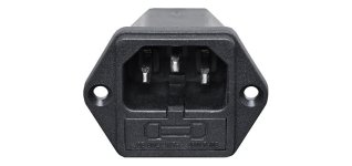
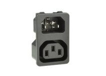
A female IEC chassis jack and a male IEC chassis jack on each chassis for AC in and out, and a cable with female and male IEC connector for chassis to chassis connection would work.
Attachments

Think about what can go wrong and make sure there are fuses to cover all possibilities.
Erm, power chords are something else 🙂, but for power cords I'd be a bit wary about daisy-chaining too much - better to have a power distribution box with separate leads to each block - each appropriately fused. With daisy chaining you might have a fault in one unit taking out a different one purely because they shared a fuse or power lead, and selecting fuse ratings becomes a compromise if a unit might or might not be powering others as well.
Also the more leads in a chain the less effective is the earth bonding as more and more contact resistances and cable resistances are added. How might you PAT test the setup for instance?
Also the more leads in a chain the less effective is the earth bonding as more and more contact resistances and cable resistances are added. How might you PAT test the setup for instance?
In the UK one outlet can manage 13 amps so your system would be limited by that.
With 2 separate mains leads you can take 26 amps from the 30 amp ring main.
With 2 separate mains leads you can take 26 amps from the 30 amp ring main.
Yes! Thinking about it, I will probably go with an IEC inlet with included fuse & switch for each monoblock to remain safe and simple.
I would love to use powercon, but the only incentive is the standard cutout in the chassis, and it's not really worth the bother of adding a custom switch, an external fuse, and a custom cable!
I would love to use powercon, but the only incentive is the standard cutout in the chassis, and it's not really worth the bother of adding a custom switch, an external fuse, and a custom cable!
13 Amps at 230/240 Volts will be more than enough power for any home hi-fi system.In the UK one outlet can manage 13 amps so your system would be limited by that.
With 2 separate mains leads you can take 26 amps from the 30 amp ring main.
in France, regular outlets are 16A, with 20A and 32A available but usually found in the kitchen and not in other domestic parts of the flat/house.In the UK one outlet can manage 13 amps so your system would be limited by that.
With 2 separate mains leads you can take 26 amps from the 30 amp ring main.
The proposal in the first post is decent; powercons are very high quality and highly reliable mains-voltage connectors. I've used the TRUE1 variant quite a lot for mains-power applications. Some of their reliability is due to the quality of the contacts, but also because they lock into the socket; moving equipment around or pushing it into shelving doesn't easily cause dodgy contacts. In my view these are the premium and best choice if the cost is acceptable.
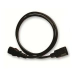
IEC C13/C14 connectors are cheaper, but should still be fine for normal HiFi amplifiers (ignoring cheap unbranded types that may not comply; go for a decent brand). They are also a lot more common, for compatibility or finding a spare/replacement lead easily.
Though with cheaper non locking connectors (or higher power applications), I would personally prefer parallel power connections for each device, rather than series/chained connections. In a chain, any issue with one connector affects everything else downstream of it. You can get (or make) IEC power distribution units (PDU), for example. I also have some leads with a wall plug on one end that is split into two IEC line-sockets on the other end.
There's this thing called a power bar. Buy a good one. Then use short power cords to connect the equipment to the power bar. At Mouser/Digikey/others you can get power cords down to 30 cm in length. That'll make for a nice and tight installation.

Tom
Tom
Yes, though the OP's location is given as France, so probably not that exact one. 230Volt European sockets would work, but the IEC format would be more compact, and of course (at a price) such things exist or can be made also for powercons. These things can be called bars if in a row, or multi-way extension leads in consumer circles, but they're all the 'power distribution units' I referred to.
Though if the requirement is less extensive or modular, maybe look up something like 'split IEC lead' . For example, things like this
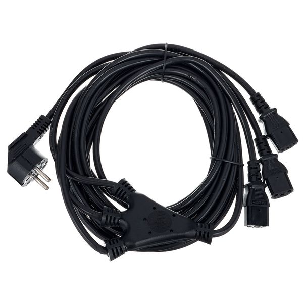
from Thomann and other suppliers. As always check if you believe the lead is likely to be compliant with standards (no unbranded, untrusted imports), but they can be quite useful for running a few low power devices from one outlet without needing bulky distribution units. I've sometimes bought them in 2-way and 3-way just for the moulded junction, and replaced the line-sockets with the types that I wanted.
EDIT: of course check that the power drain of all devices doesn't exceed that of the wall plug's rating (seems unlikely in domestic HiFi).
Though if the requirement is less extensive or modular, maybe look up something like 'split IEC lead' . For example, things like this
from Thomann and other suppliers. As always check if you believe the lead is likely to be compliant with standards (no unbranded, untrusted imports), but they can be quite useful for running a few low power devices from one outlet without needing bulky distribution units. I've sometimes bought them in 2-way and 3-way just for the moulded junction, and replaced the line-sockets with the types that I wanted.
EDIT: of course check that the power drain of all devices doesn't exceed that of the wall plug's rating (seems unlikely in domestic HiFi).
Last edited:
Common sense applies, yes.Yes, though the OP's location is given as France, so probably not that exact one.
I'd go with the PowerCon connectors if I was building my own power bar. They're pretty compact, rated for the application, and really not all that expensive. I'd use some U-channel aluminum for it. Get a 24 mm hole saw (carbide tipped, Bezos' Bookstore for not much money) for making the holes. That could be a fun weekend project.
Even though the speakON connectors can handle the current (and maybe also the voltage) I would definitely NOT use speakON connectors for this. They're not rated for use as mains connectors. It is also extremely poor practice to use connectors that are commonly used for connecting speakers to carry mains power. Standards exist for a reason... Neutrik is pretty clear about this too:
Tom
Last edited:
I like the idea of using IEC connectors (suggested in my post, #4), leaving no doubt (at least in my mind) that AC power is being connected. For safety, male chassis connector for AC in and female chassis connector for AC out. With this arrangement, a separate fuse servicing each amplifier is best, instead of having a fuse in the IEC connector that would see the current of both monoblocks.
And these connectors are rated for AC.
And these connectors are rated for AC.
- Home
- Design & Build
- Construction Tips
- can I use a powercon or IEC outlet to wire two monoblocks?