You are using an out of date browser. It may not display this or other websites correctly.
You should upgrade or use an alternative browser.
You should upgrade or use an alternative browser.
Filters
Show only:


Diodes max current in power supply
- By vakulenko
- Power Supplies
- 6 Replies
Hi, friends!
I'm designing a split power supply for a class AB amplifier. The transformer produces approximately 16-0-16V, 2.5A. What continuous current should rectifier diodes be rated for? Will 5A be enough or do I need more? Perhaps for a short time when playing low frequencies the current will be greater? How much greater?? Or this short current peaks are not a problem?
I'm designing a split power supply for a class AB amplifier. The transformer produces approximately 16-0-16V, 2.5A. What continuous current should rectifier diodes be rated for? Will 5A be enough or do I need more? Perhaps for a short time when playing low frequencies the current will be greater? How much greater?? Or this short current peaks are not a problem?
Merry Christmas
In a rare perhaps singular, example of seasonal goodwill from me. Here's wishing you all a jolly non-sectarian / ethnic specific holiday. And a Happy New Year.
Thanks to those who gift their expertise for the amusement and pleasure of others and those contributors who make this sub forum one of the better places in our virtual world.
Thanks to those who gift their expertise for the amusement and pleasure of others and those contributors who make this sub forum one of the better places in our virtual world.
Is CamillaDSP my only solution? Active Xovers: MacOS -> HDMI -> AVR
Hey Folks,
I've got a nice few generations old AVR here that accepts HDMI, a older intel Macbook Pro with HDMI out & a dream.
I'd like to play with making some upcoming projects active or at least just having a fiddle in that space and I was thinking I'm one software implementation away from being able to "test the waters" and make some active xovers + dsp via the 9 channels of amplification onboard the AVR.
Is CamillaDSP the only solution I have for creating crossovers and dsp, assigned to individual surround channels via HDMI out?
Is it a solution to do what I'm thinking at all?
I think I'd need to use PCM mode?
Is there an easy to use graphical UI for camilladsp that allows you to do this?
I'm not sure what terminology I should be searching within the forum to even research this on my own. I'd appreciate any pointers.
Cheers!
FREE "Christmas Jazz Vespers" hi-res track download "What Child Is This?" Recorded by John Marks
- Music
- 0 Replies
CLICK HERE for all the information, and the free download link. The track is 44.1kHz, 24 bit. Location live stereo from an ORTF mic array.
Merry Christmas!
john
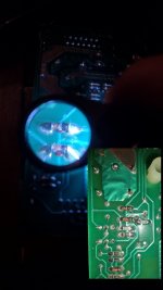
Phillips CD721 how do i adjust the current the laser gets
- Digital Source
- 2 Replies
I had the "no disk" error for years and multiple people on the internet recommended adjusting a screw were it adjust how much current is passed through go the laser can anyone point out it's location please
3-way tweeter upgrade
- By rdalem
- Full Range
- 6 Replies
I want to upgrade my 3 way active speaker with a better tweeter. Have celestion ftr15 3070c in Onken 360l, fostex 299 compression drivers such as mid, and BMS4538 as tweeters. I'm missing a bit at the top like crunch and details. The BMS is comfortable, but a little too kind.
A compression tweeter would be a good alternative to my JMLC 1000. Active sharing is currently set to 800Hz og 5000Hz.


A compression tweeter would be a good alternative to my JMLC 1000. Active sharing is currently set to 800Hz og 5000Hz.
For Sale Super Regulator by Jan Didden - finished
the regulator works perfect, only used in a test-configuration for a few hours, all parts from Mouser
ask for 55 Euros SOLD

ask for 55 Euros SOLD
Repairing a Musical Fidelity A1X
- By mz543578854
- Solid State
- 33 Replies
Hi, I love looking at descriptions and photos of repairs other people have done.
So I thought to give back to people also enjoying that.
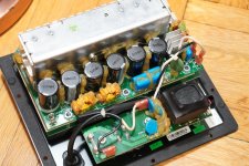
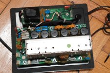
A little while ago, I bought a MF A1X, being in good optical condition, but the owner said it had suddenly stopped working.
He also said the source selector was not working well anymore.
When I had it on the bench, I saw that in the past someone had fiddled with it, and not too expertly.
The power cable had been replaced by one with a ground wire, although it originally was sold with "Schutzklasse 2" (Germany / EU), meaning no ground and internal high voltage being completely isolated.
The ground wire of that "new" cable was just screwed to the painted case. Not sure what the intention behind all that "modification" was.

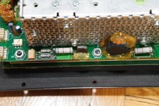
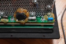
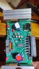
Power supply capacitors had visibly suffered. Other caps as well, see shrunken isolation on small electrolytic bottom right. I am not sure if these were the original caps or if they had been replaced before.

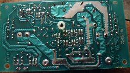
There were also other creative changes, like this strange wire, which was for fixing a broken PCB track (the PCBs of old MF equipment are real sh*t and tracks come off really easily).

Also not original was this "thing", maybe it was intended as part of some temperature circuit? It was not connected anywhere, though.

The sudden stopping to work was indicating the fuse was blown and it was. Testing after replacing it with a dim bulb tester showed a nice glowing lamp, so there was more.
I got out the board and tested the rectifiers on the PS first and indeed one of them had a short.

So I thought to give back to people also enjoying that.
A little while ago, I bought a MF A1X, being in good optical condition, but the owner said it had suddenly stopped working.
He also said the source selector was not working well anymore.
When I had it on the bench, I saw that in the past someone had fiddled with it, and not too expertly.
The power cable had been replaced by one with a ground wire, although it originally was sold with "Schutzklasse 2" (Germany / EU), meaning no ground and internal high voltage being completely isolated.
The ground wire of that "new" cable was just screwed to the painted case. Not sure what the intention behind all that "modification" was.
Power supply capacitors had visibly suffered. Other caps as well, see shrunken isolation on small electrolytic bottom right. I am not sure if these were the original caps or if they had been replaced before.
There were also other creative changes, like this strange wire, which was for fixing a broken PCB track (the PCBs of old MF equipment are real sh*t and tracks come off really easily).
Also not original was this "thing", maybe it was intended as part of some temperature circuit? It was not connected anywhere, though.
The sudden stopping to work was indicating the fuse was blown and it was. Testing after replacing it with a dim bulb tester showed a nice glowing lamp, so there was more.
I got out the board and tested the rectifiers on the PS first and indeed one of them had a short.
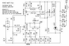
F2J JIG using Depletion Mode JFETS.
- Pass Labs
- 33 Replies
Hi All!
I'm looking at trying to cobble together an F2J JIG that I can test UnitedSIC JFETS with. I'm not looking for the magical "Triode" like behaviour or any special tones. Just an amplifier of around 5 Watts with a relatively low distortion figure and can drive 88dbw/M speakers 6 OHM. (Paradigm Signature Reference S2) I spoke with Mr. Pass (Papa Pass) and he stated I can just plug them in and tinker and warned me about using depletion mode JFETS (which I have studied in class A self biasing modes) in the f2J, however he chose a rare variety of enhanced mode JFET. I asked my professor about these and he said they don't exist and told me to start designing with common parts! So, I looked into it further and actually they are mostly normally off devices (the common JFET needs a few volts negative to turn it on!) well... yes.. hes correct in that ALL of our tests and labs we are using small signal JFETS which are only depletion mode devices and enhancement mode devices are usually strictly Mosfets and further I learned today that they are now discrete cascode MOS/JFET design. (UJ4C075060K3S) which is actually a JFET/MOSFET in the same package. 🤔
My main idea for this year end project was to demonstrate a small 5w Amp using PAPA F2J to my class but instead of trying to find or buy rare R100 Semisouth devices I wanted to use something common like depletion mode devices from UnitedSiC, biased in CLASS A with liquid cooling; more specifically these SiC depletion devices I found and are easily available to me: UJ3N065080K3S or UJ3N120070K3S
Using his production ready circuit and trying to "plug in" these devices will not work as the original F2J is using rare enhanced mode JFETS with positive bias on the gate, so...
My question what is the most elegant way to develop negative bias to the gate using a simple bench power supply? Obviously, Opening R4 and directing it to a negative voltage regulator source came to mind? Is there anything else I need to change in the F2J layout so that I can save some time and headaches with my project? I am seeking to demonstrate a low noise and low THD CLASS A amplifier with a liquid cooling system.
I hope to learn and build with modern Silicon Carbide or GaN devices so please go easy on me!
Thank you so much.
Jeff
Attachments
Mr. Wondercone & his wife Mrs. Magicdome having a new baby :)
- By Marveloudio
- Multi-Way
- 29 Replies
How should we call them? The wondrous magicians?
Now first here is the adopted baby from far east that will make you scratch your head about the plain ugliness :
https://sbacoustics.com/wp-content/uploads/2020/02/75-SATORI-MT19CP-4-GRAFIK.jpg
And Mr. Adopter himself with an answer in the comments : Login to view embedded media
So the answer is : The ROOM is healing everything! (any deficite)
Gosh! Never thought speaker development is so easy!
Some guys & girls have all the luck!?
Onkyo 838440089GR - SCREW 4TTB+8C(3BC)
Hi,
Does anyone know of somewhere in the UK or USA or anywhere I can find these screws? Literally can not find them anywhere...
Does anyone know of somewhere in the UK or USA or anywhere I can find these screws? Literally can not find them anywhere...
Sony Cinema Space DIY project using LA2615 AViSS 3D Surround Algorithm
- By rasansmn
- Analog Line Level
- 0 Replies
Enter the LA2615, an Analog Surround IC featuring the AViSS 3D Surround Algorithm a proprietary technology by SANYO Electric. This ingenious technology, initially commercialized by Sony under the name “Cinema Space” in their hi-fi audio systems, transforms a stereo image into a virtual surround sound, adding a new dimension to the audio experience.

While I stumbled upon a few applications of LA2615 in service manuals of hi-fi systems by Sony and Sanyo, I noticed a gap in DIY projects featuring this IC. Undeterred, I ordered the IC, which arrived in a compact SMD-type package instead of the one I intended. No matter, I decided to take on the challenge and implemented the circuit on a vero board, employing a bit of a hack to solder the IC.


With ample space in my amplifier cabinet, I easily found the place to locate it. I incorporated the surround sound circuit just between the audio input source and the tone-controller unit.

Notable aspects:
Read the full article on Medium: https://medium.com/@rasansmn/enhanc...2615-aviss-3d-surround-algorithm-c3da32d80949
Watch the short video of the full process:
Login to view embedded media
A demo:
Login to view embedded media
Any thoughts or questions? This thread is for you. Thanks.
While I stumbled upon a few applications of LA2615 in service manuals of hi-fi systems by Sony and Sanyo, I noticed a gap in DIY projects featuring this IC. Undeterred, I ordered the IC, which arrived in a compact SMD-type package instead of the one I intended. No matter, I decided to take on the challenge and implemented the circuit on a vero board, employing a bit of a hack to solder the IC.
With ample space in my amplifier cabinet, I easily found the place to locate it. I incorporated the surround sound circuit just between the audio input source and the tone-controller unit.
Notable aspects:
- The IC preserves the original tone of the music, ensuring fidelity.
- No unwanted reverb effect is added, providing a natural surround sound experience.
- True surround sound: The direction of the sound is distinctly felt, creating a spacious auditory effect.
Read the full article on Medium: https://medium.com/@rasansmn/enhanc...2615-aviss-3d-surround-algorithm-c3da32d80949
Watch the short video of the full process:
Login to view embedded media
A demo:
Login to view embedded media
Any thoughts or questions? This thread is for you. Thanks.
A manifesto for Audio DIY-ers
- By jan.didden
- diyAudio.com Articles
- 38 Replies
A manifesto for Audio DIY-ers
Edward T Dell (†)
Jan Didden
The title for this essay is borrowed from an Editorial that appeared in The Audio Amateur (now AudioXpress) some 30 years ago. It’s Owner, Publisher and Editor was Edward T Dell, a man who singlehandedly did more to promote DIY audio than anyone else I know. He was a great inspiration to me and ultimately responsible for my publishing and writing activities.
If you want to know what kind of man he was, read my interview with him at linearaudio.nl under My interview… I decided that after 30+ years, the Manifesto should be revisited. I have shortened it as well as updated it, in a few places, but tried to keep the same spirit. I am confident Ed wouldn’t mind at all, on the contrary. I thank the good people at AudioXpress, the copyright holders of the original, for allowing use of this material.
Who is this ‘audio diy-er’?
The most poorly maintained piece of equipment around most diyaudio workbenches is the guy who sits in front of it. Most of us ‘hang in there’ with this audio enterprise not because we feel confident of our ability or our knowledge or experience or skill but because we have a lot of hope and guts. And thousands of audio diy-ers have given up along the way somewhere and turned to golf, or bowling, or model railroading. They did so because of a number of reasons which we think must be sorted out if this avocation is to have any future.
The typical audio diy-er is a music lover whose appetite is partly satisfied by reproduced music. The pursuit of lifelike music in any particular place calls for a great variety of skills. Seldom are all of them present in one person. But the development of one or more of those skills is the substance of the audio diy-er’s avocation.
It may be speakers, and speaker construction that captivates those who usually combine a love for woodworking and a strong back.
The kit building diy-er sometimes develops a passion for kits like some people do for crossword puzzles. The kit maven searches for friends for whom he can build, or may even go so far as to set up a mail order kit building service for a price. At least he has found a way for his addiction to pay for itself.
The tinkerer has all the parts for some twenty-three projects gathered together on his basement shelves – all ready to be built – someday. Several other projects – in various stages of completion – also occupy his shelves. But little of his handiwork has found its way to completion or into his audio system – yet.
The modifier likes to customize. He’s built a few kits but is happiest when he’s changing a value here and there to make his equipment ‘his own’.
The general diy-er may have a little or any or all of the preceding types in him. He probably started in kits, has tried a speaker or two, has done some modification of his equipment, maintains it – most of the time – and has several partly finished and more ‘parts collected’ projects ready to do ‘when he gets a little time’.
The audio diy hobby requires a place to work. No matter how small – the table in the corner of a small apartment – or how big, which may be half a cellar full of benches and tools. It is the place the audio diy-er finds his fulfillment. The tools are as various as the wide range of related skills the diy-er must call on to do his work. Some diy-ers limit themselves, by preference or because they live in tiny apartments, to the basic hand tools and do little in the way of metalwork or original construction from scratch. Their test gear maybe limited to a meter, a generator, and a small ‘scope. Currently possibilities abound to design a metal case for your project, or indeed a complete multilayer PCB on your own PC, then ordering it through the ‘net. Nothing more is really needed to turn out projects that cannot be distinguished from what comes off a manufacturers’ assembly line.
Any diy-er will have to invest in test gear, construction tools, and materials. The serious diy-er keeps stocks of resistors, capacitors of a wide variety of vales and types on hand to try out a circuit idea he gets. He probably owns a small library of reference books which he turns to regularly for information.
The moment of truth
Every audio diy-er experiences a moment which sums up our whole reason for being what we are. The project is finished. You have checked it over several times. The terrible last moments of anxiety before turn-on are with you. You make a quick look – to again make sure the clippings are all shaken out, the connections are all secure, the capacitor polarities are all correct, the transistor leads are all properly oriented. That’s it. The loneliness, stillness, and anxiety of those last moments are nearly unbearable.
You flip the switch and one of three things happens: 1. Absolutely nothing; 2. a bright flash and a sickening smell; 3. a quiet hum, a reassuring LED coming on, and a fuse that stays intact. The test signal goes in, the wave pops up on the ‘scope screen.
Out of dread to ecstasy. No flight is faster, no distance further. No feeling is quite like this one. And it is what audio diy is all about. It is the central essence of what this hobby is all about. Our delight and satisfaction is something no one can understand who has not experienced it himself.
We are convinced that home craftsmanship is a vitally necessary development to our quality of life as a people in this post-industrial revolution era. Your pleasure and mine in the systematic exploration of the by-ways of audio with our minds and hands is a pleasure – and a journey we ought to cultivate. But what are the obstacles to that path of endeavor?
Ourselves, mostly.
Our most basic problem as audio diy-ers isn’t knowledge of electronic theory, it is knowledge of ourselves. If, when you turn on that switch and result No. 1 or No. 2 occurs, what you think of your own ability, and the kind of confidence you have in yourself is the most important consideration in the whole matter.
We have developed some suggestions about this game all of us should be playing for keeps.
First: believe that you can do the job. Despite the momentary setback, be sure you are going to come through this eventually. Never give in to the idea you are too uninformed, or stupid, to solve the problem sooner or later. It has an answer and you can find it
Second: do not think the worst. You will be strongly tempted to do so. Don’t panic. Decide ahead of time that things often go wrong. Electronic circuits are by nature, very intolerant of even small mistakes. They need to be nearly perfect to work at all.
Third: be sensible. Don’t work when you are overtired. Leave a problem overnight and come back to it fresh.
Fourth: ninety-nine percent of the problems of construction are simple errors on your part. A later, refreshed look at the problem may show you the error clearly and immediately. Don’t blame the designer. Troubles are very seldom engineering, although published articles do tend to have errors in them and it takes time to catch them. Be wary of projects which show signs of being based on theory or calculations or simulations only. Look for prototypes and some indication that the author has actually built what he describes.
Fifth: Audio Diy-ers, being few, tend to be loners, often out of necessity but sometimes out of lack of effort or because of personal preference. A friend who can go over your work – and whose work you can check – is a highly valuable and effective help with trouble shooting and morale. Even a non-audio type can help by listening as you go through the circuit and explain it to him. You can catch errors by verbalizing what you have done for him – and hearing yourself in the process. Of course, diyaudio is a limitless resource for this type of help.
Sixth: Check out the work systematically, follow a plan that is logical and do it step by step:
- 1. Check component values and polarity;
- 2. Inspect for cold solder joints;
- 3. Check for loose connections and intermittents;
- 4. Check your input and output cables;
- 5. Measure voltages for peculiarities and follow the clues to their source;
- 6. Follow the signal through the unit backwards from output to input for signs of life;
- 7. Systematically begin a check of components and substitute where you have doubts about the component;
- 8. Stay with it until you find the problem. Don’t ‘put it away’ on a shelf for a later day. It will stagnate and get cold – ending up as junk and mute evidence of your inability to deal with the problem;
- 9. Be aggressive. Intelligent caution is to be observed, but don’t let your fear of the beast make you unwilling to try things that will unravel the mystery.
What becomes obvious from the above list is that careful work habits, and high standards of construction practice can save a lot of headaches after turn-on. Unless they are new, check resistors for value, capacitors for value and for leakage or insulation.
Check transformers for continuity and power types for correct voltage (remembering that you are checking peak, unloaded values). Diodes and transistors can be checked for junctions with an ohmmeter – or the latter checked for gain on a tester. Be sure that reverse or blocking reading on the diode junction is high resistance too. That can be as important as the 10-20 ohms reading on the current passing connection.
Clean circuit boards just before assembling them and clean all component leads (except gold or silver flashed ones) by using a pair of diagonal cutters to scrape away the oxide from the tinning material. This speeds the soldering process and insures a good joint, quickly made.
Use a heat sink like X-Acto’s handy reverse tension tweezers on all semiconductor leads. It takes a little more time but is a good precaution against post-construction problems. Systematic, constructive thinking, perhaps out loud – or even on paper – is basic to finding troubles in electronic circuitry.
It is important to remember that a very modest store of theoretical knowledge can carry you a long, long way in this field. This is not to say we don’t all need theory knowledge, it I only to remind ourselves that the lack of such knowledge is no excuse for giving up on trouble shooting a piece of construction. Theory is important to design. Out-and-try experimentation can accomplish some things in design but good results are nearly all luck in such cases. But proper function of audio equipment is possible with modest amounts of information.
The same truth ought to give audio diy-ers without much formal training the needed courage to try projects on their own. That basic lack of confidence, with the feeling that one doesn’t know enough, keeps many diy-ers stuck in the shallow wading pool permanently.
Venturing into scratch building will give you new experiences, give you the chance to gain new knowledge, and send you on a search for new information. All of us are apt to look for new information when we have a pressing, practical reason for doing so. Trouble shooting can provide that reason if we keep our heads - and our courage – and press on to a solution. You will be surprised, as you push your way on through projects, how much information you pick up along the way. The knowledge is cumulative, too. The parts and ideas begin to fit together in a whole structure.
Every rule, of course, has its exceptions. Some of us seem to be born ‘all thumbs’. And for some conditions of that kind a few of us will simply have to accept in ourselves a permanent limitation. But much of that ‘all thumbs’ syndrome, however, seems to me psychological in origin with a basis which is mostly dependent on the opinion of the person about himself. Doubtless some of us are destined to remain onlookers for lack of manual dexterity, but though that limitation may close off original construction, it does not preclude some modification, maintenance and testing, nor all the pleasures of live recording.
This avocation of audio is worth the best efforts we can give it. Its value is far more than the pleasure of listening to superbly reproduced music. It is basically a satisfaction of one innate human appetite to create, to achieve, and to add one more artifact to the world’s collection of wonders. And the best of it all is that you did create that particular wonder yourself.
This forum you are perusing is meant to help every member to become an active, self-conscious, and in many instances articulate, audio diy-er. We ought to spread the word about this hobby among those who most certainly would enjoy its pleasures and satisfactions.
Let those who will, be content with what the merchandiser is willing to market. The audio diy-er is a different breed.
Tangband 5” Tapped tapered QW tube…
- By Booger weldz
- Subwoofers
- 34 Replies
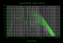
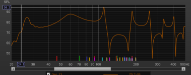
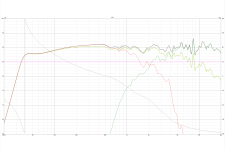
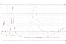
Not sure if these are ‘TL’ or tapped pipe? the sims and impedance plots are somewhere in between .
Did the horrible TS parameters and actual driver Fs of 59.4 (instead of 45) gimme that hump In the middle of the babdwidth?
Did the horrible TS parameters and actual driver Fs of 59.4 (instead of 45) gimme that hump In the middle of the babdwidth?
Attachments
-
 F1D375D5-19D3-414F-8537-09B9FF3A4418.jpeg623.8 KB · Views: 191
 -
 019FF6F7-3966-4C1B-B156-7D4B63999AF9.jpeg477.5 KB · Views: 191
 -
 91E2936C-18A3-46CD-812D-72418CB26944.jpeg454.7 KB · Views: 194
 -
 A568A0A8-F3E7-4D90-960A-4C3EFE9FB95C.png6.3 KB · Views: 177
 -
 5877CFB4-D876-4505-AC7A-1FF7C92CC8DA.png14.7 KB · Views: 191
powering TPA3116 with 24V - how much ampere
I am planning of making 8 channel mono amplifier using these mono amplifier boards
I will use 8Ohm 30W speakers.
How can I know/calculate how much ampere my PSU needs to deliver for all 8 amplifier?
I will use 8Ohm 30W speakers.
How can I know/calculate how much ampere my PSU needs to deliver for all 8 amplifier?
Tang Band W6-2313 - SUG2-25 based project
- By manuz74
- Full Range
- 4 Replies
Hi everyone
A while ago I found on the tang band website the SUG2-25 project based on the Tang Bang w6-2313 full range speaker. I was curious and decided to simulate the crossover given on the tang band website for this project. The thing is the graphs don't look very similar to the one given by tang band on this speaker project. Anybody had the same experience? Since I don't have the speaker I can't make any kind of measurement, but I tried to "fix" the crossover at least. Open to suggestions to improve the circuit!
The speaker is a 17 L box, with a 300x64 mm port. Also if anybody has better suggestions to use this full ranger let me know!
Attachments

Velodyne MiniVee sounds quiet and occasional popping sounds
- Class D
- 6 Replies
have 2 of these velodyne minivee subwoofers. 8"
one is producing bass but at very low volume levels.
moving volume knob up and down doesn't really help. volume level does not change. I seriously doubt its a dirty volume knob.
there are occasional popping noises. the driver jerks during pops.
visually things look ok. except 2 resistors that look like running hot.
hard to tell from pictures. but if you look close that part of the board is brownish. part where the 2 big blue resistors are and 2 similar smaller resistors.
anyone familiar with velodyne amplifier short cuts / optimizations. anyway to approximate wattage rating of those resistors?
a lot of people put more powerful resistors in velodyne amplifiers.
the large blue resistors are 16mm long and 5mm in diameter
small pair next to each other are 8mm long about 2.5mm in diameter
Attachments

Classe DR-8 Input Board Opamp Ugrade
- Solid State
- 7 Replies
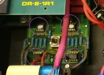
I'm helping a friend out with some upgrades on his pair of Classe DR-8 amps, which he has been using bridged as mono blocks for many years.
The input board of each amp has four opamps, however Classe went out of their way to remove the model numbers of them (see the attached photo).
My Classe CA-300 uses two dual opamps on the input board, so I'm assuming these CA-8's are single opamps. The schematic I was able to find online doesn't show the input board at all, and the service department at B&W (who now support old Classe products since the original Classe design and support teams were lost with company closure) don't have any documentation as to what opamps were used.
Does anyone here have a suggestion what these opamps might be? Based on the age of the amp there are probably better parts to use, but I don't want to mess with anything blind. Thanks in advance.
Attachments
decision fork: DSP vs passive?
- By neurotopia
- Multi-Way
- 98 Replies
Hi folks!
I’m at a fork in my next 3-way build, and I’m hoping for some feedback. I’ve already chosen drivers that will play very nicely with each other in terms of crossover design and I’m working on my cabinets. While I was mulling things over late last night, I got to thinking… “What if I went with a DSP instead of passive crossovers?” What makes the question hard -- for me -- is that I have a very nice SET tube amp I absolutely love. The amp wasn’t cheap and I’m not in a position to buy 2 more in order to accommodate the additional 4 channels of an active DSP configuration. Right now, my budget for crossover components or DSP (to include DSP and two additional amplifiers) is ~$1000.
This brings me to my immediate question: do the advantages of DSP with cheap DSP/amplifiers outweigh the advantages of a single, very high quality amplifier in a traditional, passive system with very high quality crossover components?
I know there are some strong opinions about passive vs. active/DSP and it isn’t my intention to open that can of worms in the abstract. I’m inquiring specifically for my build constraints and resources, which is the path of greater acoustic efficacy?
If the consensus is “go with good passive crossovers, for what you have now” then that’s easy. If folks think DSP would be better… well, that’s where my knowledge base tapers off. I’ve built a couple DSP/active systems in the past, but they were not what I would consider serious audiophile endeavors (sorry, I know that’s a loaded term): stock GUI/software (e.g. SigmaStudio or miniDSP stock interface) and “decent” class D amps. So... in the case of DSP/active, I have myriad questions (but I’ll start with just a couple):
1. For a high quality build on a limited budget, what DSP? A miniDSP Flex Eight? Or something else?
2. For programming the DSP, should I use the basic GUI/software or tackle more complex FIR stuff? Or start with one and build up to the latter? Oh, and full disclosure, I don’t know squat about building/implementing FIR filters -- but I’m willing to learn!
Thanks in advance for the feedback and for sharing your knowledge. 🙂
Unmarked failed diode in 1990 Volvo/Alpine 4x20w Amplifier
- By BilliamDIY
- Car Audio
- 6 Replies
Hi, folks. First post, but I'll try to make this make sense. I have some electronics repair experience but need a bit of help with this.
I've had substantial hum any time the incandescent headlights or ignition are on and static/clipping above a certain volume level especially on one side on a factory amplifier in a 1990 Volvo. Some people claim they were Alpine units. It is listed as a 20w x4 channel amplifier with Volvo part number 353004. The front speakers are 4 ohm and the rear are 8 ohm, which seems interesting.
The board is marked 55 11511-02 front and rear (front says Art No. in front of it). The rear is also marked 94V0 (looks like the board material) and w8939-Le and has 2 symbols. One is an F with ELEC above the center line and 3330B below, and the other is a mirror images LR with the vertical line of the R touching the bottom line of the L.
There is one 14-pin IC marked Portugal 8926BR and TL074IN. Looks like a 4-channel amplifier from TI (https://www.ti.com/product/TL074) but I don't understand the info on that page very well.
I took it apart and snapped some photos. I checked the glass case SMD diodes inside because 2 of 3 glass cases on surface mount diodes are cracked. Two test ok with a diode mode test reading of 538 and 539, but one of those has a cracked case. The third one tests with a value of 1850. None are shorted or open on a 2k-ohm resistance check. I know these aren't really meaningful values, but the big mismatch and very cracked case makes me think this diode could be blown. Then again, these readings have all been done with the parts installed.
Where I need help is I would like to replace these 2 or 3 diodes but I'm not sure what they are. The glass case makes me think Zener diodes. They have no numbers or identifiers on them even with a 20x magnifier loupe. I see only a black stripe on the end and a silver stripe in the center, which I don't see on any diode color code charts. In fact, I've seen several charts that list silver and say N/A. I've looked at some sites like Mouser but am not sure what voltage rating I should be looking for.
I found forum website from the BCAE1 website, and it has several photos of diodes exactly like this in amplifier circuits. Is this some sort of generic noise filter diode or does the info on the OP-AMP page give enough info to pick a voltage limit for replacement parts? Does anyone else have ideas on repairing this? I've tried to keep this car a budget driver while I finish my master's degree, and I'd love to not buy more than a few small components to keep the stereo working. I have another of the same amp like this, but I have little faith in it being in better condition than this one.
The suspect diodes on the back correspond to the front area with C03 T01 and T02 in the top left of the image I posted.
Thanks very much in advance!
William
Attachments
identifying valve 6N1 Pi-EB (an old useless rapirman cited them as 6DJ8 replacements?)
- By tonescout
- Tubes / Valves
- 63 Replies
Looking at some equyivalents it looks more like an ECC85, and not sure if this is able to be used as an equivalent to an ECC88?
any ideas, or is this another f** up by the repair guy, that I used before I started doing things myself!
Thanks
Rich
any ideas, or is this another f** up by the repair guy, that I used before I started doing things myself!
Thanks
Rich
Source for teflon caps
hi I am upgrading the caps in my 25 yr old Conrad Johnson P12 amp. I need values of 0.1 or 0.15 uf 600v. Can anyone recommend some good caps and a place to source them from? Thanks
A 6P13S sweep tube amplifier build
- By Bluesystems
- Tubes / Valves
- 11 Replies
I have been working for sometime on a basic push-pull power amplifier using the Russian 6P13S sweep tube and the 6F12P pentode-triode.
Recently I started testing my working proto type so I thought I would post some results in case there is interest.
The 6F12P pentode-triode was selected at the time I started as it has a high transconductance of S=19 allowing high gain and good bandwidth. The triode section although limited in peak current also has the same S=19 allowing it to track closely the pentode signal when used as a split load phase inverter. The result is high gain, low THD and wide bandwidth.
Unfortunately they have become harder to find with a lots now on the market that are used and too low in emissions to be of any use. Pity as it is a good tube and for personal reasons I am unable to buy from russia at this point in history while hoping for better times in the future.
Sweep tubes are interesting beasts as even the smaller sizes like the 6P13S given appropriate screen voltages they can deliver high levels of peak plate current. Often far higher than for example a typical 6L6.
The high peak plate current provides some benefits on musical peaks at both the higher and lower frequencies where higher levels of peak current can be required due to transformer and loudspeaker issues. A lot of tube designs measure great to 1KHz with sine waves into the designed impedance but struggle to produce musical peaks into off impedance loads like a real loudspeaker. At frequency extremes transformer issues can also limit performance due to lack of available peak current from winding capacitance at high frequencies or magnetizing inductance current at low frequencies.
So I though to see what a higher peak current sweep tube design would do designed into a 6L6 class power range of about 30Watts RMS. I did not use the larger sweep tubes as they have become expensive and hard to get but the 6P13S is still low cost. Admittedly it would have been easier to just use the trusty 6L6 but where is the fun in that?
There is reason to believe sweep tubes can be pushed past their rating with some confidence as they were designed to run hot at full power and very high peak voltage and current continually with years long reliability in TV use. Some old application notes suggested 40% over the sweep rating for audio use.
Most sweep tubes will not tolerate the high screen voltages that the 6L6, EL34 or KT88 will making UL operation a bit more challenging. Custom transformers with a separate screen winding is one solution but far too costly for this project. I used a screen connection for the 6P13S UL operation with the AC portion of the screen signal capacitance coupled from the output transformer UL tap and the DC screen current feed from a regulated DC power supply. As the sweep tubes are more sensitive to screen voltage changes I further reduced the UL AC signal level by a two resistor voltage divider and this provided the lowest THD of all versions.
This simulated and worked well on the bench and compared well to straight pentode operation. UL operation seemed at first to provide little advantage over straight pentode operation in distortion or stability until I noted output peaking at 500Khz occurred in the pentode version when the output load impedance was mismatched to the transformer.
This suggested that dynamic stability would likely be improved with the local feedback that UL operation provides in the output stage.
Below is the spice circuit and spice THD test results. Note total THD is highest with 40% UL operation and lowest with the UL AC screen signal reduced by 4. Total power output was a bit lower in 40% UL. Square wave response was unchanged.
All simulated at 30watts output into 8 ohms.
Pentode operation, regulated screen THD=0.1625187 PERCENT
40% UL, regulated screen THD = 0.4871198 PERCENT
40% UL level divided by 4, regulated screen, THD = 0.1262827 PERCENT
With UL screen drive reduced from 40% by a factor of 4 distortion dropped and power levels returned to near pentode levels. This UL version seemed a good compromise in added complexity in exchange for potentially improved stability.
In spice UL 8 ohm frequency response was -0.3dB down at 20Hz and -0.24dB 20KHz and with peaking down -11dB at 1Mhz frequency measured into 8 ohms and at 8,000 ohms load down -4.5dB ohms at 1.3Mhz suggesting stability. Note we are looking at a audio amplifier's frequency and phase response up and into the Mhz. This has nothing to do with reproducing these frequencies but does give clues as the stability of the amplifier. You will note I look down to below .1Hz and well above 1Mhz in the plots. There is much going inside in a audio amplifier that happens far outside frequencies that audio test equipment can measure that is important in how a amplifier will sound when dealing with dynamic transients found in music. Spice makes seeing this easy but a lab setup to measure this on the bench is no easy task.
I created the spice models for the tubes using a Utracer 4+ to collect detailed data on the tubes and then Ronald's modeling software to create the spice models by measuring actual sample NOS tubes. Wonderful tool but there is a learning curve in creating models with this software. Highly recommended and well worth the effort.
Power output in spice was about 30 watts with THD at about 0.126 % and
bench testing showed that was not far off the real world with the proto type producing 26 watts at 0.094% THD at 2KHz and at 1 watt 0.0177% THD. The actually bench voltage rail being a bit lower than I used in spice could be why the power level is down a bit.
20Hz testing produced 26W @ 2%, 10W @ 0.478% and 1 watt @ 0.167%
200Hz at 1W @ was 0.0369%
20KHz produced 26W @ 1.3% and at 1 watt @ 0.198%
Square wave response in spice at 1Khz looked very clean with no ringing or over shoot and nice sharp edges.
Bench testing at 20Hz, 200Hz, 2KHz and 20KHz shows nice sharp clean edges confirming stable wide bandwidth.
The 20Hz square wave apart from the strong tilt due to low frequency loss shows monotonic lines suggesting a absence of saturation, strong non-linearity's or instability in the transformer and feedback loop a this very low frequency.
The 200Hz square wave has clean edges with modest tilt and no ringing or over shoot.
At 2Khz the square wave is very fast and clean with perhaps a tiny over shoot so small it could be a artifact of the scope probe setup (I did not take the time to calibrate the scope probe). 20Khz square waves are starting to show some loss of rise time but again are very well behaved with perhaps a small amount of leading edge over shoot. Considering this 20Khz waveform went through a great big hunk of copper and iron to me this is impressive and suggests the Hammond 1650T transformer used are very well designed and made.
If there is interest I will post more detail of the PCB layout and the actual PCB proto type amplifier circuit diagram as well as the regulated power supplies used for this project.
Attachments
SE amp output to speaker w/ high pass crossover, and to ‘high level input’ for bass amp
- By beancounter
- Tubes / Valves
- 8 Replies
Putting together a new horn & flea power system for my daughter and her husband. One approach I am investigating is using an SE 45 amp, driving:
- a horn speaker setup from about 300hz up, which has a conventional speaker level high-pass crossover.
- a plate amp (likely Hypex) for the bass horn below 300hz, using the plate amp’s ’high level input’.
my concern is: will I have issues with the load that the SE 45 amp sees? Potential distortion of lower frequencies not having a conventional load? Or am I overthinking things?
The speaker level input to a Hypex amp and managing the bass with software is an awfully appealing approach, makes things very simple. At least until the tech changes and the outdated hardware/software bricks the amps…
12 opamps chained - measurements
- Analog Line Level
- 157 Replies
So a while ago I designed and made up a little pcb with 6 NE5532's (TI branded), constituting 1 non-inverting buffer then 11 unity-gain inverting stages. The idea was to purely test the cumulative effect of 12 opamps.


Recently I've actually got some equipment (Focusrite Scarlett Solo) that can have a stab at decent measurements of the setup.
I generated various test signals as WAV files including a six-tone (non-harmonically related) intermodulation test signal, which is somewhat closer to a typical music signal than a single 1kHz tone:


The comparison with a loopback and the string of 12 NE5532 stages is quite revealing:


The few places the green NE5532 plot emerges above the loopback plot seems to be a 16kHz spur (presumably ADC or DAC artifact), and the mains harmonic noise at low frequency (the setup is not screened and strewn across the desk alas).
The tiny peaks present in both the loopback and NE5532 output are presumably due to quantization of the WAV file, they are IM products at low levels I think.
So the performance of the Scarlett Solo is insufficient to distinquish 12 opamps in a row from a piece of wire. Or put more positively NE5532's are hard to beat.
There is a possibility some of the LF spurs are frequency difference peaks, but there's no evidence of 2nd order frequency-sum spurs or of 3rd order spurs above the noise-floor.
I was recording at 96kSPS and 24 bit, I think the waveform file may be 16 bit though. The amplitude was a moderate line-level, I forgot to make a note of it alas.
I post-processed the output using Python's scipy.signal library to normalize the levels and compute the spectrum (using the scipy.signal.welch function), and employed a very accurate flattop window to ensure the peak heights were right, its the HFT144D window from this excellent paper: https://holometer.fnal.gov/GH_FFT.pdf
I realize in retrospect I should have made jumpers on the board to allow more stages to be non-inverting and thus subject to common-mode distortion, not just the first buffer, as that would be an interesting comparison.
Recently I've actually got some equipment (Focusrite Scarlett Solo) that can have a stab at decent measurements of the setup.
I generated various test signals as WAV files including a six-tone (non-harmonically related) intermodulation test signal, which is somewhat closer to a typical music signal than a single 1kHz tone:
The comparison with a loopback and the string of 12 NE5532 stages is quite revealing:
The few places the green NE5532 plot emerges above the loopback plot seems to be a 16kHz spur (presumably ADC or DAC artifact), and the mains harmonic noise at low frequency (the setup is not screened and strewn across the desk alas).
The tiny peaks present in both the loopback and NE5532 output are presumably due to quantization of the WAV file, they are IM products at low levels I think.
So the performance of the Scarlett Solo is insufficient to distinquish 12 opamps in a row from a piece of wire. Or put more positively NE5532's are hard to beat.
There is a possibility some of the LF spurs are frequency difference peaks, but there's no evidence of 2nd order frequency-sum spurs or of 3rd order spurs above the noise-floor.
I was recording at 96kSPS and 24 bit, I think the waveform file may be 16 bit though. The amplitude was a moderate line-level, I forgot to make a note of it alas.
I post-processed the output using Python's scipy.signal library to normalize the levels and compute the spectrum (using the scipy.signal.welch function), and employed a very accurate flattop window to ensure the peak heights were right, its the HFT144D window from this excellent paper: https://holometer.fnal.gov/GH_FFT.pdf
I realize in retrospect I should have made jumpers on the board to allow more stages to be non-inverting and thus subject to common-mode distortion, not just the first buffer, as that would be an interesting comparison.
Happy Holidays !.
- By xXBrunoXx
- Solid State
- 1 Replies
Happy Holidays everyone !, have a nice time doing what you love .
And speaking of that, anyone enjoying some diy in this period?.
Talk here if you're working on something, share with us!.
- I'm a noob on this forum, for a while now, and I appreciated most of the people, responses, time , dedication. it's a nice place !., wanted to wish you all nice holidays and a great life!.
- Bruno.
Fostex FE203 Sigma
- By TRJC
- Full Range
- 9 Replies
I am looking for any information on FE203 Sigma. It seems these were produced shortly in 1983 (or around this time). What would be difference to FE203? Or maybe to FE208 Sigma? I would appreciate any detail you may have. Also about enclosures intended by producer.
Voltages Zen V8
I've been trying to build a Pass Zen v8 in a 80-ies Yamaha A-700 chassis as my first attempt at building an amplifier from basic components. When putting the plug in the AC socket (which was admittedly a bit scary), there was no magic smoke, no loud bang and the positive rail indicated +48.5V DC. Pffew!

Per instructions I then slowly increased the resistance at trimmer RV1 (called P1 in figure 10 of https://www.passdiy.com/project/amplifiers/zen-variations-8), and low and behold: I arrived at +25V at point J1. This is also good and made the lamps glow and a current of 2.01A was flowing through the lamps into the drain of Q3 (the IRFP 150N Mosfet), making the heatsink hot, but not scorchingly hot. So far, so good....

The problem I have is with the 9v indicated at J2 (which is the gate voltage for the Q3 Mosfet): I cannot get anywhere near the 9V I should get....
When I have 25V at J1, I only get 4.7V at J2 instead of 9V.
At point J3 (source of Q3 and drain of the LU1014D power FET) I only get 0.5V instead of the 4.3V I should get.
Increasing the resistance at RV1 will decrease the value at J1 and raise J2 a little, but even if I turn RV1 all the way up, I won't even get to 6V on J2.
I tried using only one lamp which would give about 23,4Ω resistance and 1A of current through Q3 instead of 2.01A, I've changed R1 into 47K and 20K, but nothing seemed to help: I never seem to get J2 at even 6V, let alone 9V.
Maybe I made a stupid mistake that I keep overlooking... Anyone any ideas?
NB: I bought the LU1014D power FETs on Ebay and I don't know if they are genuine and if that may be causing trouble. All other components are from respectable vendors.
Per instructions I then slowly increased the resistance at trimmer RV1 (called P1 in figure 10 of https://www.passdiy.com/project/amplifiers/zen-variations-8), and low and behold: I arrived at +25V at point J1. This is also good and made the lamps glow and a current of 2.01A was flowing through the lamps into the drain of Q3 (the IRFP 150N Mosfet), making the heatsink hot, but not scorchingly hot. So far, so good....
The problem I have is with the 9v indicated at J2 (which is the gate voltage for the Q3 Mosfet): I cannot get anywhere near the 9V I should get....
When I have 25V at J1, I only get 4.7V at J2 instead of 9V.
At point J3 (source of Q3 and drain of the LU1014D power FET) I only get 0.5V instead of the 4.3V I should get.
Increasing the resistance at RV1 will decrease the value at J1 and raise J2 a little, but even if I turn RV1 all the way up, I won't even get to 6V on J2.
I tried using only one lamp which would give about 23,4Ω resistance and 1A of current through Q3 instead of 2.01A, I've changed R1 into 47K and 20K, but nothing seemed to help: I never seem to get J2 at even 6V, let alone 9V.
Maybe I made a stupid mistake that I keep overlooking... Anyone any ideas?
NB: I bought the LU1014D power FETs on Ebay and I don't know if they are genuine and if that may be causing trouble. All other components are from respectable vendors.
Source for Wonder Caps?
I am looking for capacitors to correct an issue with a cross over on one of my IRS Beta speakers.
I need:
I appreciate leads/links
Cheers! Juan
I need:
- WonderCaps 10uf 310V X 7502A
- WonderCaps .01uf
- Solen PB 5100 51uf 150VAC
I appreciate leads/links
Cheers! Juan
Technics SL-1210MK2 - weird speed problem
- By mnsh
- Analogue Source
- 152 Replies
I have a strange problem with an SL-1210MK2 turntable. Things work perfectly when turned on - rotation speed is stable, pitch control works fine, sound output is fine.
A couple of minutes after turned on and started, the platter starts "losing it" - speed jumps up and down when the pitch control is near -8%. At this point the pitch control works fine in the range -6% to +8%. The speed jumps slowly spread to the rest of the pitch control range and maybe 10 minutes after the platter is started, it is just rotating really fast.
Changing the pitch control slider with a new one (I had a spare) makes no difference. The voltage selector is on the correct setting (220V).
Any idea where this problem could be?
thankful for any suggestions,
m.
Replacing power cord - surgeX innards
- By Ang
- Construction Tips
- 3 Replies
Hello - Picked up a cheap surgex unit, and planning to replace the damaged power cord.
Questions:
Any massive current storage in these units that I need to be wary of?
For the shielded replacement cable, do I just sort of gather up the shielding and attach to the ground nut?
Thanks!


Questions:
Any massive current storage in these units that I need to be wary of?
For the shielded replacement cable, do I just sort of gather up the shielding and attach to the ground nut?
Thanks!
Q1, Q2 Part Identity, QUAD QC Twenty Four?
- By ampexperts
- Solid State
- 4 Replies
I've a Quad preamp with impulse noise. At first I suspected the single 6111W dual triode, and replaced that, however, the noise the left channel continues.
This transistor seems to be in the left channel signal path. I thought it was only the tape out buffer, but not sure--lack a good schematic.
I've replaced the 7805 regulator already, but the noise continues. It's mostly left channel domimant with some cross talk of lower frequency to the other channel.
The part number seems to be an internal part number. VN10LP is a diode part number, but the schematic I have shows transistors a this location. Any idea what transistor Quad used here? Or a good cross reference?
Port length and baffle thickness
- Subwoofers
- 4 Replies
Hello all
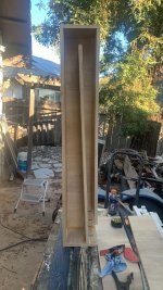
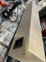
I have a box under construction which has a front slot that bends 90 degrees inside. Below is the pic. Currently, the baffle is 16mm. I need to increase this to another 40mm to total 56mm. Do I just shorten the port wall 40mm from the back?
I want to leave the driver at 16mm and have it recessed by 40mm so that I can have a flush grill and leave plenty of space for its crazy excursion
Uses for Ampex input transformers in a DIY build
- By Gonecat
- Tubes / Valves
- 11 Replies
Hello all,
I'm back after a long sortie and going through my 14yr old storage unit of project materials.
Came across two input transformers that I'd love to have your thoughts on (how do they sound? what applications are there for them?).
I have a germanium transistor preamp build going on and I'm curious about popping one of these in the front of it.
Or, how about a D.I., or a transformer color box? Has anyone used these types of transfos in a build?
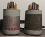
They are both Ampex and never used.
I searched their part numbers but at first glance found very little info on them.
4580200-01 Bridging input
4580116-20 Matching input
Much thanks for your thoughts!
I'm back after a long sortie and going through my 14yr old storage unit of project materials.
Came across two input transformers that I'd love to have your thoughts on (how do they sound? what applications are there for them?).
I have a germanium transistor preamp build going on and I'm curious about popping one of these in the front of it.
Or, how about a D.I., or a transformer color box? Has anyone used these types of transfos in a build?
They are both Ampex and never used.
I searched their part numbers but at first glance found very little info on them.
4580200-01 Bridging input
4580116-20 Matching input
Much thanks for your thoughts!
Attachments
Why stream 24bits when 16bits is the gold standard?
I am cancelling my Spotify premium because the sound is not premium. Now I am testing Qobuz which sounds better even with just 16bits CD quality which seems to be the gold standard for music distribution. Qobuz has many albums, even some from 40 years ago, marked as available in 24bits. But if I select the 24bit option it sounds exactly like the 16bit. I am using a Schiit Modi III DAC and Oppo PM-3 headphones.
24Bit promises much better performance than 16bit which is probably improves editing by the recording engineer-artist. But I wondering what gets stuffed in these extra bits when remastering old music from the previous century. Is the high-res badge just a marketing gimmick? A waste of internet bandwidth.
I would like to have some demo recordings where I can hear 24bits better than 16bits and/or MP3.
Here are some relevant links:-
QSC Powerlight 4.0 going into protect
- By shaddai
- PA Systems
- 4 Replies
Purchased a PL4.0 amp, and wired it into my system to drive a couple of Keystone cabinets. Sounded great, pushed on it a little and the first time it blipped the clipping LED, the protect circuit lit up, the amp restarted & it gracefully picked up where it left off. A day later it would do it running on a solid -10 LED, no clipping LED needed. Also noticed the gain on the left channel is about 2db hotter than the right if that matters.
Exchanged the amp with another PL4.0 & have no such behavior from that one. It's as solid as a rock. Dug through the PL4.0 service manual & it says nothing addressing a protect circuit kicking in early. Anyone ran into this before & could tell me where to start looking in there?
Todd
Exchanged the amp with another PL4.0 & have no such behavior from that one. It's as solid as a rock. Dug through the PL4.0 service manual & it says nothing addressing a protect circuit kicking in early. Anyone ran into this before & could tell me where to start looking in there?
Todd
Lo-Fi Beer Can Microphones - Darwin Audio
- By Darwin Audio
- Vendor's Bazaar
- 0 Replies
My name is Darwin and I run a one-man DIY microphone company, Darwin Audio, where I upcycle vintage, steel soda and beer cans from the 1970's and earlier (the really strong, uncrushable kind of cans).
These steel cans make perfect reverb chambers and securely house a piezo crystal pickup with a 1/4 inch out.
Extremely unique and rare designs since they no longer stamp these types of steel cans, so once these are gone, they're gone (and I'll have to find a new hobby).
Browse my Reverb store for $70 (free shipping) options, or inquire about a custom design at www.DarwinAudio.net (your region likely had breweries around at that time...)
.jpg")
Login to view embedded media
These steel cans make perfect reverb chambers and securely house a piezo crystal pickup with a 1/4 inch out.
Extremely unique and rare designs since they no longer stamp these types of steel cans, so once these are gone, they're gone (and I'll have to find a new hobby).
Browse my Reverb store for $70 (free shipping) options, or inquire about a custom design at www.DarwinAudio.net (your region likely had breweries around at that time...)
Login to view embedded media
Arcam Delta 290 Mains And Power Stage On LTSpice
- By Roppu
- Solid State
- 53 Replies
Hi.
I have an Arcam Delta 290 that I've just recapped and I've found some other problem too. Some resistor broken... I broke the copper rivets that connect the filter capacitors to the back side of the PCB, as I'm a beginner with diy soldering and desoldering, and I'm waiting for the spare rivets to arrive. Actually there's something more but I will tell in another moment.
In the meantime, I wanted to learn how to use LTSPice and I thought starting with the mains and power stage I'm working on would be good as I could get the several voltages for checking.
This post of @Mooly got me started but I'm drawing it trying to keep it as much similar as possible to the service manual, even because I'm not that good in electronics and I can't replace branches of the diagram with equivalent circuits.
Other than still needing to find LTSpice models for certain components, I'm wondering how the crossing wires of the diagrams should be considered: connected/not connected? Should you Mooly read this, I'd really be grateful if you told me how you did discern the touching from the non touching crossing wires.
I gave the variable resistor RV1 a fixed value that I change time by time to test the IQ across R1 but that voltage doesn't change, therefore something must be wrong.
Thank you!
![CropperCapture[7].jpg](https://www.diyaudio.com/community/attachments/croppercapture-7-jpg.1238398/ "CropperCapture[7].jpg")
I have an Arcam Delta 290 that I've just recapped and I've found some other problem too. Some resistor broken... I broke the copper rivets that connect the filter capacitors to the back side of the PCB, as I'm a beginner with diy soldering and desoldering, and I'm waiting for the spare rivets to arrive. Actually there's something more but I will tell in another moment.
In the meantime, I wanted to learn how to use LTSPice and I thought starting with the mains and power stage I'm working on would be good as I could get the several voltages for checking.
This post of @Mooly got me started but I'm drawing it trying to keep it as much similar as possible to the service manual, even because I'm not that good in electronics and I can't replace branches of the diagram with equivalent circuits.
Other than still needing to find LTSpice models for certain components, I'm wondering how the crossing wires of the diagrams should be considered: connected/not connected? Should you Mooly read this, I'd really be grateful if you told me how you did discern the touching from the non touching crossing wires.
I gave the variable resistor RV1 a fixed value that I change time by time to test the IQ across R1 but that voltage doesn't change, therefore something must be wrong.
Thank you!
NE5534 &NE552 line buffer shematic to approve
- By Gvida
- Analog Line Level
- 11 Replies
I Got a PCB, with no parts (line buffer) based on NE5534 &NE5532. Looking at the schematic of the first stage (Follower) I am very surprised by how the offset adjustment and the unitary gain are treated.
1- Is it usaal to inject voltage in the Vin+ to adjust the offset ?
2-Normaly compensation is done with a capacity not a resitor (points 1 & 8)
any comment ?
Thanks a lot
Georges

1- Is it usaal to inject voltage in the Vin+ to adjust the offset ?
2-Normaly compensation is done with a capacity not a resitor (points 1 & 8)
any comment ?
Thanks a lot
Georges
F5 boards (not diy audio) and parts
- By Chrisr3521
- Swap Meet
- 1 Replies
This has been on my shelf for a while, its time to move them on,
Circuit boards, amp cards (x2) are not official diy audio ones neither are the power supply ones (x2)
Parts look to be the diy audio kits, matched transistors etc, as you can see from photos the low wattage transistors have been installed already.
Transformer is a Block branded RKD400 2X18v, again as new never used.
Looking for £90 ovo plus shipping from UK
Attachments
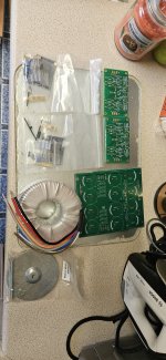
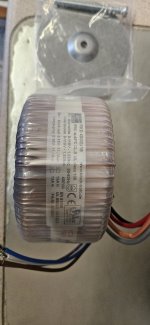
Name a really quiet JFET complementary pair?
- By cvanc
- Electronic Design
- 3 Replies
Application is moving coil stepup. Want to make the classic Leach common base circuit but with modern quiet FETs.
https://leachlegacy.ece.gatech.edu/headamp/
I'm shopping for the P channel first as it's far scarcer. So far I've found the LSJ74 which looks good but as usual noise shopping is an uncertain science. What JFET pair would you use for small signal jobs and specifically for this circuit? Thanks much...
https://www.linearsystems.com/jfetamplifierssingles/lsj/sst74-series
Pete Millett web page
- By alexberg
- Electronic Design
- 3 Replies
P. Millett site is down.
Is there a particular reason for that?

Is there a particular reason for that?
How do you "illuminate" your workshop?
- By jackinnj
- Equipment & Tools
- 62 Replies
In working on an SSB/AM/CW receiver in the OH workshop I had to take out the CFL's which were left by the prior owner, and replace with industrial 150W incandescent bulbs.
It's a prosaic issue, and many on this forum do work in RF -- what do you use to light your workshop?
It's a prosaic issue, and many on this forum do work in RF -- what do you use to light your workshop?
whitch int/amp Nelson Pass
- By bjcwolters
- Pass Labs
- 1 Replies
Hello ,
In need some help ore inf about a INT/AMP from nelson pass.
I, am playing with full range speakers PHY-HP 21 SAG 16 ohm 98 db.
at this moment i have 4 amps
1. tube 45SE (nice but not so muce bass)
2. Sansui au 919
3. Sony Ta-f7 V-Fet
4. Valvet stereo amp class a 30 watt.
I reed a lot nice things about Nelson Pass.
But there are so much models ;-))
It can also be second hand.
It is in Germany not so easy to lisening to different models .
Thanks for help.
Bart Wolters.
WTB AD1862 x2
- By Chrisr3521
- Swap Meet
- 3 Replies
I'd like to try and build Miro's r2r dac but want to source the dac chips first so looking for 2 x Ad1862 dac chips with shipping to the UK.
My compact party setup - Active THAM12 & 4" fullrange line array
- PA Systems
- 45 Replies
Long time I haven't posted anything on diyaudio forum, but would like to share my latest build experience anybody who is /or would like to build similar compact setup for any purpose.
Last year, I had an urge to build small, compact system, that will be used mostly as party system for our private events , for up to 30-50 persons (birthdays, celebrations of any kind,etc.).
My goals were relatively specific:
As I am on this forum for 18 years (ufff, time really flies), I've collected quite a few ideas, that definitely helped to speed up choice of each component.
Before I start with further explanation, I would like to thank first to Mr. Martinsson, as his work on THAM-series was the main cause why I went with THAM 12 route.
Additionally, he also experimented with line array columns based on small fullrangers, which I wanted to explore as well.
So the building process went like this:
1.) Bass bin/ subwoofer choice:
As I wanted to have relatively compact system based on tapped horns, I was aware that I will have to sacrifice low end extension.
Initially I was aiming for THAM 15 or Jbell SS15, which have better extension, but then I settled down eventually on THAM12.
Considering that now this is 10 years old design, there are plenty of tested drivers that are suitable for this box.
2.) Line array column:
In last years, at home I mostly listen to fullrange speakers anyway (my home system is based on LX Mini speakers, with Hypex DSP & amps) , and I am pleasantly surprised by modern fullrange drivers.
As there was lot of good reviews on "FaitalPro" small fullrangers, I decided to go with that route => so my column line arrays will be based on 12 Faital Pro 3fe35 per each side.
3.) Plate amplifiers with DSP:
There were many combinations, from making my custom plate amps by combining amplifier kits & DSP kits, but in the end when all costs are calculated, the best solution was "Hypex" FA502 plate amp => one plate amp would be installed on back of each THAM12.
As each FA502 can produce 2x350W on 8 Ohm or 2x500W on 4 Ohm, this should be sufficient for my purposes, as I don't require 140dB+ SPL.
So Channel A would power THAM12, and Channel B would power column speaker.
In case that THAM's would require more power, I could simply rewire each FA502 to bridge mode and power each THAM 12 with 1200W , but would then require external amp & DSP for line array.
4.) Initial design:
THAM12 dimensions are already known, and I kept them original the only things that I have modified:
The fullrange column box design was a little bit more involved, as I didn't use completed plan, but checked various recommendations on 3FE35 boxes, and checked dimensions of various PA manufacturers which use similar small fullrange drivers, and in the end created custom design.
Of course, designing closed box alignment is much more forgiving, than designing TH, especially as I have DSP available, so I didn't worry too much about that.
The most important things that I wanted to implement:
Last year, I had an urge to build small, compact system, that will be used mostly as party system for our private events , for up to 30-50 persons (birthdays, celebrations of any kind,etc.).
My goals were relatively specific:
- To have fully active system , with integrated DSP,
- To have two smaller bass bins/subwoofers and two satellites,
- To have line array based on column of fullrange speakers,
- To have bass bin/subwoofer based on tapped horn design,
- To be able to produce up to 110dB SPL on 10 m distance,
- To use robust but affordable PA drivers,
- Most important, to have very good sound quality,
As I am on this forum for 18 years (ufff, time really flies), I've collected quite a few ideas, that definitely helped to speed up choice of each component.
Before I start with further explanation, I would like to thank first to Mr. Martinsson, as his work on THAM-series was the main cause why I went with THAM 12 route.
Additionally, he also experimented with line array columns based on small fullrangers, which I wanted to explore as well.
So the building process went like this:
1.) Bass bin/ subwoofer choice:
As I wanted to have relatively compact system based on tapped horns, I was aware that I will have to sacrifice low end extension.
Initially I was aiming for THAM 15 or Jbell SS15, which have better extension, but then I settled down eventually on THAM12.
Considering that now this is 10 years old design, there are plenty of tested drivers that are suitable for this box.
2.) Line array column:
In last years, at home I mostly listen to fullrange speakers anyway (my home system is based on LX Mini speakers, with Hypex DSP & amps) , and I am pleasantly surprised by modern fullrange drivers.
As there was lot of good reviews on "FaitalPro" small fullrangers, I decided to go with that route => so my column line arrays will be based on 12 Faital Pro 3fe35 per each side.
3.) Plate amplifiers with DSP:
There were many combinations, from making my custom plate amps by combining amplifier kits & DSP kits, but in the end when all costs are calculated, the best solution was "Hypex" FA502 plate amp => one plate amp would be installed on back of each THAM12.
As each FA502 can produce 2x350W on 8 Ohm or 2x500W on 4 Ohm, this should be sufficient for my purposes, as I don't require 140dB+ SPL.
So Channel A would power THAM12, and Channel B would power column speaker.
In case that THAM's would require more power, I could simply rewire each FA502 to bridge mode and power each THAM 12 with 1200W , but would then require external amp & DSP for line array.
4.) Initial design:
THAM12 dimensions are already known, and I kept them original the only things that I have modified:
- Adding additional isolated space on rear side of the speaker for mounting FA502 plate amp,
- Adding aditional speakon connector plates,
- Adding M20 mount on top of the speaker (for pole mounting).
The fullrange column box design was a little bit more involved, as I didn't use completed plan, but checked various recommendations on 3FE35 boxes, and checked dimensions of various PA manufacturers which use similar small fullrange drivers, and in the end created custom design.
Of course, designing closed box alignment is much more forgiving, than designing TH, especially as I have DSP available, so I didn't worry too much about that.
The most important things that I wanted to implement:
- Dividing whole volume of cabinet in three closed spaces, to minimize vibrations,
- To mount edge of the drivers as close each other as possible,
- To have around 6 Ohm impedance (suitable for almost any amplifier),
- To have rear panel removable (in case I would like to change something internally).
Formatting lost when posting
- By Bluesystems
- Forum Problems & Feedback
- 9 Replies
I make a nice looking chart in the edit window.
I post the nice looking chart.
Sadly the posted result is now a chart that is a total mess as all the columns and words have shifted about making it very hard to understand.
Is there a way to over come this? Is this as good as computer editing gets in 2023?
Bob
I post the nice looking chart.
Sadly the posted result is now a chart that is a total mess as all the columns and words have shifted about making it very hard to understand.
Is there a way to over come this? Is this as good as computer editing gets in 2023?
Bob
Super Stereo Ears! Hear in Hyper-Stereo! D-I-Y
- By Pano
- Everything Else
- 4 Replies
I'm all hyped up about this. 😀
Being audio geeks you have certainly seen photos like this one:

There is a good collection of these photos about acoustic devices for aircraft detection in the days before RADAR.
https://rarehistoricalphotos.com/aircraft-detection-radar-1917-1940/
But have you ever wondered what one of these might sound like? Or wondered if the spacial acuity was actually enhanced? Well I did. Today I did something about it.

Hyper-Stereo for only $3.25 OK, I already had the mics, the headphones, the little Sony recorder - so all I bought were the clear spheres and some coat hangers.
Does it work? Yes, surprisingly well. Very pin point. When a source is directly in front of me, it's very obvious. And if the sound source is off to the side, it's very obvious to which side. Tested on birds, insects, cars down the hill through the trees, roosters, kids and the TV. All blazingly east to pinpoint. And to my surprise, I can tell when a source is behind me. Cicadas and small birds are very much easier to locate than without the rig. Maybe that's a frequency range limitation. I haven't used it to detect aircraft yet, because we get so few here. Maybe one a week, if that. But when that vintage twin engine Beechcraft survey plane flies over again, I'll track it.
BOM
Being audio geeks you have certainly seen photos like this one:
There is a good collection of these photos about acoustic devices for aircraft detection in the days before RADAR.
https://rarehistoricalphotos.com/aircraft-detection-radar-1917-1940/
But have you ever wondered what one of these might sound like? Or wondered if the spacial acuity was actually enhanced? Well I did. Today I did something about it.
Hyper-Stereo for only $3.25 OK, I already had the mics, the headphones, the little Sony recorder - so all I bought were the clear spheres and some coat hangers.
Does it work? Yes, surprisingly well. Very pin point. When a source is directly in front of me, it's very obvious. And if the sound source is off to the side, it's very obvious to which side. Tested on birds, insects, cars down the hill through the trees, roosters, kids and the TV. All blazingly east to pinpoint. And to my surprise, I can tell when a source is behind me. Cicadas and small birds are very much easier to locate than without the rig. Maybe that's a frequency range limitation. I haven't used it to detect aircraft yet, because we get so few here. Maybe one a week, if that. But when that vintage twin engine Beechcraft survey plane flies over again, I'll track it.
BOM
- 1X TASCAM headphone (closed)
- 1X SONY digital pocket recorder as mic preamp and headphone amp
- 2X PUI Audio POM-2730L-HD-R mic capsules
- 3X meters miniature mic cable
- 1X 1/8" TRS phone plug (for mics)
- 1 Clear plastic Christmas ornament
- 3 Wire clothes hangers
- Dozen Zip ties
- Glue (plastic hemispheres to coat hanger)
For Sale TPA Placid BP - shunt regulated bipolar DC power supply
selling a finished, working power supply, details on the website from TPA, it is the version 2.1.2
ask for 35 Euros

ask for 35 Euros
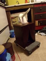
Gingertube's tube / valve recto sag simulator
- By maciekrus83
- Instruments and Amps
- 15 Replies
Hello everyone,
My first post here. So far I've just been lurking and learning from the wealth of knowledge people have been sharing in the forums here.
Now, to the point. I have successfully built a few different guitar amplifiers. All of them employ solid-state rectification, but recently I have been interested in hollow-state rectifiers for the voltage sag they offer. While searching for a way to emulate the effect without having to install another socket or worrying about the available heater current etc., I found posts about using a resistor in the power supply whose resistance is close to that of a given rectifier valve. Certain users, however, claim that the sag caused by a simple resistor doesn't feel natural.
I have also stumbled upon a schematic by diyaudio user Gingertube posted here
https://www.diyaudio.com/community/threads/power-scaling.251971/#post-3841280
Question #1: Has anyone, apart from its author, built this circuit?
Question #2: If so, how does it respond to playing? How does it "feel" compared to an actual rectifier valve?
I appreciate any input,
Maciek
Tube DAC with TDA1541 and 6Ж52П pentode (6J52P or 6Z52P ??)
- By TasoTaso
- Tubes / Valves
- 19 Replies
Hi, I have this DAC that comes out a little low compared to my other sources. Maybe I could change tubes with others with a higher MU..Clearly tweaking the polarization?
It features 2 pentodes connected to a triode with this acronym printed on it "6Ж52П".
Regarding the translation from Cyrillic, I honestly don't understand if they are 6J52P or 6Z52P, I would like your opinion on the matter.
I would also like to know the MU when connected to triode. Two links online lead me to this:
https://www.bartola.co.uk/valves/2013/11/17/6ж52п-6z52p-in-triode-mode/ (MU 76.5)
....and to this:
https://www.bartola.co.uk/valves/2015/07/04/lcr-phono-design-notes-part-ii/#more-4746 (MU 54.81).
In your opinion is it the measurement of the same valve? Because it mentions 6J52P in one link and 6Z52P in the other... and I don't understand why there is so much difference in MU. Maybe measurements taken under different conditions make that much difference?
Oh well..I would simply like to know the MU also to adjust myself with other possible alternatives, with higher Mu, such as perhaps a possible E810F, D3A..or 6z51p which has an MU of 80, visible at this link:
https://www.bartola.co.uk/valves/2013/02/23/russian-pentodes-in-triode-mode/#more-1264
Apart from the MU issue, partly to know how this DAC was implemented, partly to learn something, I still made some measurements around the tube.
Compared to the diagram the seller provided me, I notice several differences.
The DAC output pins go straight to the tube and, unlike the diagram provided, no transformer, no filter. There is only one r of 56/57ohm towards ground (I think it is for the I/V conversion)... and 1k as a grid stopper, if I'm not being stupid. Why is there no filter? Perhaps the miller capacity entering the tube is exploited to "generate" it?
For the rest there are no bypass caps on the cathode, so I can assume that I could gain output signal level by bypassing the rk with an electrolytic cap. But since, if I remember correctly, the signal passes through it, perhaps I would prefer to use some diode... LED... or another type.
Always hoping not to say nonsense. It's correct? with a diode, at the same voltage (1.1v) I should have maximum gain, right?
In fact I then noticed differences from the scheme. The B+ is not 180vdc as per the diagram but 151/154vdc.
The RA is 6.7k and, if I'm not doing the math wrong, the current flowing in the tube is (1.06v : 180ohm) ...5.88mA.
Given the way the tube bends are, whether it is a 6J52P or 6Z52P, it seems to me that it is working with little current and therefore also in a slightly unlucky area of the bends.
I'm highly inexperienced so I've been talking nonsense for a while. Furthermore, reading a lot online about this tube or similar... they seem to like much higher currents than a paltry 5.88 mA.
Was it a design choice to have a certain sound timbre?
Well, that's all. I haven't listened to the object much yet but I think it sounds very pleasant, very good, but it could be that we could do better, certainly.
First of all I would tend to try to increase the output level.
I'd love to get some help, some advice, some opinions regarding the current polarization and the other "points" I highlighted in the post if you have time!
Anyway, thanks for any words.
Attachments
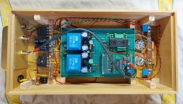

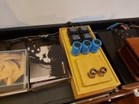
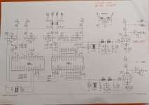

For Sale Preamp PSU from Birger Maaß / Audiopcb de
need more space for new projects, this power supply is nearly unused, it can be used as as two independent single supplies or as dual power supply,
the not very sexy material on the capacitors is used for stabilization and can be easily removed,
ask for 60 Euros


the not very sexy material on the capacitors is used for stabilization and can be easily removed,
ask for 60 Euros
Adcom 7400 schematic sought
- By al2002
- Solid State
- 9 Replies
Hi All,
I’m Looking for the schematic for the Adcom 7400 5-channel amplifier. The service manuals I’ve seen on the web do not include the circuit diagram.
Anyone know if there was a 2 channel version of this or a related multichannel amp? if so, info would be welcome.
Thanks in advance.
I’m Looking for the schematic for the Adcom 7400 5-channel amplifier. The service manuals I’ve seen on the web do not include the circuit diagram.
Anyone know if there was a 2 channel version of this or a related multichannel amp? if so, info would be welcome.
Thanks in advance.
100W CFA Class H (ClassA + ClassB)
- By dadod
- Solid State
- 17 Replies
This amplifier I built two year ago. It is Class A OPS bootstrapped by Class B.
It uses my OITPC compensation and it needs low voltage floating power supply for the Class A OPS.
It uses my OITPC compensation and it needs low voltage floating power supply for the Class A OPS.
Attachments
-
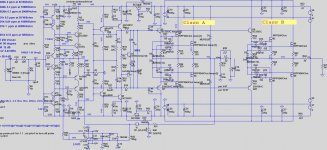 100W CFA ClassA+ClassB .sch.jpg154.2 KB · Views: 1,236
 -
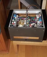 100W CFA ClassA+ClassB in play2.jpg270.3 KB · Views: 1,071
 -
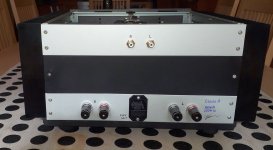 100W CFA ClassA+ClassB back.jpg188.1 KB · Views: 657
 -
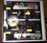 100W CFA ClassA+ClassB 4.jpg642.7 KB · Views: 592
 -
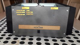 100W CFA ClassA+ClassB front.jpg304.6 KB · Views: 595
 -
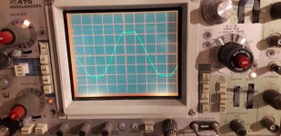 100W CFA ClassA+ClassB clipping.jpg207.1 KB · Views: 589
 -
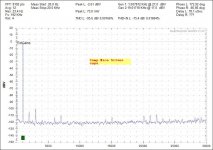 100W CFA ClassA+ClassB-SMica- THD1.jpg89.6 KB · Views: 589
 -
 100W CFA ClassA+ClassB IMD.jpg82.1 KB · Views: 1,067
Output transistors for Dyna ST-120?...
- By wacocg4a
- Solid State
- 56 Replies
Hi all...
I'm new to this forum, but far from new to DIY audio... (still have all my '70s vintage issues of Audio Amateur...)
Question... Recently I was given an old Dynaco ST-120. As expected, its non-functional and needs a complete re-build... and its an oldy... before the "TIP mod".
Now, I've brought several of these things back to life over the years, but its been at least 15 years since I've worked on my last one. So... what I'd like to know is what output transistors available today are people using to fix these?... I remember buying parts from an outfit in Ohio way back when that had all of Dynaco's old inventory, but they're loooong gone... and I also remember using 2N5630s (what Dyna put in their "400" if I remember correctly)... but those are now NLA (at least ones I would trust buying).
I've read of people using 2n3772s... but as with 2N3055s (which I've also seen people use) they don't seem to have the required ratings ( Dyna originally used a specially selected 3055s).
In reading on this forum and others, I've seen recommendations for MJ15003s, MJ802s and the previously mentioned 2n3772... but I'd love to hear input from anyone that's done a rebuild recently and hearing what they used and how they worked...
BTW... to ward off opinions as to whether this thing should be saved or not... Let me just say that I've built/owned/repaired several ST-120s over a 35 year span and know their pluses and minuses... this is just a nostalgia trip for me...
Thanks... jjw.
Introducing Mercury - Achieving escape velocity.
- By Russ White
- Twisted Pear
- 273 Replies
Hi Folks,
First I will say - thanks for waiting patiently for me to post - I have been very busy writing and testing B3SE-Pro firmware as well checking the other new modules.
I will start this post by describing why mercury exists… when I first got the datasheet for the ES9038 my first remark to ESS was “what in the world is supposed to convert that much current into voltage?” - actually that alone is not hard - but achieving it in a way that the DAC sees a virtual ground always - well it may not seem that challenging - but really it is very much so - and not just because most opamps can’t deliver that much power alone - but because of the nature of the signal. These DACs put out some very seriously strong common mode signals. That common mode stuff - well - it’s not the stuff you want to hear. 🙂 Rejecting that common mode stuff is not all that hard when you have plenty of negative feedback - but as current demand increases - so does control over the feedback loop.
Now keep in mind this common mode rejection thing is not a new challenge for me - I tackled it before with the ES9008/18 - but at a much smaller scale by using a fully symmetrical op-amp - and that paid off in spades - but really that solution is really only good for say 25ma p2p swings max (and that is pushing it). Of course you could use normal dual or single opamps - but there are some serious drawback to that approach. When you are dealing with a balanced source you need a fully symmetrical balanced transimpedance stage so that both the inverting and non-inverting inputs are literally symmetrically joined at the center or common mode - you can’t do that with two opamps - you need a truly balanced/symmetrical single amplifier. So armed with this hard won wisdom - I starting thinking in depth about the new challenges of this massive current I had been handed.
Of course - my first thought was much the same as the advice I got from ESS engineers - the inner voice said this: “Well Russ - the answer is simple - you have 4 times the practical max current - why not just use 4 transimpedance stages and sum the outputs?” Why not indeed… so hey - I tried it. Yep it works! And yep it sounds great - but man this output stage is huge!!! Not only that - but it is expensive!!! And it is also more complex that it really needs to be… So you might think I rejected this design - I did not - I just don’t think it’s for everyone - nor even necessarily “the best” I could do.
There was another problem… this solution required essentially using the DAC as a 8 channel DAC all the time. Well the vast majority of our DAC builders doing stereo or even mono DACs - I knew I could do better. I knew I could keep the simplicity of the Buffalo SE for stereo/mono users and still give them access to the ES9038’s full potential. To do that I needed a solution that allowed me to sum at the DAC - not after...
So I started a series of experiments - and it was some serious fun. 🙂 First - the naive solution was just to wrap the OPA1632 transimpedance with a pair of buffers… Sure enough that worked and gave pretty decent results - but right away I spotted some major flaws in this simplistic approach. Still my new DAC was making some seriously great music - so I listened and thought more critically... I knew I could do better.
The first flaw I spotted was that because the output common mode of the transimpedance stage output was set to 0V that stage was always under load, not a small one either… this made the thing run unnecessarily hot - and took away valuable feedback current. That problem alone would not have deterred me because it is not not hard to fix… if you have the AVCC voltage you can divide it (and buffer it) and set the output common mode to the mid point of AVCC - problem solved right? Well you would think - but no… First I don’t want to run AVCC to anything but the DAC because having long nets there is inviting EMI into the DAC. So I stewed on this over a cold beverage and… inspiration!!! I found something that not only set the input common exactly at the DAC’s DC operating point… but it actually solved the second flaw as well…
So I better describe that one too… The second flaw I found with the “basic buffer” approach was that the input common mode (even with VOCM set to AVCC/2) was not exactly where I expected… How could this be? sure it was close - but guess what... it turns out the output impedance of the individual DAC output elements actually has some variance (naturally - it's silicon) - this means error. The the DC operating point can vary (albeit very slightly) from part to part, but not only this - the operating point is dynamic! I observed this by placing a scope probe at the common input point and observed a sine wave at full scale at lower frequencies… This can’t be good… Oh... but that brings me back to the solution!
What we need is an effective error amp - basically a common mode servo that compares the common mode voltage at the transimpedance output to the common mode of the input - and then applies a the opposite of the error voltage to the VOCM pin of the OPA1632. Wow! Sure enough that did it! No more error signal on the input - and now the input looks more like a “perfect” virtual ground. I would not be able to do that without a truly fully symmetrical transimpedance stage. So take a moment and let this sink in - I now have a solution where I don’t even need to pipe in the AVCC net to set the input common to exactly the DAC operating mid-point (close to AVCC/2). No chance of injecting noise into AVCC - minimal error (basically just the voltage offset of the error amp)!
So that is not the end of it - first transimpedance stage itself is not enough - sure it does the heavy lifting - it converts the current to voltage - but what we really want is a low pass filter as well - because without it - well you are passing much more than music down the chain… Not desirable. So Just like the IVY-III I added a second stage which is a simple filter with about 2K input impedance and almost no output impedance - and options for 20Khz or 30Khz corner frequencies. This stage is free from the concern of driving the source load - it only has the ultimate load (and Bal to SE stage which is minimal) to care about. Because both of these stage have incredible CMRR what you end up with is an extremely low noise floor.
We also know that a huge percentage of builders still want single ended outputs - so we included a Bal/SE stage with it’s own servo and relay to prevent turn on/off thumps. Why a servo? Well because resistors have tolerances - and even .1% resistors are not perfect - so by applying error correction at the final stage we nullify those errors at DC. This can make a big difference especially if your power amplifier has a lot of gain and it is DC coupled.
Tomorrow I will start posting some more info - but this should be enough for you to chew on.
There is much more to the story - but it’s more than I want to say in one post. I have landed on three approaches I love enough to produce - Mercury is - I think - my best output stage so far - because it makes all of the ESS DACs sound better - even the ES9008/18/28. Yes it can handle massive current - but it also makes lower current DACs shine!
Until Brian or I have a chance post better pictures - here is a render of the 1.0 PCB - along with a shot of it playing in the test rig with a ES9038. 🙂
Cheers!
Russ
Attachments
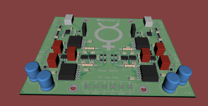
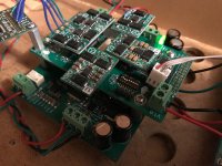
I am an absolute beginner....
I am trying to test the IC's in an amplifier with red probe on ground and the black probe checking each pin. Why do I get readings varying from 550 to 1700'. Am I doing it the right way. There are 12 chips in this amp and the readings are all over the place. I need help please........
RCA JAN CRC 5V4G Rectifier heater glow bright orange in preamp but work perfect.
- By eldad
- Tubes / Valves
- 6 Replies
hi friends, i bought this rectifier from ebay as nos for my 6SN7 Preamp ,all work and sound damn good, voltages ok,
and temp of the rectifier and power trafo also normal. no noise or hum.
the heater has very strong orange that glows twice brighter in comparison to Russian rectifier. boh work fine in this preamp
both 5 volt rectifiers and trafo sec for the rectifier heater 5volt too.
no red plate or blue/purple glow.
any reason to worry?
miniDSP plugin
Hey,
I recently purchased a pair of active speakers and I’m having an issue with minidsp. Apparently there is a license transfer required in order to download plugins from minidsp. I bought these from a private party and his setup is enough different that some adjustments are necessary before they will work. I think the issue is downloading the plugin. Once I clear that hurdle I should be able to adjust parameters and get them working. I thought I would be able to use them with the existing plugin but the speakers are showing an analog output which prevents them from operating through the digital outputs. From the minidsp forums it appears that to download the correct plugin you also need to be logged in and running a suitable operating system. I’m using a MacMini running High Sierra 10.12.6 with Safari as the browser which should be fine.
I think this issue can be cleared by getting the license transferred, unless I’m missing something? Please advise.
Thanks,
Jcris
Please Help Identify the Jazz I Like
Maybe I am a bit of an odd Jazz fan. There is Jazz I really love, Jazz I can tolerate, and Jazz I find simply unbearable. I am trying to find out if there is a name for the type of Jazz that I like, to make searching easier. Wondering if anyone here can help.
What I don't like: The really eclectic, "loose", improvisational, borderline random stuff. I have come to learn that some of the greatest Jazz artists of all time specialize in this type of Jazz. It simply isn't for me. I need something with some semblance of rhythm and beat, with a groove that I can settle into.
What I do like: Mostly instrumental, (although I don't mind some female vocal Jazz once in a while). I like Dave Brubek's "Take Five" (of course) - this is a good example of Jazz that still has a "hook", something with a groove that you can settle into and isn't simply random notes. Even a single artist might be known for this "improvisational" type of Jazz, but then I find gems by the same artists that I absolutely love.
Example: John Coltrane - I love songs such as "Naima" and his entire "Ballads" album (enough that I bought the 180g vinyl) but there is so much of his music that I can't handle.
I search for great Jazz artists and find the obvious ones, and then discover ever more random music that my brain simply can't comprehend.
So, what type of Jazz do i like? Is there a name for it? And no, I also don't love "Smooth Jazz". I don't find it completely annoying, but that's not what I am looking for. Oh, and I actually really like "Gyspy Jazz" when I am in the mood for something speedy.
Using YouTube as your ONLY test signal generator? Not as crazy as it sounds
- By cvanc
- Equipment & Tools
- 42 Replies
I'm gonna post a couple I've found and document why I think you can just use these instead of buying dedicated hardware. My postings here will all be taken thru an old 2 channel DAC I've got - not the latest by any means. This will not give you every signal imaginable but there are many.
Here's what seems like perfectly usable pink noise. The ten dB/decade slope is nice & tight all the way across.
Login to view embedded media
Here's what seems like perfectly usable pink noise. The ten dB/decade slope is nice & tight all the way across.
Login to view embedded media
Attachments
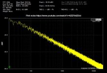
Feedback and Input resistor value
- By radio_free
- Solid State
- 18 Replies
Hi Everyone,
I am building a solid state power amp project (approx 60~80W), and need some help and opinion on the feedback and input resistor values.
See below image, I read somewhere that ideally the sum of R1+R2+R3 should equal or closed to the value of sum of R4+R5.
The values given to me were as Option1, but I do not have 22kR and 1.8kR in my box but have a bunch of 47kR and 4kR (all CMF55).
Is Option2 bad in anyway? My concern is if increasing the feedback resistor (R4) value too much will have any unfavourable effect, but maybe not since R4+R5 are just voltage divider?
Let me know you think and I wish everyone a wonderful Christmas and a peaceful 2024.
Attachments
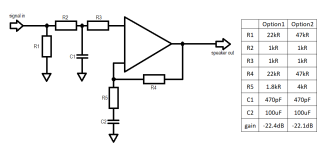
Alternatives to Belton Octal Tube Sockets?
- By TroutBear
- Tubes / Valves
- 2 Replies
I'm pleased with the Belton 9 pin PCB mount sockets used in my ST-35 amp and thought I'd get the same in an 8 pin socket for a SP14 preamp build project. But I can only located ones with mounting flanges attached - well attached, not easily removed. These may not create an interference, but thought I'd ask about simple format PCB 8 pin sockets of equal or better quality to gather alternative suggestions. Thanks
For Sale RJM Audio Emerald MM/MC Phono Stage
Reselling this RJM Audio Emerald phono stage built by member Itsikhefez. I've used it for a year and a half, unmodified and it works perfectly.
Asking $400 shipped to US addresses.
Asking $400 shipped to US addresses.
Attachments

For Sale F1J built + PSU
Here for sale is the F1J and PSU I built as described in this thread from post #297 on. The boards are UMS drilled and the amp fits nicely in a 4U Deluxe chassis with room for a separate transformer for each channel. Included is what's shown in the pictures below, but I can also throw in a set of csample's bare rectifier boards that are provisioned for diode heatsinking. Happy to answer questions but it's been a while since I pulled this out of the chassis it was in. It worked fine from first power.
Asking $150 for this, you pay shipping unless we meet locally for pickup. Happy Holidays!
Asking $150 for this, you pay shipping unless we meet locally for pickup. Happy Holidays!
Attachments
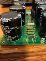
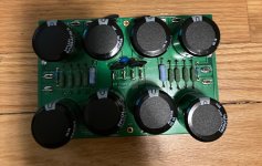
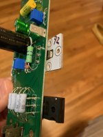
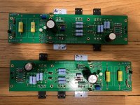
Good source for belts on Pioneer CT91 tape deck
- By profiguy
- Analogue Source
- 9 Replies
My Pioneer CT91 cassette deck needs a fresh set of belts. I haven't purchased any belts recently and would like to find a good source for belts, idlers, pinchrollers and other rubber parts. Many sellers only offer the thicker type belts which won't work. Consistency and quality are another issue. I often have to purchase more than one set of capstan belts to get ones which don't cause excess wow+flutter.
My open reel decks are easier to get rubber drive parts for, but cassette decks are so much harder to service these days due to lack of parts.
Any advice?
My open reel decks are easier to get rubber drive parts for, but cassette decks are so much harder to service these days due to lack of parts.
Any advice?
Beginner's Guide for Building Compact Analog Speaker?
- By Eingrau
- Construction Tips
- 1 Replies
Hi! I'm an Electrical Engineering student looking to build a speaker of similar size to those portable Bluetooth speakers.
While I've taken a few classes on analog electronics, I'm completely new to audio engineering and the audiophile community.
I don't know what kind of speakers would be best, or what would be the best way to physically construct a speaker of this size.
Additionally, what kind of amplifier circuit would be best for this kind of project?
For the amplifier, I really just care about performance (it's going to be plugged in so I don't care about power efficiency).
I also don't want to use tube amps. I know of very basic audio amplifier configurations, but I'm assuming there's better ones out there which is why I'm asking.
I was wondering if anyone knows of any resources that would be helpful for working on a project like this.
Thank you!
Help - New Horn Build Loose Panel, or Some Other Problem
- Subwoofers
- 28 Replies
Hi Folks,
Loose panel? Loose brace? Cone slapping the baffle? Something else entirely? Help!
I recently roughed together a front loaded horn with a rear reflex chamber for a 10 inch Faital woofer I had. This is the second iteration of a design.
Intended use was bass guitar low end (up to 500hz), squeezing as much spl as possible from the woofer I have on hand.
Giving it a test run this afternoon, I was very impressed with the volume, however the longer (and louder) I played, the more I became aware of a horrible raspy/rattling sound.

The sound is much more prevalent at certain frequencies (I initially noticed it at low D on a 5 string bass - ~73hz on the second harmonic where most of its energy is).
I unplugged the bass and hooked up a signal generator to do some more investigating. The noise is occurs most easily at around 115hz, but needs to be fairly loud for it to occur. Once it does, the louder the output, the louder the rattle.
Thinking that maybe the surround of the woofer was slapping against the baffle, I thought I would check the excursion plot in Hornresp. I suspect that this may be part of the answer to my mystery of what has gone wrong, but the plot shows the lowest excursion at around 73hz and 115hz. The diaphragm pressure plot shows peaks at these frequencies too.

Here's a cutaway of the construction, just before I screwed on the final side to complete the box. I used an expanding polyurethane glue and all panels were screwed.

So my question to the brainstrust is what do I do to fix this? I have considered removing the screws from one side and cutting it off with the table saw to expose the inner workings again. I should be able to do it neatly enough that ii can screw another side on without too much hassle.
The raspy rattle seems to sound loudest out of the reflex port, but is also louder on the left hand side than it is on the right hand side. Troubleshooting precisely where the noise is coming from is difficult, because to make it happen, I have to feed the woofer a fair amount of voltage, annoying my wife considerably
If I cut it open, what am I looking for? Is it more likely to be a loose brace than a loose panel? Every panel has two braces on each side, with the braces on different sides offset from each other
I initially thought that the surround or cone of the woofer may be slapping the baffle, but the excursion plot suggests otherwise, and the woofer would need to move well past xlim to get there.
Help would be very much appreciated
Hornresp below

Frequency response for the two iterations of the design below. Plenty of ripple in the response, which is not a problem for this application

Loose panel? Loose brace? Cone slapping the baffle? Something else entirely? Help!
I recently roughed together a front loaded horn with a rear reflex chamber for a 10 inch Faital woofer I had. This is the second iteration of a design.
Intended use was bass guitar low end (up to 500hz), squeezing as much spl as possible from the woofer I have on hand.
Giving it a test run this afternoon, I was very impressed with the volume, however the longer (and louder) I played, the more I became aware of a horrible raspy/rattling sound.
The sound is much more prevalent at certain frequencies (I initially noticed it at low D on a 5 string bass - ~73hz on the second harmonic where most of its energy is).
I unplugged the bass and hooked up a signal generator to do some more investigating. The noise is occurs most easily at around 115hz, but needs to be fairly loud for it to occur. Once it does, the louder the output, the louder the rattle.
Thinking that maybe the surround of the woofer was slapping against the baffle, I thought I would check the excursion plot in Hornresp. I suspect that this may be part of the answer to my mystery of what has gone wrong, but the plot shows the lowest excursion at around 73hz and 115hz. The diaphragm pressure plot shows peaks at these frequencies too.
Here's a cutaway of the construction, just before I screwed on the final side to complete the box. I used an expanding polyurethane glue and all panels were screwed.
So my question to the brainstrust is what do I do to fix this? I have considered removing the screws from one side and cutting it off with the table saw to expose the inner workings again. I should be able to do it neatly enough that ii can screw another side on without too much hassle.
The raspy rattle seems to sound loudest out of the reflex port, but is also louder on the left hand side than it is on the right hand side. Troubleshooting precisely where the noise is coming from is difficult, because to make it happen, I have to feed the woofer a fair amount of voltage, annoying my wife considerably
If I cut it open, what am I looking for? Is it more likely to be a loose brace than a loose panel? Every panel has two braces on each side, with the braces on different sides offset from each other
I initially thought that the surround or cone of the woofer may be slapping the baffle, but the excursion plot suggests otherwise, and the woofer would need to move well past xlim to get there.
Help would be very much appreciated
Hornresp below
Frequency response for the two iterations of the design below. Plenty of ripple in the response, which is not a problem for this application
Jamo Concert 7
I'll be very grateful if someone have crossover schematic for this speaker.Or if can point me to someone who know.
Accuphase C-222 schematics, anyone?
- By seppstefano
- Solid State
- 20 Replies
Hi all,
I'm searching for the schemas of my pre. It recently developped some hum and would like to investigate how2 fix it.
Any help is welcome,
Stefano
I'm searching for the schemas of my pre. It recently developped some hum and would like to investigate how2 fix it.
Any help is welcome,
Stefano
Subwoofer Efficiency
- By nikg736
- Subwoofers
- 26 Replies
I read through most of this thread and saw that it is now closed, but I still have some questions about efficiency.
https://www.diyaudio.com/community/threads/subwoofer-efficiency-is-mostly-irrelevant.358153/
My current application dictates that I have a limited number of watts available (1200RMS) and I am looking to use two 15" drivers. I understand a single driver might suffice, but I am likely going to use these in a home application also.
Anyway, looking at specs, which of the following might lend themselves to delivering the highest SPL yet maintaining decent SQL. If anybody has experience with any of these drivers that would be great. The reason these are on the list is either I have found used examples at a good price or the new units are very reasonably priced. Looking around $200 per 15" driver.
https://www.skaraudio.com/products/evl-15-inch-car-subwoofer?variant=EVL-15 D2
https://www.sonicelectronix.com/ite...xfnrIMS5NUujho2gVtlcGdw3KiZhV01hoCoKkQAvD_BwE
https://www.resilientsounds.com/product-page/gold-15
https://nvx.com/products/vcw154v3-3...JyiufwxvqqR2DCHmPlND4VCTZRk2canRoCug8QAvD_BwE
https://cdn.shopify.com/s/files/1/0655/3550/8703/files/Hawk_Subwoofer.pdf?v=1682346116
Isobaric Single Reflex Bandpass Enclosure (Restore with different design?)
- By bryanlei
- Subwoofers
- 19 Replies
Hello everyone, I'm new here and I have this Dai-ichi ASW-10DR Active subwoofer (chinese brand), it has 2x10" subs in it (clamshell) in a 4th order enclosure, like this;

the box is quite old now and in a bad shape, probably water damaged also (luckily it still works amazingly but do vibrate a lot because the wood is kind of soft now), I would like to re-design the enclosure. Like what I've said, I'm fairly new with bandpass boxes, I do owned few L ported boxes a while back but not a bandpass ones.
I would like to make it a 3 chambered 4th order bandpass like this one;

I kind of know that you do a clamshell design or method to produce twice the power, sadly I do not know the ratings of the subs and I only know the ratings of the amplifier since I look it up in the internet, it's two of these Philips TDA1514A which if I'm not mistaken produce 50w each? So overall knowing it's producing around 50w per sub, it'll produce about a power of a 100w sub right?
so back to the dual 4th order bandpass design, can I make the volume smaller from the original design since I'll have another chamber for the other sub? Let's say the original design has 50 liters of volume in sealed and in ported, can I make the design that I want to 25 liters sealed per sub? and having about the same 50 liters in the ported side? Or am I missing something? Thanks for helping in advance, I would really want to restore the condition of this active sub that I paid for around 10usd only.
I would practically use this for movies and music (assorted genre, doesn't matter if it would not be that so called hi-fi enough since it's a cheapo active sub in the first place).
the box is quite old now and in a bad shape, probably water damaged also (luckily it still works amazingly but do vibrate a lot because the wood is kind of soft now), I would like to re-design the enclosure. Like what I've said, I'm fairly new with bandpass boxes, I do owned few L ported boxes a while back but not a bandpass ones.
I would like to make it a 3 chambered 4th order bandpass like this one;
I kind of know that you do a clamshell design or method to produce twice the power, sadly I do not know the ratings of the subs and I only know the ratings of the amplifier since I look it up in the internet, it's two of these Philips TDA1514A which if I'm not mistaken produce 50w each? So overall knowing it's producing around 50w per sub, it'll produce about a power of a 100w sub right?
so back to the dual 4th order bandpass design, can I make the volume smaller from the original design since I'll have another chamber for the other sub? Let's say the original design has 50 liters of volume in sealed and in ported, can I make the design that I want to 25 liters sealed per sub? and having about the same 50 liters in the ported side? Or am I missing something? Thanks for helping in advance, I would really want to restore the condition of this active sub that I paid for around 10usd only.
I would practically use this for movies and music (assorted genre, doesn't matter if it would not be that so called hi-fi enough since it's a cheapo active sub in the first place).
A question about Focal 6W4359 midbass woofer
I have a pair of Focal Profile 918 speakers.
The midbass woofer is the reference 6W4359.
.jpg")
The bass woofer is the reference 6W4459.
.jpg")
Does anybody know if this midbass woofer (6W4359) is capable of reproducing low-bass frequencies as the other woofer of the speaker (6W4459)?
I found this page on the net where somebody buit a tower speaker by using this same midbass as full range woofer, which gave me the hope that I could use it as such too.
https://www.lautsprechershop.de/hifi/benue_en.htm
Meanwhile, I tried to get an answer to this question directly at Focal in France, but all I got was this reply: contact your local Focal retailer.
It happens that my local Focal retailer doesn't give me an answer.
So it would be great if anybody could answer me this question .
Thanks in advance.
The midbass woofer is the reference 6W4359.
The bass woofer is the reference 6W4459.
Does anybody know if this midbass woofer (6W4359) is capable of reproducing low-bass frequencies as the other woofer of the speaker (6W4459)?
I found this page on the net where somebody buit a tower speaker by using this same midbass as full range woofer, which gave me the hope that I could use it as such too.
https://www.lautsprechershop.de/hifi/benue_en.htm
Meanwhile, I tried to get an answer to this question directly at Focal in France, but all I got was this reply: contact your local Focal retailer.
It happens that my local Focal retailer doesn't give me an answer.
So it would be great if anybody could answer me this question .
Thanks in advance.
Load more
Projects by fanatics, for fanatics
Get answers and advice for everyone wanting to learn the art of audio.
Join the Community
508,488
Members
7,921,709
Messages