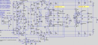
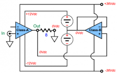
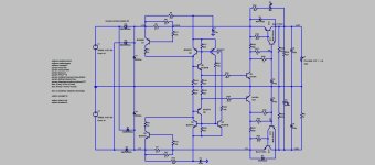
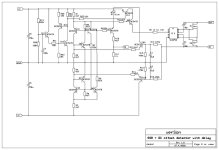
This amplifier I built two year ago. It is Class A OPS bootstrapped by Class B.
It uses my OITPC compensation and it needs low voltage floating power supply for the Class A OPS.
It uses my OITPC compensation and it needs low voltage floating power supply for the Class A OPS.
Attachments
-
 100W CFA ClassA+ClassB .sch.jpg154.2 KB · Views: 899
 -
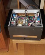 100W CFA ClassA+ClassB in play2.jpg270.3 KB · Views: 842
 -
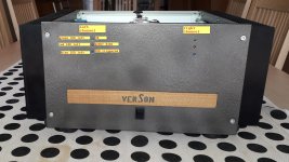
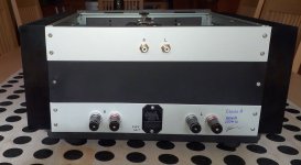 100W CFA ClassA+ClassB back.jpg188.1 KB · Views: 473
 -
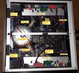 100W CFA ClassA+ClassB 4.jpg642.7 KB · Views: 413
 -
 100W CFA ClassA+ClassB front.jpg304.6 KB · Views: 425
 -
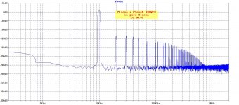
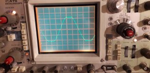 100W CFA ClassA+ClassB clipping.jpg207.1 KB · Views: 426
 -
 100W CFA ClassA+ClassB-SMica- THD1.jpg89.6 KB · Views: 421
 -
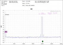 100W CFA ClassA+ClassB IMD.jpg82.1 KB · Views: 829

Some more information about a design process I took some years ago.
If someone interested in this amp I have two spare boards.
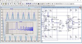
1. Shows the Loop Gain plot
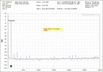
2. FFT at 10kHz on 2W/4R
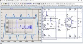
3. 100W/8R
4. 200W/4R
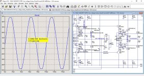
5. 130W/8R before clipping
By the way Class A OPS bias current is set to 2.5A
Damir
If someone interested in this amp I have two spare boards.
1. Shows the Loop Gain plot
2. FFT at 10kHz on 2W/4R
3. 100W/8R
4. 200W/4R
5. 130W/8R before clipping
By the way Class A OPS bias current is set to 2.5A
Damir
Attachments
-
 130W CFA ClassA_ClassB-FFT10k_2W_4.jpg158.1 KB · Views: 207
 -
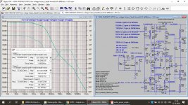 OITPC-LG no dc offset at input.jpg275.5 KB · Views: 221
 -
 100W CFA ClassA+ClassB 100W_8R-sim.jpg217.3 KB · Views: 214
 -
 100W CFA ClassA+ClassB 200W_4R-sim.jpg205 KB · Views: 193
 -
 100W CFA ClassA+ClassB 130W_8R-before clipping.jpg188.9 KB · Views: 201
This is a form of class H with floating supplies instead of fixed supplies with series diodes. The things I would watch out for are:
Ed
- Floating supplies can couple supply noise into the signal since "floating" precludes filtering with respect to ground.
- The class A amplifier needs good supply rejection to avoid passing through the class B non-linearity.
Ed
This floating supply is connected to the ground via ClassB OPS.
My intention was not to get better effciencies only, as the the efficiencies of this amp is close to ClassB efficiencies but with sound quality of a ClassA amp with ClassB efficiencies.
I don't think is over complicated, simmilar to my ClassB CFA amps with just two different OPSes, low voltage ClassA and high voltage ClassB.
Dear Dadod,
You sparked inspiration to start a similar project for a school assignment. We will try and build a class A with tracking supplies for Analog Design.
A couple questions:
-does your class B stage have bias?
-your class A stage runs at 8V with 1.75Amp per mosfet?
-We're noticing how the class B bias and output impedance affects global Gain and phase margins quite dramatically. Is it true that such arrangement need more compensation?
I would love to share our design with you. May I pm it to you?
Much thanks and cheers,
Ruben
Hi Ruben,
You can unzip the file in post #7 in the same folder and simulate it in LTspice. There are all needed files.
In post #4 you can see the values of the Class A and Class B OPSs, 2.5 A and 81 mA. That was as I simulated it.
Class A can run on +-7 V or more (with more power dissipation).
Good luck with design, a layout is equally important as the circuit, and yes you can PM to me.
BR Damir
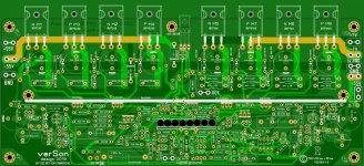
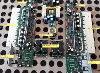
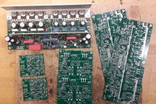
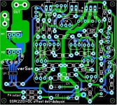
From this project there left some spare boards and if someone interested to build this amplifier I can offer a set for one amplifier.
The set contains two main amplifier boards, two low voltage power boards(capacitor multiplier type) with overcurrent protection and two SSR(solid state relay) with delay on switch on.
The price for the set is 100 EUR plus shipping.
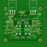
Finished main amplifier board is an example how t looks.
The set contains two main amplifier boards, two low voltage power boards(capacitor multiplier type) with overcurrent protection and two SSR(solid state relay) with delay on switch on.
The price for the set is 100 EUR plus shipping.
Finished main amplifier board is an example how t looks.
Attachments
- Home
- Amplifiers
- Solid State
- 100W CFA Class H (ClassA + ClassB)