MB QUART ONX1.2000D protect cycle

Hey guys got an MB quart onx1.2000D

Cycles power and protect.

Chips on power supply board have been shaved. Does anyone know what they may be using here? So I can pull up a datasheet and check appropriate voltages.

No shorted fets in power supply or output section.

powers up and does start switching on all power supply and output fets (not the cleanest looking though) for about half a second before going back into protect and starting all over again.

seems to have all plus and minus voltages present for a fraction of a second.

Cheers
20231108_120450.jpg
20231108_120500.jpg
20231108_120510.jpg

A tale about non-constant directivity waveguide and horns

This thread has the purpose to investigate non-constant directivity waveguide and horns.

I got interested since it is inevitable to avoid the transition from high directivity at high frequencies to omni-directional at low frequencies. I wish for this to happen over a large frequency range to avoid any abrupt change in directivity.

Much has been done on constant directivity waveguide and horns, so I thought to explore the opposite. Some has been done in this area too, but I'm curious to find out how it sounds like.

Take 1
A slightly modified Kugelwellen horn. It starts at 70 degrees and the overall all curvature is stretched to get a bit more in the wg and less back-fold. I did the calculations some 10 years ago (before kids, 3D-printing and the genius tool ATH was available).

Print is 30 cm wide.
DSC_4509.JPG


DSC_4511.JPG

DSC_4520.JPG

DSC_4517.JPG

DSC_4519.JPG


Was also 10 years I did some measurements...need to freshen up...

TU-8500 phono stage upgrades

I've really gotten the vinyl bug again after finding several large boxes of LPs that I forgot I had, mostly from the 70's. I really am enjoying my 8500 with 8200, always looking for possible improvements. What phono stage upgrades can I make to get even more from the 8500, I love to tweak...Thanks
The 8500 is stock except for the tubes, I'm running Sylvania 12AT7 JAN

Third-wave pipe speaker

The following is from a tntaudio review. I would be interested in opinions.

The smaller Kerr K300 utilise a short transmission line (as in the Bailey approach to minimise overhang and dissipate cone rear energy. The larger Kerr Acoustic K320 uses a hybrid of transmission line and tuned third wave pipe. The familiar Tuned Quarter Wave Pipe (TQWP, often mis-described as a transmission line) has some of the power handling advantages of reflex loading (controlling cone excursion near the system resonant frequency) but fewer group delay disadvantages than reflex. This results in lighter but faster sounding bass and more placement flexibility in the room. The tuned third wave pipe trades some of that excursion limiting advantage in exchange for even lower Q bass tuning knee and deeper (quasi second order slope over 1 octave) extension.

Various stuff free or for sale

I need to clean my place. I am sure we all get that urge from time to time. Honestly, I accumulated too much stuff and instead throwing it away, I will post it here and see if there is interest. Most for free, some for sale, to recover some material purchased.
All I ask if you pay shipping, small flat rate box is ~$11, medium is $17 and large is $23. I will just estimate if it fits.


Update: all attenuators are spoken for.
B1 is spoken for.
Realistic headphones are spoken for.


Now we have second round for Shure riaa.
Added metal hole punching tool for you tube guys and small balancing transformers.
Added thick 12 gauge speaker wires.

JLH ClassA amp and lm1875 boards are gone.
  • Like
Reactions: Bigman80

Class D amplifier problem (HK Audio pro 18 subwoofer)

Dear all,

I have an issue with my build in class D amp in a HK Audio Pro 18 subwoofer.

I have 1 in working order, and 1 is faulty.

What happens is the following:

-If you turn it on, it starts to hiss
-if you play music it is significantly less loud then the one that works.
-after 5 minutes, it makes 1 loud pop then makes a very loud screeching sound and then the red light goes to red meaning ERROR.


Does anybody know what I could do or check to see if some components are broken! I personally think it is the power module or a MOSFET?

Attachments

  • 1538998956_MG_8610.jpeg
    1538998956_MG_8610.jpeg
    17.8 KB · Views: 122
  • 53974_photo.jpg
    53974_photo.jpg
    31.1 KB · Views: 102

Speaker design to carry on a camel, considering Karlsonator

Alright here's the quick and dirty. I've been living with a group of animals (goats, sheep, yaks, and camels) for a number of years now, doing long multi month trips on the trail with them. Starting to get spoiled and wanted to have a throw back to the days where I could listen to music on something other than a cell phone. I need a speaker that is light, size is less of an issue with packing on a camel, and I can always use it as a stool or even have a removable side to use it for storage on the move. But still not much bigger than 20x15x15. I am thinking a mono setup, paired with a high efficiency amplifier that I can power off the 12v battery/100w solar setup I have with me. It will be used outside or in a tent, and will be protected from the weather when necessary.

Pitch me some ideas if you got anything good (or a used amp or driver that you want to sell : ), and I promise to post some pics as this develops. Right now I'm leaning towards some type of class D amp with a .53 Karlsonator, although I'm trying to find a speaker with a neo magnet that could work in this design. Thanks in advance for all the feedback, good to see the forum again!

Chris

Attachments

  • yakspack.jpg
    yakspack.jpg
    98.9 KB · Views: 136
  • Like
Reactions: Arez and Fuling

For Sale Tested Audio Tubes

All tested with my trusty low mileage calibrated TV2 tester.

19 test good 6V6GT. One RCA 6V6GT/G, five RCA 6V6GT (most smoke glass),one RCA 6V6GTA. One Sylvania 6V6GT/G, five Sylvania 6V6GT. Two Ken Rad 6V6GT/G. One CBS 6V6GT. One NU 6V6GT/G. One GE 6V6GT/G, one GE 6V6GT. All $100.

Octet of test NOS close Sovtek 6922 (6DJ8): V1 100,102; V2 102,104; V3 107,115; V4 110,110; V5 102,102; V6 104,105; V7 97,100; V8 103,103 min is 65. All for $100


National 5751 USA 72,70/64 $20


Rare GE 5 star 6189 12AU7WA, s rods 85,85/72 $40.


CBS short black plate 12AU7A 87,90/72 $30.


NOS RCA 12AU7A black plate 85,94/72 $20.


JAN 5U4G RCA match test NOS 105,106/75 $45.


Five Sylvania 5U4GB black ribbed plate top getter test NOS and balanced $50/all.
Will bargain for multiple purchases.

+ ship zelle ppff

Attachments

  • 094D55FC-87C8-4877-86C8-45DFC99D53BF.jpeg
    094D55FC-87C8-4877-86C8-45DFC99D53BF.jpeg
    971.7 KB · Views: 61
  • 3EE518EE-95CF-4B95-9F13-B412E7B2F2C8.jpeg
    3EE518EE-95CF-4B95-9F13-B412E7B2F2C8.jpeg
    901.5 KB · Views: 59
  • 1A63B284-00D9-4D85-B58C-5AF6A4AC389B.jpeg
    1A63B284-00D9-4D85-B58C-5AF6A4AC389B.jpeg
    981.8 KB · Views: 65
  • F1C98D17-3C0C-4875-84B1-B4CD014AC6AA.jpeg
    F1C98D17-3C0C-4875-84B1-B4CD014AC6AA.jpeg
    863.7 KB · Views: 54
  • 7524B6EA-9430-4DAD-A42D-557110812C96.jpeg
    7524B6EA-9430-4DAD-A42D-557110812C96.jpeg
    977.1 KB · Views: 64
  • 5CFA1EFD-834C-47A3-9155-5CFC5161F9BA.jpeg
    5CFA1EFD-834C-47A3-9155-5CFC5161F9BA.jpeg
    861.5 KB · Views: 58
  • 1629C1F4-FA6A-4EF2-8F03-0AA0ADC5D4F5.jpeg
    1629C1F4-FA6A-4EF2-8F03-0AA0ADC5D4F5.jpeg
    762.2 KB · Views: 60
  • 87B53D71-2AB4-4B43-80A2-3B4991FB6126.jpeg
    87B53D71-2AB4-4B43-80A2-3B4991FB6126.jpeg
    492.6 KB · Views: 44

For Sale Hashimoto Iron H-20-7U + C-15-200C + PT-160R + A-105

As it seems I will not be able to finish my 2a3 SET amplifier project due to lack of time, I am selling my Hashimoto iron. All components are in excellent optical condition. Have been running few tens of hours (max. 30h) in a prototype. Coming with original boxes.
  • H-20-7U output transformer pair: 550€
  • PT-160R power transformer (230VAC input): 280€
  • C-15-200CH choke: 250€
  • A-105 interstage transformer pair: 350€
Shipping from Germany within Europe possible.

Attachments

  • A-105_1.jpeg
    A-105_1.jpeg
    397.6 KB · Views: 128
  • A-105_2.jpeg
    A-105_2.jpeg
    305 KB · Views: 118
  • C-15-200H_1.jpeg
    C-15-200H_1.jpeg
    317.6 KB · Views: 118
  • C-15-200H_2.jpeg
    C-15-200H_2.jpeg
    190.7 KB · Views: 130
  • H-20-7U_1.jpeg
    H-20-7U_1.jpeg
    406 KB · Views: 124
  • H-20-7U_2.jpeg
    H-20-7U_2.jpeg
    314.2 KB · Views: 122
  • PT-160R_1.jpeg
    PT-160R_1.jpeg
    298.2 KB · Views: 123
  • PT-160R_3.jpeg
    PT-160R_3.jpeg
    231.6 KB · Views: 123

Dared MC-7P Blown resistors help

Hi,

My Dared MC-7P started making a strange hum. I tried testing and replacing all the tubes, but that didn't work. I opened it up and found two blown resistors, R35 and R36. Now that they are burnt I can no longer read the color coding. Does anyone know what the value of these two resistors is based on a schematic or by looking at your own unit? I can't find a schematic anywhere online and I can't be sure of the values based on any of the photos others have shared of the inside of the unit.

Also, if anyone has thoughts on why these two resistors blew, I'm open to ideas. Without the schematic, I'm not sure of where they sit in the signal path.

You can clearly see the blown resistors in the photo.

Thanks for any and all help.
Jeremy


PXL_20231030_172331602.jpg

ES9018K2M, ES9028Q2M, 9038Q2M DSD/I2S DAC HATs for Raspberry Pi

Since I’ve already made Raspberry Pi capable for DSD playback, I think I’ll need a DSD/I2S DAC HAT for it. Few DSD DAC is available for Pi so far, so I’m gonna design something around.

I’ll pick up ES9018K2M first because basically it’s the 2 channel version of ES9018 (2ch vs 8ch), and I've been very happy with ES9018. Both of them have same SABRE32 Reference DAC core, so good sound quality is expected, here are some speciations:

. Industry’s highest performance 32-bit mobile audio DAC with unprecedented dynamic range and ultra low distortion;
. Supports both synchronous and ASRC (asynchronous sample rate converter) modes;
. Unmatched audio clarity free from input clock jitter;
. 127dB DNR -120dB THD+N;
. PCM384KHz/DSD512;
. Mono or stereo output in current or voltage mode based on performance criterion;
. Supports SPDIF, PCM (I2S, LJ 16-32-bit) or DSD input;
. 64-bit accumulator and 32-bit processing. Distortion free volume control;
. I2C based software control;

Prototype PCB is coming very soon.


ES9018K2MPiPCB
by Ian


ES9028Q2MDAC3
by Ian, on Flickr


ES9038Q2MRaspberryPiDAC
by Ian, on Flickr

Ian

Bang&Olufsen Beo4 remote fixing, help needed for parts

Hello everyone,

I'm trying to fix a Beo4 remote control which doesn't work anymore, no beam. It's for an old lady who doesn't move easily and her remote is important to her.

I opened it, and I saw quickly that the little CMS fuse is blown. On the picture it is blue circled, located between the 74HC393 binary counter (pin 1 if I'm right) and the other IC for which I can't find the type (a kind of EEPROM?). That fuse is marked 1.82 d and is a 7x2.5mm sized component. Would that be 1.82A? not a common value for a fuse. I'd like 1) to find an equivalent 2) before I replace it, have a test made with an external fuse could be useful. Could I try with a 1.5A, or a 2A? fast, slow-blow?

Beside that, as one says, if the fuse has blown, there's maybe a reason (or not!)... I'm not SMD fluent, so I couldn't figure out what this little component circled in red that looks like a diode... but as it is really dark brown, I can't say even with the binoculars if I see a kind of cathode marking on it. With the Fluke I can read 0,6V in one way and OL the other way, so I guess it is OK and tells me about the anode/cathode position. Does someone confirm that it is or could be a diode, like from a SOD series? It seems there is another one nearer to the battery supply which reads OL/0.24V which could name a shottky diode? The only thing I can say is that it is a 4,5V powered remote. All resistors beside are in the specs (easy to read) and the caps show "normal" values.

There was some glue leaking from the adhesive tapes between the 2 electrolytics on the PCB, I cleaned it thoroughly. As I know that it can sometimes make unwanted contacts, could it be enough to have this remote fail? Can't say...

If I solder in place with 2 wires an external fuse which can blow without making any trouble to the PCB, maybe I would be able to trace the voltages to the ICs and see if something else is in bad condition?

Ready to read from experts! 🙏 Thanks

Beo4 PCB detail.png


Close shot of the fuse:

fuse Beo4.png

For Sale Pair of Altec 803a 15” 16 ohm alnico woofers from 1956.

Lots of details on the web on these fabulous speakers, including on a pair just like these on hifitown here: https://www.hifitown.com/index.php?dispatch=products.view&product_id=29945

This pair are all original (clamped, 20409 stamped cones with treated paper surrounds etc).

Both measure 8.1 ohm DCR and play wonderfully with no buzzes, scrapes etc. In amazing condition given their 65+ year age.

Only blemish is that they both got some light paint spatters on the cones somewhere along the way and are a bit dusty. See pics.

Would make an awesome pairing with my some of other gear for sale (e.g. RCA MI 9458 or Renkus Heinz SSD 5600 drivers). Just add a (very) large horn (e.g. SATO) and some tweeters.

I’m based in Dublin and cash-on-collection most welcome, but happy to ship (preferably UK/EU) at buyer’s expense and risk.

Asking €1600 and payment via bank transfer or paypal friends/gift.

PM for further pics/details etc.

Cheers
Adrian

Yukon Gold - a spud amp

I’ve never made a Spud amp. This thread is to chronicle my adventures making a single-ended Spud amp. That’s just one tube(er). And perhaps the purist approach is a tube with only one vacuum device inside. So the 6BM8 is out of the running.

What started me off was a friend offering me a Hammond 125ESE output transformer in return for a nice burger. This OPT has a lot of flexibility. And so I’ve bolted it down onto my universal test rig.

-------

6E5P: the basis for the first version of this amplifier is a neat little Tetrode. It's a lively tube that punches above it's weight, however the smoothest sound comes from Triode operation.

6p15p: this is a true Pentode and the approach being considered is in schematic in post 22 and discussion starting post 65

Attachments

  • test rig.JPG
    test rig.JPG
    515.3 KB · Views: 2,601
  • potatoes-boile-yukon-gold.jpg
    potatoes-boile-yukon-gold.jpg
    153.2 KB · Views: 2,530

200W IRS2092 Amp for $20

This was moved over from the TDA7492 thread since it was off topic.
********

A little OT, but wanted to let you guys see what just came in the mail from Aliexpress...

These things are pretty compact - a little smaller than YJ blue/black 3116.

Very nicely made, appear to be quality components and very clean soldering work - IRS2092 200w monoblocks for $19ea shipping included. I am using qnty 4 x 19v laptop smps bricks in series for +/-38v supply (4.6amp limited) as the power supply. Testes it with some PA drivers and it is loud and clean. A great deal - easy to hook up and use - just need dual rail supply is the only downside. I may have to buy a Connexelectronic dual rail SMPS for $50 to get the real juice.

Recent price drop now $16 😀

http://www.aliexpress.com/item/IRS2092-200W-Class-D-mono-amplifier-board/32257919878.html

488239d1434199057-10f-8424-rs225-8-fast-ref-monitor-irs2092-monoblocks.jpg


Update (June 19, 2015): I testes this with the $20 Abletec dual rail 53v power supply and it works very well. Clean and loud.
http://www.diyaudio.com/wiki/TPA3116D2_Boards

Test setup:
489453d1434791767-200w-irs2092-amp-20-irs2092-amp-build.png

Heater-Cathode Voltage

Hello all,

This is my first post, although I've been a member now for a while. As a hobby,I've been studying "electronics" and "tube electronics" for a couple of years now. My goal is to be able to design and build great sounding components for my enjoyment and that of my family and friends. I am still far from my goal. I'm afraid I'm seriously mathematically disinclined, and I'm really stubborn about asking for help.

I've recently built Fred Nachbaur's phono-pre and I've just finished "Frank's 6SN7" line level pre. Both of these were built with about 97% salvage materials, in the interest of minimizing the cost of learning. I did make a walnut and aluminum chassis for the new pre though.

Since Frank's pre schematic doesn't really include a power supply, I'm a little concerned about the heater-cathode voltage since I cobbled together the power supply from on-hand components.

I've searched high and low, and maybe I'm not using good search terms, but I can't find a direct description of how to measure "heater cathode voltage". I mean, seemingly all tubes have a maximum "heater-cathode voltage" which may be X volts positive or negative. Everybody must already know how to measure this or else there would be some better references on the web. I however, do not.

Would someone please point me to a reference of how to measure this parameter or provide their own description?

Thanks.

Marantz PM7200 Protection mode

Hi,

My 7200 goes into protection. The symptoms are; upon initial switch on from cold the amp plays happily for a few minutes then a thud is heard through both speakers and goes into standby. If the amp is left for 5 or 10 minutes it will switch itself back on for a few seconds then cut out again until it won’t do anything unless powered down overnight.

Having researched known issues for the 7200 it seemed likely the capacitors are failing after many years of use. So I’ve changed all caps on the protection board and all the caps on the power supply board but the issue remains. All the boards have been flexed while powered up and a dry joint hasn’t shown up.

Any ideas to move forward appreciated.

David.

Better classic transformer o switching power supply for LM3886 ACA?

Hi all,
needing dual power supply, it would be better:
a) dual trafo/rectify/capacity section
b) a single transformer/diodes/caps
c) single trafo, dual center-joint coils, dual diode-bridge, dual caps
d) single trafo, dual separated coils, dual diode-bridge, dual caps; 0V (PGnd) node realized on DC line (V1- to V2+
e) two AC-DC Switching board providing needed voltage V++/V-- ; 0V (PGnd) node realized on DC line (V1- to V2+
f) four AC-DC switching boards connectet series-parallel in order to get needed voltage (ec. 24v+24v series modules each block jointed to get 48V++ and 48V--
I've recently found some stick bars of some LM3886 and LM4780 forgotten on stock 20years ago and now I would like to bild a good ACA, the best I can.

I've already tried to build a LM4780 based CAC prototype using two 19,5V notebook power supply, but is a little bit noisly when music silence
No humm comes when supply is from transformer/rectifier/ripple filter stage

Looking for Accuphase P-300L Service Manual and schematic

Good day fellow DIY'ers,

I recently imported a Accuphase P-300L from Japan to join my small and humble Japanese vintage audio gear collection. I'm planning to use it as daily driver next to my Sony TA-N7B which I'm currently restoring from the ground up. Both connected to a restored C-222 pre-amp, but eventually to a C-200L pre-amp.

The P-300L is in excellent condition. Everything seems to work fine and it is completely stock and untouched. I already rewired the transformer wires to make it work on 240V. The option to do so on almost every Accuphase unit is fantastic. No more AC converters, at least not for this unit ;-)

As usual with Accuphase units from this era, they used top notch component. Lots of PP and even mica caps.

Although the unit works fine, I want to make it more future proof. Not a ground up restoration like I mostly do, but only replace parts which can cause trouble in the future.

Work to be done:
  • Replace all 'lytics.
  • Check and test the specs of the main filter capacitors. If not up to spec -> look for replacement (not easy with these dimensions.
  • Fresh thermal paste on the output transistors (or AAVID sil pads?).
  • Replace bias trimmers (known for taking out output transistors when they fail).
  • Check and test zener diodes, replace when out of spec.
  • Place fuses in the yellow wires from the transformer.
  • Replace all relays.
  • Replace speaker terminals on the with ones which accept banana plugs.
  • Clean all switches.
  • Maybe check the fusible resitors?
  • Adjust everything to the specs of the manufacturer.
To me it seems that the VU meters of the P-300L move to little to the right. At moderate listening levels they barely move. When I compare it to my Yamaha B-2 (comparable scale), of which the VU meters move a lot more at the same listening levels. I would love to adjust the VU meters to SM specs. There are 4 trimpots on the VU meter board for adjustment.

I looked on all known websites and forums for a Service Manual and a schematic, but no luck. I found one thread on DIY Audio where a fellow member claims that the problem of him searching for a P-300L SM / schematic is 'solved'. But not sure the member didn't need it anymore or he found it. Anyway, I do not have posted enough, so I can't send a PM to this specific member.

All help is welcome!

I will post some pictures of the Accuphase later on. I'm struggling with the new HEIC format of pictures that Apple uses in iCloud.

TL072 / OPA2134 in 2 way crossover

Hi, I have got a oem printcard from the Norwegian "Embla" crossover designed by Tom Helgesen. He is an ex Tandberg designer, made there cd player and moore.

He used the TL072CP for the filter, I have spoken to him and he say I may try the OPA2134 as they are also FET.

Im gone use only the lowpass unit on the filter but build it as a complete filter.

For high freq the OPA2134 is suppose to beat the TL072 in performance, I have read ( :

Go for TL072 or OPA2134?

Frank
IMG_2588.jpg
IMG_2590.jpg
IMG_2591.jpg
IMG_2592.jpg
IMG_2593.jpg

DC voltage on Triode grid

I'm working on an amp which has 2 X cathode biased EL34's and a pair of 6N2P's in the input stage and phase splitter stages.
Originally it had an ECC81 and ECC82, one of these was dead so I replaced both with the 6N2P's.

Doing some testing I've noticed around 16v VDC on pin 2 of the phase splitter. I replaced the 0.22 blocking capacitor suspecting this may be the issue but the problem persists.

There's a grid resistor 1.16M which goes to a tag which is shared with the cathode resistor from pin 3, then a 22.6K to ground.

I've tested continuity from pin 2 to ground to make sure the grid resistors have a path to ground which they do.

As a newcomer to this I am unsure how to proceed.
Hope someone might be able to shed some light.

Regards 👍

Celebrity Speakers

Henry Rollins is just about the only musician I'm aware of who has "audiophile" speakers.

I noticed in an online article about Alicia Keys that she has Beolab 90s.

If you're ever in San Diego, the B&O store is less than ten minutes from their house, in La Jolla. I used to live in the area and have been in there a few times. Nice shop.

Here's some pics of the house, it's quite a place:

2023-11-02 13_59_39-alicia keys la jolla house - Google Search.jpg


razor-house-20-e1635965860746.jpg


altman-razor-home-sale-01.jpg

Attachments

  • 2023-11-02 13_53_52-Inside Alicia Keys and Swizz Beatz’s Art-Filled Modernist Home Overlooking...jpg
    2023-11-02 13_53_52-Inside Alicia Keys and Swizz Beatz’s Art-Filled Modernist Home Overlooking...jpg
    169.2 KB · Views: 732
  • Like
  • Thank You
Reactions: el156se and GM

TPA3116D2 Power Supply

I've used this board in a number of projects. The 2.1 claims 100w + 50w x2. So far I've been using a 19.4V (130 watt) laptop brick for power - 19.4V doesn't max the output but it does a job. Because I like recycling and I NEED to LEARN I've wondering if I can build a rudimentary out of the crap in my junk box.
I have a transformer from a BOSE Companion Series 5 - 18.5v (26v). BOSE claim the system is 300w but I'm guessing it's maybe 80-100VA?

I have a LVA10433 board from a JVC System.

Can I salvage enough parts to make rudimentary power supply?

JVCPSU1.jpg

Attachments

  • JVCPSU2.jpg
    JVCPSU2.jpg
    93.9 KB · Views: 80
  • JVCPSU3.jpg
    JVCPSU3.jpg
    72.2 KB · Views: 82
  • LVA10433.PNG
    LVA10433.PNG
    37.3 KB · Views: 83

Why is flat not flat - On my setup

Two doubts in my mind.
1. We use a calibrated mic to get a flat output from two drivers one is a woofer and the other is a CD. The Umik-1 says the SPL is the same on both. A lot of time and effort went into achieving this. But... the CD seems to over power the woofer when listening to music. I had to dial back the CD by about -6 DB on the SPL meter to make it sound right. Is this normal / desireable / or Im just an idiot who has made a basic mistake.
2. I have a full range 8 inch that when added to the 15 inch woofer and the CD sounds amazing. My only problem is the woofer is 300 watts the CD is 80 watts RMS. And the 8 inch I want to add is only rated to 20 watts. How do I safeguard my 8 inch driver should somebody crank the music up. I know adding a L pad or resistors would limit the power going to this driver. But it also reduces its output to a point where it can no longer be heard. Am I missing something. Or is the only solution to buy a 80 watt full range. ?.

PSUD: Voltage Drop on added filter section

Hello !

Looking at powering a tube filament via regulator I tried single section LC as well as LCRC. The filament is 4V/1.1A and the filament regulator is constant current with operating voltage of 3V expected, for a total of 7VDC.

I did the simulations with both CCS and also with an equivalent resistor (7V/1.1A=6.36Ω).

Both gave drop across the second section's 0.1Ω resistance much greater than I'd thought were realistic , near 3V in the case of the resistive load and 5 volts in the case of the CCS. Even at 10 times a simple IR drop it would only be 1V.

Surely the results can't be quite right, or can they?

Thanks

Attachments

  • LC Resistive Load.png
    LC Resistive Load.png
    21.4 KB · Views: 82
  • LCRC Resistive Load.png
    LCRC Resistive Load.png
    27.6 KB · Views: 83
  • LC CCS Load.png
    LC CCS Load.png
    19.7 KB · Views: 83
  • LCRC CCS Load.png
    LCRC CCS Load.png
    25.2 KB · Views: 81

What to use as connectors with Intertechnik crossover development boards?

I have some Intertechnik crossover development boards. These have 2mm through holes, copper plated pads, and the holes are rather wide apart.

I have a preference for soldering on something with a crimp tag or a screw terminal, but I'm not finding anything.
Maybe I'm not using quite the right search term - 'pcb screw terminal' doesn't find me singles, just terminals with two or more screws, albeit some variations of spacing.

Any suggestions?

Very different measuring T35's on the middle of recap...

I recapped one Wolverine LT-12 with two 1.5 parallel films and .47ohm series. The tweeter measured 8.7ohm, seemed normal.

I start on the second speaker and wide open I'm getting 12ohms?

First speaker on "flat" measured around 6 ohms with the woofer. I don't want to reopen it if I don't need to, it seems like it's the normal one?

Despite reputation the LT-12 is a really nice 2 way driver I think. I'd like to have them both in order but noticed if you loosen the nut on the T35, the felt is glued to it so you can't just pull it out. Also read that hardly anyone can center the diaphragms even in free floating T35 tweeters.

Sigh, not sure here? Getting the feeling that you buy lots of LT-12's and try to put together a matching pair you can recap? (that won't happen)

Burning Transistors and lessons learned

So the other day I blew pretty much all the transistors in my amp with my butter fingers. The one time I decide to set the bias without the safety lamp and I short the rails. lol.
So I had the amp up and running in 30 min. But also had a lot of failed transistors. So I thought lets expose the internals and take some macros shots.
I started with my CDIL large drivers. These were hard to open up. Even putting them on the gas stove did not soften the epoxy. But after doing this I moved onto doing the CDIL BD139 / BD140. This time I found the transistors instantly lit up like camphor balls.
The epoxy was highly inflammable. And once burnt out the epoxy just fell away like dust.

Ive seen hundreds of posts on testing transistors but not once have i read of people talking about analyzing the epoxy used.
I find it strange that a company like CDIL would have two types of epoxy in use. And what their logic would be for this.
Its more likely that the BDs were fake. But all of them worked fine. They were all pushed hard and tested on the scope.
Food for thought the next time you blow a transistor and want to see what's inside.
I use a special brand of araldite Highly dielectric epoxy CY205 mixed with powered glass. There is no way in hell I would randomly change the epoxy I have been using for years.
If you do decide to try what I just did. Be safe some of these light up like petrol. Some explode some pop.

Excessive cone excursion - winisd help

Hi everyone. Bit of a hifi novice trying to learn here.
Currently trying to design a MTM 2 way enclosure and I’m running into some issues with cone excursion and I just need some advice as to what to do.

I have 2 Dayton audio RS150p-4a woofers per cabinet that I plan to run in series and a Dayton audio DC28F-8 tweeter.
My friend advised that I should get an amplifier which can supply a little more power than the sum of the power rms values of all the drivers so I picked up a second hand NAD c372.
I’m now running into some issues in winisd where when I enter a higher signal value I’m getting excessive cone excursion at around 80Hz.
One of the ways I’ve seen you can manage this is a high pass filter. My question is wether this is the correct thing to look into doing and wether this goes into the crossover design or preamp stage?

Any help is appreciated

Rotel RA1592 flashing power button

Been having a really bad experience with rotel products, expensive, gorgeous, high quality pieces of junk, just about every piece (new units ) fail... current issue, ra1592, adjusted a few settings in the menu, then powered off, on restart blue ring around power button just steady flashing and clicking, lightly used mint unit out of warranty, which means support or repair is all but impossible... if anyone knows the flashing code or how to hard reset a unit not using menu option, that would great, or a qualified repair center near Nashville.... I could use your help....

Duo Vac, New Chinese tube tester?

With all the crap going on in the vacuum tube world I thought I'd look into the possibility of starting to test several large boxes of tubes I've collected over the years. I've been intrigued by the latest type of tube testers like the MaxiMatcher that used short pulses at operating voltages that are supposed to give better results than the older style testers. I mean, they sound good and several folks that I know swear by them.
Ok, so I decide to search Ebay for tube testers just to see if anything new has cropped up, suspecting that the Chinese might have copied the design by now. Well, this looks pretty similar, looks like they pulse the tube with high voltage as well and give you a digital readout. All for $320.00!
Does anyone have any experience with one of these?
https://www.ebay.com/itm/1538982236...k06K85RrFv6cohdj|clp:2334524|tkp:BFBMhuLk2vJf

BillWojo

Suspicious Tx measurements – need insights

Context: I've been troubleshooting a persistent biasing issue of my DIY Class A/B amplifier. The amplifier bias drifted to infinity or 0 when using linear transformer-based double mono PSUs. The same amp biased as expected when I switched to SMPS modules, which led me to believe that the problem may lie with linear power supplies. After some examination and testing, I suspect that one of the two transformers can be malfunctioning. Any insight or suggestions for additional tests would be greatly appreciated.

Transformers: For the measurements only one transformer was connected each time. One primary connected to Neutral (N) and the other to Line (L), with the "0" connected to the chassis ground and power Earth. Please see the attached picture for transformer specifications and wires. Transformer #1 and Transformer #2 are supposed to be closely identical in specs, but their measurements suggest otherwise.

Measurements between secondaries with DMM:


Tx#1


Blue1 Blue2 26.41V
Blue 1 Black1 0.48V
Blue1 Black2 26.5V
Blue 2 Black1 25.7V
Blue2 Black2 0.3V
Black 1 Black2 26.7V


Tx#2

Blue1 Blue2 26.7V
Blue1 Black1 4.17V
Blue1 Black2 21.6V
Blue2 Black1 30.2V
Blue2 Black2 4.5V
Black1 Black2 26.5V

Measurements of secondaries in reference to 0:

Tx#1

Blue1 17.7V
Blue2 8.2V
Black1 16.9 V
Black2 8.3V

Tx#2

Blue1 144.2V
Blue2 170 V
Black1 137.2V
Black2 162V

Measurements of secondaries in reference to 0 with flipped phase (reversed the plug):

Tx#1

Blue1 17.4V
Blue2 8.3V
Black1 16.6V
Black2 8.6

Tx#2

Blue1 51.3V
Blue2 27.4 V
Black1 49.2 V
Black2 25.7

The discrepancies in readings are suspicious and alarming, that's why I came here to ask for any insights into potential causes or further diagnostic steps. Thank you for looking into it.

Attachments

  • 1.jpg
    1.jpg
    244.3 KB · Views: 61

feature request: make diyAudio better by creating the ability for a user to "hide" threads

When I see pointless or useless or inane threads pop up on DIYaudio I crave a feature that is sort of the opposite of "watch thread". Enabling this feature would hide the entire thread from the DIYaudio thread list for any particular user who is logged in to the forum.

MODs, please please please consider creating this as a new and useful feature of the forum.
  • Like
Reactions: petoluk

Super simple heater/filament and HT/B+ switcher

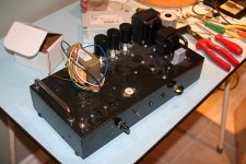
I was tinkering the other day for a simple solution for a project with a DC filament/heater power supply.

These days I often like to use these small DC SMPS power supply (from Meanwell for example).
The downside, is that they are a little less nice on the heaters because of the inrush current.

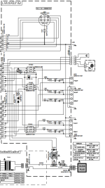
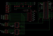
So I just made a super simple PMOS soft start.
Since I had a simple capacitance multiplier in the HT/B+ voltage anyway, I figured that it would be nice to connect the two together.
It also detects when the heater voltage drops.

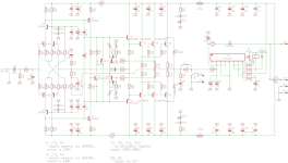
This is pretty crude initial drawing, most values are not critical, except the resistors for the soft start, which can be changed according taste.
D1 and D2 are maybe a little overkill, I didn't test this in practice yet, so maybe to can be left out or replaced by a resistor.
The value of the zener diode needs to be close to the heater voltage.

R12 is just there to release some heavy lifting on Q2.
Otherwise there will be a huge but very small power spike when being switched.

R9 is just a test load, can be dismissed.
I would recommend putting a small 22uF or 47uF capacitor on the output of M2.

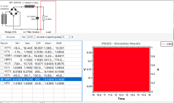
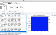
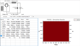
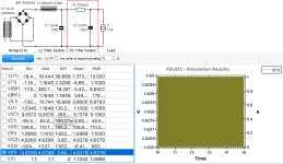
If people are interested, I can show some switching plots, but there isn't anything fancy going on or to see.
The soft start delay is now roughly 2 seconds, after that M2 will switch on to be at full about 0.5-1s later.

I am open to some simplifications or other ideas.
The goal here was to be cheap and simple, and I think this will just work fine in practice 🙂 🙂

Heater_and_HT_switcher.png

How high resistor values for voltage divider, to measure Bias of ESL

I only get results nowhere near what it should measure. (i might still be loading it to hard when measuring.
)so my question what amount of Mega Ohm would be ok for R1 and R2
1698946110184.png

I now used R1 12M and R2 220M.
but all measurements i did , do not come close to the stated Bias, example a 2.5Kv bias from er audio gets me only 800 volt 🙂 so clearly i might not use high enough values ? or is it broken, its pretty annoying to troubleshoot if your measurement is so far off 🙂

Attachments

  • 1698946057488.png
    1698946057488.png
    20.6 KB · Views: 103

Tubes for sale

Sale:
SО-242 – 1 pc.
SО-244 – 3 pcs.
SО-257 – 1 pc.
1N3S – 1 pc.
2D7S – 9 pcs.
2S4S – 1 pc.
4C14S – 10 pcs.
5C3S – 244 pcs.
5C3S (black plate) – 9 pcs.
5C4М – 39 pcs.
5C4М metal base – 4 pcs.
5C4S – 211 pcs.
5C4S shaped flask – 97 pcs.
6А10S – 1 pc.
6B8S – 5 pcs.
6D13D – 1 pc.
6D16D – 122 pcs.
6D16D-R – 7 pcs.
6D24N – 27 pcs.
6Е1P – 182 pcs.
6E3P — 1 pc.
6Е5 – 2 pcs.
6Е5S – 83 pcs.
6J4P – 148 pcs.
6J32P – 73 pcs.
6N1P – 72 pcs.
6N1P-V – 22 pcs.
6N1P-Е – 10 pcs.
6N1P-ЕV – 1 pc.
6N2P – 1 pc.
6N2P-ЕV – 268 pcs.
6N5S — 30 pcs.
6N6P – 1380 pcs.
6N8M – 1 pc.
6N8S – 290 pc.
6N8S metal base – 52 pcs.
6N8S metal base hole plate – 31 pcs.
1578 metal base – 1 pc.
6N9М – 1 pc.
6N9S – 267 pcs.
6N9S MELZ metal base – 82 pcs.
6N9S Tantal metal base – 14 pcs.
6N13S – 54 pcs.
6N23P Voshod – 360 pcs.
6N23P Raflektor – 279 pcs.
6N23P-ЕV – 481 pcs.
6P3S - 273 pcs.
6P3S shaped flask - 2 pcs.
6P3S-Е - 4 pcs.
6P6S - 40 pcs.
6P14P – 163 pcs.
6P14P-К – 48 pcs.
6P14P-ЕV – 238 pcs.
6P14P-ЕR – 50 pcs.
6P42S – 10 pcs.
6P44S – 25 pcs.
6P45S – 124 pcs.
6S2S - 119 pcs.
6S4S – 13 pcs.
6S5S – 1 pc.
6S15P – 46 pcs.
6S18S – 1 pc.
6S33S – 27 pcs.
6S33S «Svetlana» – 4 pcs.
6S33S-V – 102 pcs.
6S33S-V «Svetlana» – 1 pcs.
6S41S – 23 pcs.
6S45P-Е – 118 pcs.
6F3P - 198 pcs.
6F6М1 – 3 pcs.
6F6S – 2 pcs.
10J12S – 1 pc.
10P12S – 7 pc.
30P1S – 10 pcs.
30C6S – 47 pcs.
GI7BT — 25 pcs.
GM70 – 61 pcs.
GMI-6 – 66 pcs.
GMI7-1 – 11 pcs.
GMI-26B – 1 pc.
GMI-30 — 40 pcs.
GMI-32B-1 – 3 pcs.
GMI-38 – 30 pcs.
GMI-42B – 21 pcs.
GU4 — 25 pcs.
GU13 — 18 pcs.
GS35B – 17 pcs.
GU33B – 13 pcs.
GU43B-1 – 8 pcs.
GU46 – 25 pcs.

DIY 6-24 crossover Build Guide

Greeting all, I rcvd my 6-24 Crossover essentials kit and greatly appreciate the 12-page copyrighted doc from the designer, Nelson Pass. Is there also a build guide such as has been graciously provided by 6L6 for other kits? I see mention of one, but can't locate it in the ether. This will be my first build since Kraft r/c and Heathkit HF radios with my Dad in the late 70's, so I'm looking for as much initial guidance as possible. Thank you.

Behringer SRC2496 issue

Hi all, i searched around but it's seems old posts where I can't found proper solution.. I have an ULTRAMATCH PRO, after working with Minidisc, Laptop to connect with a decent audio output to my stereo, I seen that the left output channel is more quieter rather than right channel... already tried with different cables or sources, no change...

I tried to quick check the inner board. but seems quite ok, there is anything that I can do/check? if it's gonna be too complex I'll take a good optical to RCA converter.... but maybe here there is a good expert that can guide me to upgrade/provide good maintenance...

thank you very much in advance..

Igor

Classe Thirty Upgrades?

I'd first like to say that this is a GREAT forum! I have learned much just reading about, so thank you all.

Now, on to the project at hand. I have an unmolested Classe Thirty that needs attention. I am pretty happy with it overall, but it was their entry level offering. Fortunately, there are remarkable similarities between the Classe' pre's of that period (Thirty, CP-30, CP-35, CP-40, etc). When coupled with the technological advancements since 1992, I am confident much can be gained within the existing platform. That said, here is the list of potential areas of interest.

1. Power supply: -Capacitors (4x Nichicon VX 1000uf/63v, 2x Phillips HP 3300uf/25v) I did notice the CP-35 had 4700uf caps. -Regulators (L7815CV, 7805A and MC7915C).
2. Phono stage: There are a few electrolytic's which could easily be replaced with Nichicon KZ and ES for NP's.
3. General opamp: This thing is packed full of OP27's and it seems those should be the first to go. I am planning to put adapters so they can be swapped more easily.

That is where I am at the moment. I know there are opamp discussions all over this forum, but never having actually changed one, I felt an inquiry within reason. I would prefer to find direct replacements if at all possible. I would also like to avoid major design modifications as this just my way of familiarizing myself with the components in preparation for a full-on DIY pre. Idea's?

Attachments

  • IMG_1361.jpg
    IMG_1361.jpg
    955.9 KB · Views: 760
  • IMG_1362.jpg
    IMG_1362.jpg
    856 KB · Views: 539
  • IMG_1363.jpg
    IMG_1363.jpg
    825.6 KB · Views: 502
  • IMG_1365.jpg
    IMG_1365.jpg
    984.5 KB · Views: 868

Topping E70 SMPS part (IC) identification

Hello guys!
I need some help.
SMPS regulator on the picture is from Topping E70 DAC.
The SMPS IC converts 5V to +/- 5.6V, which feed the analog part of Е70.
Its manufacturing marking, evident from the photo, is something like DP0 3U7.
Do any of you have any idea what IC is?

Attachments

  • Clip_3.jpg
    Clip_3.jpg
    159.1 KB · Views: 483
  • Topping E70_resize.jpg
    Topping E70_resize.jpg
    618.3 KB · Views: 1,324

NOS Hypex fusion plate amps

Hypex finally introduced FIR filters for the Fusion amp range of plate amps. This allows for 4000 taps on the input and 1500 taps each for the outputs. We have FIR capable versions in stock here, you can also upgrade some of the older amps if the hardware revision is new enough, if you get in touch with us we can help steer you so that you can accomplish that. We also have quite a few of the older revision amps in stock that still provide some of the best hardware available in a plate amp even without FIR, there are available at 25% off currently!!

STL file for simple phase plug?

Does anyone have an STL file for a basic bullet shaped phase plug which can be scaled in a slicer? I want to add a phase plug to a midbass driver, but can't find a suitable design on line for 3D printing. I've come across some similar shapes, like nose cones for model rockets, but they're hollow and need to be filled for drilling and mounting.
  • Like
Reactions: justanalogue

Yet Another Adcom GFA-565 Thread

Hello Everyone. I have been posting on a different Adcom thread as I have been working my way through a restoration of an old Adcom GFA-565. Rather than add to the bottom of that long and very old thread, I decided to start posting my project here on a nice new thread..

The initial posts for this project can be found at:
http://www.diyaudio.com/forums/solid-state/114702-damaged-adcom-565-monoamps-3.html#post4605057

For Sale Modern LEACH amp + softstart/ on-off (1x pcb set)

Friends I have for sale pcb for LEACH amplifier

2x pcb LEACH (all on one board - AMP, PSU, PROTECT)
1x pcb softstart + On/Off
1x programmed Attiny

Price 40€ + shipping

Payment: PayPal, wire transfer
worldwide

Attachments

  • Leach-SCH-Final.png
    Leach-SCH-Final.png
    201.7 KB · Views: 178
  • Soft-Start-3-S-sch.png
    Soft-Start-3-S-sch.png
    69.1 KB · Views: 195
  • IMG_20231106_111103.jpg
    IMG_20231106_111103.jpg
    489.1 KB · Views: 185
  • IMG_20231106_110729.jpg
    IMG_20231106_110729.jpg
    229.1 KB · Views: 187

Building PA Speakers (HF/LF Ratio)

I've been working in Audio as a hobbyist for the last 20 years, so i'm pretty familiar with it all. Having said that I've spent the last year repairing speakers for a company i work for in my spare time.

So, onto the question ... i'm going to have a go at putting together some good quality PA speakers to use on my own rig .. is there some form of calculation you can do .. or a general rule of thumb for sizing woofers and HF Drivers to balance sound ?

Apologies if this has been asked already, but i did search and couldn't find anything.

Thanks
Dave

For Sale FH9HVX (Finished in 4U box)

Friends since I want to move on sonically and I am currently working on SA2014, ...this also sonically excellent amplifier FH9HVX I decided to put up for sale! I made it with love and gave 100% effort to every little detail. Sonically it can compete with amplifiers up to 2000 Euros

POWER OUTPUT
100W (8ohm) / 155W (4Ohm)
No HUM!

INSIDE:
1x softstart KA1 (inc. dc blocker)
2x FH9HVX (incl. premium parts)
2x All Cee’s (incl. 4x12.000 uF)
2x SSR from LKA

2x 500W toroid from TOROIDY.PL (audiograde)

Input cinch: FURUTECH FT-903 (G)
Output Terminal: ETI BP-20C

Only for serious buyers, ...offer price

Dispatch: Only EU
Payment: PayPal, Bank transfer

Attachments

  • IMG_20230911_195741.jpg
    IMG_20230911_195741.jpg
    405.2 KB · Views: 114
  • IMG_20230911_195815.jpg
    IMG_20230911_195815.jpg
    296.6 KB · Views: 106
  • IMG_20230911_195824.jpg
    IMG_20230911_195824.jpg
    184.6 KB · Views: 96
  • IMG_20230911_195905.jpg
    IMG_20230911_195905.jpg
    282.9 KB · Views: 99
  • IMG_20230911_195919.jpg
    IMG_20230911_195919.jpg
    244.9 KB · Views: 100
  • IMG_20230911_195945.jpg
    IMG_20230911_195945.jpg
    259.9 KB · Views: 103
  • IMG_20230911_200102.jpg
    IMG_20230911_200102.jpg
    285.1 KB · Views: 106
  • IMG_20230911_200111.jpg
    IMG_20230911_200111.jpg
    266.6 KB · Views: 122

For Sale Nakamichi DAC-101 (2xTDA1541A S1 inside)

As stated in the title, I'm selling this rare Nakamichi DAC (used). It works perfectly as it should. The physical condition is about 7/10.

What makes this DAC 'special' is the chips it uses, which are two TDA1541A S1 chips (see the photos).

So, If you are looking for these chips but are concerned about getting fake ones, you may to consider buying this DAC.

This unit is gone
I still have 2 more, see post #3 => all sold!!

Screenshot_20230916-115742~2.png


Screenshot_20230915-183719~2.png

Screenshot_20230915-183708~2.png
  • Like
Reactions: OtisCampbell
Projects by fanatics, for fanatics
Get answers and advice for everyone wanting to learn the art of audio.
Join the Community
507,499
Members
7,874,774
Messages

Filter

Forum Statistics

Threads
405,606
Messages
7,874,774
Members
507,499
Latest member
HFRI