Context: I've been troubleshooting a persistent biasing issue of my DIY Class A/B amplifier. The amplifier bias drifted to infinity or 0 when using linear transformer-based double mono PSUs. The same amp biased as expected when I switched to SMPS modules, which led me to believe that the problem may lie with linear power supplies. After some examination and testing, I suspect that one of the two transformers can be malfunctioning. Any insight or suggestions for additional tests would be greatly appreciated.
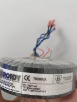
Transformers: For the measurements only one transformer was connected each time. One primary connected to Neutral (N) and the other to Line (L), with the "0" connected to the chassis ground and power Earth. Please see the attached picture for transformer specifications and wires. Transformer #1 and Transformer #2 are supposed to be closely identical in specs, but their measurements suggest otherwise.
Measurements between secondaries with DMM:
Tx#1
Blue1 Blue2 26.41V
Blue 1 Black1 0.48V
Blue1 Black2 26.5V
Blue 2 Black1 25.7V
Blue2 Black2 0.3V
Black 1 Black2 26.7V
Tx#2
Blue1 Blue2 26.7V
Blue1 Black1 4.17V
Blue1 Black2 21.6V
Blue2 Black1 30.2V
Blue2 Black2 4.5V
Black1 Black2 26.5V
Measurements of secondaries in reference to 0:
Tx#1
Blue1 17.7V
Blue2 8.2V
Black1 16.9 V
Black2 8.3V
Tx#2
Blue1 144.2V
Blue2 170 V
Black1 137.2V
Black2 162V
Measurements of secondaries in reference to 0 with flipped phase (reversed the plug):
Tx#1
Blue1 17.4V
Blue2 8.3V
Black1 16.6V
Black2 8.6
Tx#2
Blue1 51.3V
Blue2 27.4 V
Black1 49.2 V
Black2 25.7
The discrepancies in readings are suspicious and alarming, that's why I came here to ask for any insights into potential causes or further diagnostic steps. Thank you for looking into it.
Attachments

There seems to be a conduction between winding(s), including the primaries. It is a dangerous situation, and you should remove the transformers and make isolation/continuity tests without any power applied and report your results here.
Don't try to make further live measurements, they could end up being lethal
Don't try to make further live measurements, they could end up being lethal
No complicated schematics for testing this are involved:
1. INLET.E --> Chassis --> Tx 0
2. INLET.N --> Tx Primary 1
3. INLET.L --> Tx Primary 2
I have tested for continuity:
The primaries show continuity with a resistance of 5.7R.
The secondaries show continuity only between blue-to-blue and black-to-black wires both pairs having a resistance of 0.36R on both transformers
All of your secondaries are measuring 26-27 volts, which sounds right for a 25V transformer.
I would proceed with connecting the transformers to the power supplies and measuring the DC voltages.
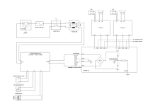
It would be helpful if you posted schematics of your power supply and amp, along with some photos and description of how you measured the bias.
As far as all your transformer measurements go, it is normal to see voltages like that when the secondaries are floating. I just measured an 18 X 2 toroid, and one of the secondaries measured 72V with respect to ground, and 19V with respect to the other secondary, yet I could connect that wire to the other secondary and ground the connection (as you would typically do to connect two secondaries in series and create a center tap) without any issue.
I would proceed with connecting the transformers to the power supplies and measuring the DC voltages.
It would be helpful if you posted schematics of your power supply and amp, along with some photos and description of how you measured the bias.
As far as all your transformer measurements go, it is normal to see voltages like that when the secondaries are floating. I just measured an 18 X 2 toroid, and one of the secondaries measured 72V with respect to ground, and 19V with respect to the other secondary, yet I could connect that wire to the other secondary and ground the connection (as you would typically do to connect two secondaries in series and create a center tap) without any issue.
Having different voltages when the plug is flipped means something abnormal around the primary or PE connection
The OP is measuring microamp currents across a 10Mohm DMM caused by capacitive coupling between the windings. The transformers are not the problem.
Ed
Ed
WE STILL NEED THE SCHEMATICNo complicated schematics for testing this are involved:
1. INLET.E --> Chassis --> Tx 0
2. INLET.N --> Tx Primary 1
3. INLET.L --> Tx Primary 2
I have tested for continuity:
The primaries show continuity with a resistance of 5.7R.
The secondaries show continuity only between blue-to-blue and black-to-black wires both pairs having a resistance of 0.36R on both transformers
Sounds like your biasing scheme is depending on the rail voltage being fixed - transformer supplies output voltage varies as the mains voltage varies over the day due to varying load on the mains. Biasing circuits should not be sensitive to rail voltage...The amplifier bias drifted to infinity or 0 when using linear transformer-based double mono PSUs. The same amp biased as expected when I switched to SMPS modules, which led me to believe that the problem may lie with linear power supplies.
Hello everyone,
I wanted to thank you all for the helpful insights and support. After many frustrating months, I believe I've finally identified the root cause - I was not connecting the 'CH.GND' point on the capacitor bank to Earth/ground. Instead, I incorrectly wired it straight to the power ground of the amplifier module.
Now it makes sense why things have been so unstable! I clearly misunderstood how the power supply wiring should be connected. After closely reviewing the schematics again, I realized the 'CH.GND' point on the capacitor bank must connect to Earth ground, while the PGND connects to the amplifier module's power ground.
Interestingly, this setup had been working fine previously, until it didn't. Since then I've been stuck in a "vortex of doom". I've experienced this scenario multiple times: first testing amplifiers with my linear supply and having stability issues (only when speaker load was connected). Then switching to my SMPS without soft-start protection. It is working until an amplifier channel gets damaged during a random power-on - (apparently) an overconfident mistake on my part that happened again recently. Lots of head scratching, repairing, and sending things for repair and doing the same things over and over without realizing the underlying issue causing all the trouble.
It seems the combination of using an SMPS without soft start and incorrect linear supply wiring was the phantom menace plaguing me for so long. I can't fully test this yet, as the TSSA V1.8 amplifier that was unstable now has a faulty channel again. I'll try the MIrand A1 V12 modules next to see if PSU works.
In any case, thank you all again for your patience and help. The vortex of doom is not yet over, but I finally have some direction thanks to your feedback. Your comments have given me clearer understanding.
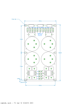
PS. I'm attaching the relevant schematics and illustrations to provide better context around my previous issues. Hopefully these visuals will help further clarify where things had gone wrong.
I wanted to thank you all for the helpful insights and support. After many frustrating months, I believe I've finally identified the root cause - I was not connecting the 'CH.GND' point on the capacitor bank to Earth/ground. Instead, I incorrectly wired it straight to the power ground of the amplifier module.
Now it makes sense why things have been so unstable! I clearly misunderstood how the power supply wiring should be connected. After closely reviewing the schematics again, I realized the 'CH.GND' point on the capacitor bank must connect to Earth ground, while the PGND connects to the amplifier module's power ground.
Interestingly, this setup had been working fine previously, until it didn't. Since then I've been stuck in a "vortex of doom". I've experienced this scenario multiple times: first testing amplifiers with my linear supply and having stability issues (only when speaker load was connected). Then switching to my SMPS without soft-start protection. It is working until an amplifier channel gets damaged during a random power-on - (apparently) an overconfident mistake on my part that happened again recently. Lots of head scratching, repairing, and sending things for repair and doing the same things over and over without realizing the underlying issue causing all the trouble.
It seems the combination of using an SMPS without soft start and incorrect linear supply wiring was the phantom menace plaguing me for so long. I can't fully test this yet, as the TSSA V1.8 amplifier that was unstable now has a faulty channel again. I'll try the MIrand A1 V12 modules next to see if PSU works.
In any case, thank you all again for your patience and help. The vortex of doom is not yet over, but I finally have some direction thanks to your feedback. Your comments have given me clearer understanding.
PS. I'm attaching the relevant schematics and illustrations to provide better context around my previous issues. Hopefully these visuals will help further clarify where things had gone wrong.
Attachments
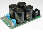
From your description, it sounds like your amplifier and speaker were connected to the power supply through the ground lift resistor. Have you measured that resistor to see if it is still the correct value? The picture of the power supply board shows an unusually low wattage resistor for that application (assuming it is R1), so it may have gone open circuit, which would explain why it was originally working and then stopped.
- Home
- Amplifiers
- Power Supplies
- Suspicious Tx measurements – need insights