Audio Note DAC 1.1x signature: Is it worth to upgrade to AD 1865 N-K?

Hello,

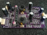
I have a factory manufactured Audio Note DAC 1.1x signature with a lower spec'd AD 1865 DAC chip. Can anyone confirm in how far there is a real improvement when the DAC chip is upgraded with an AD 1865 N-K? Is there a reliable source for that vintage DAC chip? There are many offers from China and Hongkong, all pretending they are selling original stock...

Best regards
Stefan

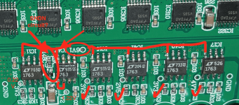
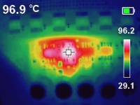
Are these two LT1763 chips in the power supply section defective?

Hi Folks,

I'm trying to troubleshoot the following two issues in a section of a DAC power supply. I don't have schematics. The DAC is working but I'm concerned about the heat. There is a row of 6 LT1763 chips that are part of power supply. All 6 LT1763s are connected to Vin = 6Volts, and the same (shutdown?) circuit. The shutdown circuit consists of Vin, a 10Kohm resistor and a switching diode labelled 4148C which might be MMBD4148CA or MMBD4148CC, and possibly other components to be mapped out though I'm not sure how important that is in troubleshooting the two issues.

1. IC42 is running much much hotter than the other LT1763s at 97C. Is this expected when Pin 2(ADJ) is connected to Pin 1 (Vout)? I have verified Vout is 1.22Volts, as labelled on the PCB, and expected from the datasheet.

2. IC11 seems to be defective since Vout is 0.22 Volts - the label is 3.3 Volts. IC11 appears identical to IC15 and IC40, both output around 3 Volts. I haven't been able to verify if any of the surface mount capacitors or resistors are failing, except that they are not shorted or open.

All other LT1763 Vout values are as expected: IC17 (Vout = ~4Volts), IC41 (Vout = ~2 Volts)

LT1763 datasheet: https://www.analog.com/media/en/technical-documentation/data-sheets/1763fh.pdf
the datasheet shows Tjmax is 150C.

I verified the following on IC42:

Pin 8 (Vin) = 6 Volts
Pin 1 (Vout) = 1.22 Volts
Pin 2 (ADJ) Connected to 1
Pin 3,6 and 7 (GND) are connected to GND
Pin 5 (SHDN) is connected to the shutdown circuit described about.
Pin 4 (BYP) is connected to a 103 (10000pF) Capacitor, which is connected to Vout.

I am thinking of ordering two LT1763s but these are quite expensive at $6 a piece.

Attachments

  • Screen Shot 2023-12-23 at 6.37.21 PM.png
    Screen Shot 2023-12-23 at 6.37.21 PM.png
    705.3 KB · Views: 162
  • Screen Shot 2023-12-23 at 6.43.03 PM.png
    Screen Shot 2023-12-23 at 6.43.03 PM.png
    902.5 KB · Views: 156
  • Screen Shot 2023-12-23 at 6.53.24 PM.png
    Screen Shot 2023-12-23 at 6.53.24 PM.png
    139.1 KB · Views: 140

Problems with Philips CD100

Hi folks,

i'm currently troubleshooting a friend's CD100 that has apparently been sitting in a basement unused for 10+ years.
When I first had a look at the unit, more or less nothing worked at all. After doing the most obvious thing (changing the caps in the power supply) the unit still wasn't working.
I then noticed that -18V rail was completely off, which I could trace back to diodes D6266, D6267 and D6268 all being defective. After changing them I now have beautiful -18V as well. After reading up on the CD100, I also changed the famous C2217. As everything was still all over the place, I changed all the blue Philips electrolytic caps in the unit, as my experience from restoring a PM3055 oscilloscope told me they would probably all be out of spec (measuring the removed caps showed me this suspicion was correct).

Now the unit still has a main problem remaining: The laser seems to focus and the CD starts to spin, however the process of reading TOC never seems to finish. It will just continue to spin forever while in this state, unresponsive to any button presses. So far i wasn't able to find the reason for this fault.

Having another check through the unit i noticed that the rails +12V/-12V are not on point, but at +11,8V/-12,2V. Disconnecting the Decoding PCB brings these voltages back to normal. Poking through everything connected to the 12V rail on the Decoding PCB i then noticed that IC6523 (Op Amp NE5532N for left channel) has 0V at output, so probably is defective. However, I would assume that this has nothing to do with reading of TOC and only with no sound output on that channel. Or could a defective IC6523 disturb the 12V rail enough to somehow affect other stuff connected to this rail?

I do not want to randomly change components on the decoding PCB before sorting out the TOC reading issue - can someone here provide me some insight?

Cheers,
Carmen59

CXA1800.1

Cxa1800.1 volume level is chaotic.
When I have the volume turned down it is really loud when I turn the volume up the bass starts chopping it sounds like I got a wire loose but all wires have been checked and all of my splices are solderedand shrink wrapped I have went thru the manual front to back I've removed my lc1i and changed it from low input to high and still the same thing it was running fine but I changed from a cheap $5 line leveler from Walmart and it is the only thing that kinda works. I'm st a loss here talked to Todd at edburg amp repair and he sent me here specifically for papazbill but any help is welcome. Thanks

Looking for circuit recommendations for MM phono and "regular" preamps

I'm seeking recommendations for pre amp circuits (MM Phono and "regular preamps) that add a lot of warmth to the signal with little to no noise. If the result is amazing I might even use a SS power amp. This will be a retirement project so I'd like to limit the essential tubes to those that are affordable. My phono stylus is a AT-VM95SH. Other inputs will be a DAC, tuner, and Denon CD player.

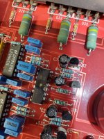
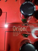
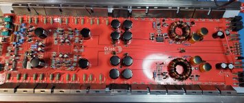
Orion 275R

Orion 275R 0770-5110 Rev D 8/16/99.

Never seen a PIC16 damaged this bad. I suppose this is going to be non repairable unless someone has the firmware laying around? Another DIP16 blown to shreds. Not sure what it is.

Not familiar with the old school stuff but I do know how to program and have the tools to do it.

Attachments

  • 20220124_151042.jpg
    20220124_151042.jpg
    583.4 KB · Views: 159
  • 20220124_151048.jpg
    20220124_151048.jpg
    523.6 KB · Views: 146
  • 20220124_151054.jpg
    20220124_151054.jpg
    422.4 KB · Views: 136
  • 20220124_151119.jpg
    20220124_151119.jpg
    437.8 KB · Views: 185

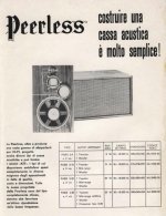
Vintage Peerless 3-25 Alnico speaker kits Woofers, Midranges, tweeters and crossovers 8 of each.

I have the parts from the Early Alnico Peerless 3-25 speaker kits I have 8 of the Peerless CM120W 12" woofers, 8 of the Peerless G50MRC midrange, 8 of the Peerless MT20HFC tweeters and 8 of the correct Peerless 3 way crossovers they are all-in very good condition having been in cabinets all of their lives. These are pretty efficient and reproduce vocals
confusingly well. I can't tell people what they sound like or if they will like them, these are probably going to appeal to someone familiar with the speakers or with good Alnico
speakers from that era. I am willing to sell the kits in sets, buy one pair 2,3 or 4 , pair. I ship to the continental USA one pair shipped for $250 2 pair $450 all 4 pair shipped $800 These are all rated as 8ohm and all test at an average of 7.8 with very little deviation from that Im open for trades but it would have to be pretty unique.


  • IMG_4142 (2).JPG
    IMG_4143 (2).JPG
    IMG_4144 (2).JPG
    IMG_4145 (2).JPG
    IMG_4146 (2).JPG
    IMG_4147 (2).JPG
    IMG_4149 (2).JPG
    IMG_4150 (2).JPG
    IMG_4153 (2).JPG
    IMG_4156 (2).JPG
    pabs1.jpg

Attachments

  • pabs.jpg
    pabs.jpg
    81.2 KB · Views: 861

Amplifier with the current output, JFET and BJT circuit

Hello!

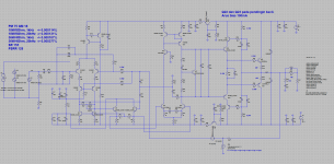
I would like to thank lineup and Zoran. Their suggestions led me to the following circuit:

Current_Amp_19V_Circuit.JPG


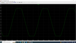
The output power is 3.5W into 8 ohms:

Current_Amp_19V_WF.JPG


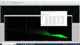
Despite the lack of global negative coupling, THD is ~ 1%:

Current_Amp_19V_FFT.JPG


The frequency response extends up to 350kHz:

Current_Amp_19V_FR.JPG


lineup: https://www.diyaudio.com/community/threads/sound-of-the-bipolar-transistors.402327/post-7437895
Zoran: https://www.diyaudio.com/community/threads/sound-of-the-bipolar-transistors.402327/post-7480371
  • Like
Reactions: cumbb

Another Idss measurement jig

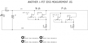
As the title say, here is another one.

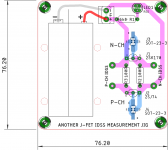
I find it convenient if battery is fixed on pcb via cable ties, no need to reverse battery polarity for N-ch and P-ch.
All other designs including a group buy pcb, needed battery polarity to be reversed.
sot-23 can be DSG or SDG.

The big donuts near text N-ch idss and P-ch idss is where you connect multimeter.

regards
prasi

Attachments

  • SCH.png
    SCH.png
    3.7 KB · Views: 774
  • LAY.png
    LAY.png
    33.8 KB · Views: 773

Hitachi MOSFETS 2SK134/2SJ49 pairs....NOS lots of them

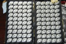
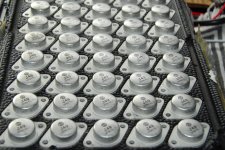
I have about 85 of each 2SK134 and 2SJ49, new in the original flats from about 1988 or so. I am the original owner having bought them from a disti I worked at back then.

I would like to trade for any of the following.

SITS, 2SK182, 2SK82 2SJ28 etc Sony etc
Tokin THF51S
Any others SITS??
Parts for PASS M2 J2 SissySit etc.
DIY or similar power amp chassis with heatsinks or preamp type chassis

Xfmrs for SissySit, Cinemag, Edcor or Jensen

Let me know what you have to trade, PASS related or otherwise.

Cheers

Attachments

  • DSC_6702.jpg
    DSC_6702.jpg
    1.1 MB · Views: 706
  • DSC_6704.jpg
    DSC_6704.jpg
    842.6 KB · Views: 478
  • DSC_6703.jpg
    DSC_6703.jpg
    864 KB · Views: 515

Please check my work before I return a vintage oscillator as "not working"

I bought an HP 651B test oscillator on eBay, the listing said "This has been tested and it is in good working order".

When I powered it on, I was not able to get a signal out of either of the output jacks, nor was I able to make the needle move. I did get it to bounce when switching some of the knobs and things, but that's it.
I was about to return it, but I thought "Maybe I'm just an idiot". Does the needle only move when connected to a proper load? Is running this straight in to my oscilloscope not the correct way to test it? I would much prefer to keep and use this unit than return it, so if theres any possibility that it was user error, I'd like to correct that.

microTower Zobel and Driver Rewire Puzzle

Hello everyone! It has been a while.

Last time I was here, I had just replaced the (2x) EL-70 drivers in my Planet10 microTowers with (2x) Pluvia 7.2HD. At the time, I had trouble deciding whether to go with series or parallel wiring. The EL-70s were nominal 4ohm, so I originally went with series wiring for nominal 8 ohm total. However, the Pluvias are nominal 6 ohm, so I had the conundrum of choosing 12 ohms (series) or 3 ohms (parallel).

Ultimately I chose the lazy way (12ohms, series) because the speakers were already wired that way and my Tubelab SSE has 4, 8 and 16 ohm taps (went with the 16 ohm taps and it sounds excellent).

Trouble is, now these speakers do not get along at all with my "Wiener" TPA 3118 Amp. When I ordered it, I selected the 4 ohm output filter configuration and it is fairly well-known that the results can be pretty terrible if these amps are played with inappropriate speaker loads, especially such a massive mismatch of 4 ohms vs. 12 ohms and especially when the rising impedance curve of these "naked" drivers makes matters in the top end exponentially worse for the Wiener (not so much for the SET!). This isn't just theoretical - it sounds horrific.

gmarsh, designer and builder of the "Wiener", concluded that a Zobel is a fantastic addition to flatten the impedance and help get the best from the Wiener. I grabbed his code from that post and started playing with it in GNU Octave. (Thanks Gary!) The only way forward to get these speakers to work with the Wiener Amp is to go for parallel wiring, and I might as well add the Zobel while I am at it. The simulations I have done in GNU Octave, with some help from an online Zobel calculator have made this all pretty straightforward.

Question #1: The Pluvia 7HDs wired in parallel will have an ReVc of 2.7 ohms (nominal 3 ohms impedance). This will not be ideal for the 4 ohm tap on my SET, nor the 4 ohm target load of the Wiener Amp. Should I add an extra 1 ohm of resisance? (could be accomplished by adding a 2 ohm 10W resistor in series with each driver).

Question #2: Right now the naked speakers running in series (12 ohms nominal, no Zobel) are a very nice match with my SET. Will rewiring as proposed and adding a Zobel screw that all up?

Any feedback will be very much appreciated! Thanks.

First project : Troels PMS with SBacoustic drivers ; advice and help most welcome

After building a proven design I want to make the deep plunge. And big plunge it is.
Having several bookshelf 2-way speakers I would like to go 3-way for this one.
I think it would not be easy to bring it to a success myself, but if some with enough experience would like to guide and help me out that will be much appreciated.

Troels PMS http://www.troelsgravesen.dk/PMS.htm is very appealing to me and would like to use is as inspiration for my design. It has many challenges.
Before spending heaps of money on it, I would like to make some proper simulation to see where we can land.

BOX design :
What I like about the PMS design is the limited depth of the speaker making it look like a panelspeaker.
For my design I will not go as wide but limit it to 400mm/ 16".
Hight will be 1050mm / 41.5" and depth around 130mm/5.2"

This would give an estimated volume of 26L for the woofer and 6L for the mid's.

DRIVERS :
Troels used ScanSpeak discovery drivers for his design. Good drivers but I have the impression that SBacoustic has the best price/quality ratio for this segment of drivers at the moment.
They are actually also a cheaper so that helps as well.

My drivers choice:
Tweeter : SB26ADC
Mid : SB15MFC30-8
Woofer : SB23NBAC45-8 in a 25L closed box -> -3db =50Hz

Design goals :
Closed box design, sloped baffle
85-87db sensitivity. cabinet will be placed close to the back wall.
Crossover point : Target 300Hz - 3kHZ
Low order crossover if possible.
Impedance : minimum 5ohm
Using VituixCAD

Before starting buying drivers I would like to start with manufacturer traced curves to see where we land. This way I can order drivers and crossover parts for startpoint at the same time to lower costs. During listening and real measurements tests I can order the necessary components locally. But those will be more expensive then.

What I figured out so far :
baffle slope of 8degrees will make a difference of 150mm/5.9" in dept between top and bottom

Driver layout : From TOP FROM tweeter Y Z T
Tweeter : -125 925 0 0 8
MID : -259 -134 -133 -19 8
Woofer : - 564 -439 -435 -62 8

For driver acoustic center I had to make some assumptions : not sure if I come close enough.
Tweeter : 0
MID 5" : 80us / 28mm
Woofer 8" : 110us /38mm

I traced the drivers from the manufacturer website. Traces are attached below.
Those IEC baffle traces I used in the diffraction tool from VituixCAD to generate full space traces.
Each driver was placed in it exact location on the baffle with the mic in the centre. axis distance = 300mm.
Below the different traces. For the woofer a merged was made as well.

ZMA files were created based on the manufacturer traces. For mid and woofer adapted to the different volume in the enclosure module from VituixCAD.


Thats what I have so far.
I dont know if this is sufficient to start thinking about crossover design or some other things need to be tackled first.

Attachments

Woofer repair - vintage Scott 166

I rescued this pair of Scott 166 from a family member who was getting rid of them. These are a sealed 6 1/2" 2-way bookshelf design from the late 70s I believe. Construction appears to be decent with a heavy cabinet, foam filling, an actual crossover network, and a good-sized woofer magnet with a vented pole piece. The cabinets, grills, spiders and surrounds are all in excellent condition visually. Both speakers were playing at low volume briefly when the woofer stopped working on one side; the working speaker actually sounds pretty good. I should have some time between Christmas and New Years and would like to attempt a repair.

Initial investigation revealed that the dead woofer was open-circuit. Since then I have lifted the dustcap, and scraped back the black VC lead glue to find where the break is. It turned out that the VC itself still has continuity (measured 5.9R) and the open circuit is somewhere in the lead between the VC and where it passes under the dustcap and exits the cone.

Questions for the knowledgeable folks here:
  • What solvents can be used on the hard black glue over the VC lead wires? I have acetone on hand, or could pick up some of the box store "lacquer thinner" (per SDS mostly toluene, with xylene, methanol, acetone, and MEK).
  • What are the correct adhesive(s) to (i) cover the VC lead wires post repair, and (ii) reattach the dust cap?
  • Any pro tips on soldering in very close proximity to a paper cone?
Scott 166 troubleshooting.jpg
voice coil DCR 20231028_222539.jpg

woofer back 20231028_221458.jpg
front 20231028_221243.jpg

Mic preamp idea (6N1P + 12AU7)

I've been wanting to both get back in the game of building things that glow in the dark (its been years) and a preamp for my Shure SM7B (that I could use as an alternative to the FetHead that I like) so after the first impulse to simply copy a preamp topolology I saw in a TapeOp article I decided to scratch my head a bit and came up with my own thing. One of the design constraints was a low-ish 240-250V plate supply which I already have in a "brick" form. The choice of a 12AU7 for the WCF was mainly due to the hefty 200V h-k rating which reduces the need to elevate the heaters supply.

I've looked at different topologies, including Aikido cascode with no NFB but settled on 2-stage RC coupled amplfier with "gentle" -20db nfb.

My first desire was to use something fairly uncommon like 6EJ7s strapped in triode for the gain stages, but 6N1P so far has given far better results in simulation (I've tried 6N3P, and other medium-mu triodes in this circuit) plus with 6N1P and other double triodes you only need 2 and not 3 tube sockets.

Looking for critique and hope to proceed to prototype this little "mic warmer".

Regards, Alex

6N1_12AU7_preamp.jpg
  • Like
Reactions: SomekPoland

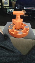
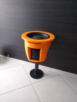
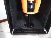
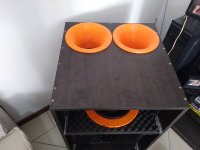
Subwoofer with 3D printed basket for Home Theater

Good day!

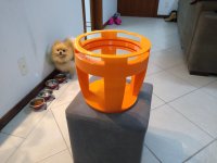
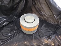
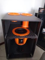
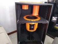
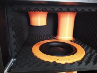
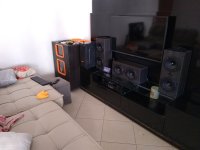
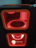
I'm here to share with you guys my latest project: A DIY NdFeB-based Subwoofer with 3D printed basket in a 6th order parallel-tuned bad pass box for my first home theater!
I'm from Brazil and my English grammar skills are not great, so be patient.

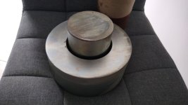
This project was made from scratch, starting with the mathematical modelling of the magnetic circuit. After the validation of the set of equations that relate the magnetic flux density in the gap and the magnetic circuit geometry, I wrote an optimization routine in Mathcad that gave me as a result all the construction parameters for the magnetic circuit, including coil diameter, wire (AWG), number of turns, number of layers, gap height, etc. as a function of the input parameters. Those parameters was the subwoofer Xmax, defined as 25mm (in one direction), coil DC resistance, etc.

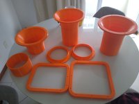
The next step was to design the subwoofer itself. I used Autodesk Fusion (like Solid Works). After the mechanical design, I 3D printed the basket in a Creality Ender 3 Max, capable of printing 30x30x40cm. The magnetic circuit was made using 1020 low carbon steel, with a Zinc galvanization.

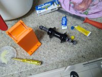
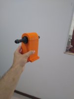
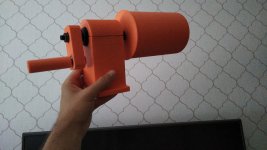
To build the coil, I started building a winder machine using a bicycle hub and my 3D printer. I made the coil using a 3D printed mold, a 0.2mm Kepton sheet and a high temperature epoxy resin.

After that, I started putting all the rest of the pieces together (dual damper system, coil, cone...).

With the subwoofer completed, I used a simple resistor-based circuit in my SPEAKER OUT and LINE IN jack of my PC sound card to obtain the Thielle-Small parameters using REW (Room EQ Wizard). This works like the DATS device from Dayton Audio, but much much cheaper.

With the subwoofer parameters, I designed a 6th order parallel-tuned band pass, from 20Hz to 100Hz using Bass Box software.

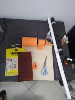
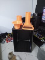
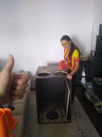
Well, some of the construction photos and the final result are shown. I also 3D printed custom ports and frames for the acrylic windows.

This is just the subwoofer, I build also 5 other speaker boxes for my 5.1 system, but this is subject for another post.

I hope you like, and if you want to see more of my projects, or more photos and videos of this particular project, follow me on instagram: @insanity_bass

If someone have any questions, I will be happy to answer.

Thank you.

Attachments

  • Foto 1.jpg
    Foto 1.jpg
    470.9 KB · Views: 163
  • Foto 3.jpg
    Foto 3.jpg
    212.8 KB · Views: 152
  • Foto 6.jpeg
    Foto 6.jpeg
    318.8 KB · Views: 147
  • Foto 11.jpeg
    Foto 11.jpeg
    316.6 KB · Views: 150
  • Foto 12.jpg
    Foto 12.jpg
    244 KB · Views: 138
  • Foto 14.jpg
    Foto 14.jpg
    292.7 KB · Views: 143
  • Foto 16.jpeg
    Foto 16.jpeg
    261 KB · Views: 144
  • Foto 17.jpg
    Foto 17.jpg
    372 KB · Views: 146
  • IMG_20221023_164102133.jpg
    IMG_20221023_164102133.jpg
    236.1 KB · Views: 147
  • IMG_20230429_175036070.jpg
    IMG_20230429_175036070.jpg
    244.5 KB · Views: 167
  • IMG_20230502_133740166.jpg
    IMG_20230502_133740166.jpg
    234.6 KB · Views: 176
  • IMG_20230506_115936952.jpg
    IMG_20230506_115936952.jpg
    272.5 KB · Views: 188
  • IMG_20230508_120602747.jpg
    IMG_20230508_120602747.jpg
    297.2 KB · Views: 188
  • IMG_20230508_120621885.jpg
    IMG_20230508_120621885.jpg
    313.4 KB · Views: 172
  • IMG_20230508_120631708.jpg
    IMG_20230508_120631708.jpg
    216.3 KB · Views: 162
  • IMG_20230508_120637272.jpg
    IMG_20230508_120637272.jpg
    249 KB · Views: 150
  • IMG_20230508_120647107.jpg
    IMG_20230508_120647107.jpg
    313.6 KB · Views: 154
  • IMG_20230511_115051289.jpg
    IMG_20230511_115051289.jpg
    307.3 KB · Views: 151
  • IMG_20230520_210721240.jpg
    IMG_20230520_210721240.jpg
    159.4 KB · Views: 153
  • IMG_20230520_210752494.jpg
    IMG_20230520_210752494.jpg
    151.7 KB · Views: 144

Passive volume control and line switch, looking for advice

In an earlier thread, I asked about remote volume control of my valve amp system, and two routes were suggested: put a remote controlled pot into the amp, or add a passive volume control.
I'm a little nervous of the electronics work inside the amp, being a complete novice, so I'm exploring the passive volume control first.
There is another ideal requirement, that the amp can be turned on and off remotely. My husband is terrible at leaving it switched on all night.
I'm looking at a 2 channel device on EBay:
https://www.befr.ebay.be/itm/125984...wpu5/e89DsLEHbEL5gUSvJyeU=|tkp:Bk9SR8KPg86WYw
I'm just wondering if I could use the second channel to control a mains switch to turn the amp on and off.
What do you guys think?

Attachments

  • s-l1600.jpg
    s-l1600.jpg
    180.4 KB · Views: 69

Series Caps

Hi, Series Caps on the amp output for speaker " protection " , yes or no ?. ( Ideea being - amp goes bad DC at output, cap = no dc , speakers are " happy " ) .

I know they are used in single supply rail amps with half of the rail voltage on them. that's why we have dual rail power on amps to have 0 ( nearly zero ) dc offset, so no cap needed = better sound?. In 2-way , 2-way speakers there's always a cap for the midrange, tweeter, unless bi-amped ( even in bi-amped cap on tweeter is recomended as I read ).

Let's say in a PA amp, 200W per channel, a 4700uF cap rated ( 80v or so ) for 8ohms it will cut off at around 4 Hz ?, To much current trough the cap?, or the only concern is " worse sound quality" ?.

- Bruno.

Help Tweaking Crossover

I added Raal 70-20r tweeters to my speakers based on a design by Roy Johnsons. I got the specs for the tweeter side of the crossover from Roy and a Zobel design from the owner of Raal. I decided recently to make some measurements. The HF measurements were not so great with a dip at 3000 hz and a big spike at 5000 hz. So I decided to make some changes starting with the Zobel. Measurements are in-room but it is a large room with high ceilings so reflections are not a huge factor.

in the process I measured just the woofer and found that the dip and spke were both present just with the subwoofer. So I am baffled (no pun intended) as to what might cause the woofer to not have a rolloff. It is a simple crossover with a capacitor/coil and resistor for the lowpass and 2.2 uf cap equivalent on the tweeter, Zobel is .68 uf cap and 6.8 resistor.

I cannot see any issues in the woofer section of the crossover. Any idea why I am getting a bit spike with just the woofer, no tweeter connected. see photos. I am very amatuer at all this so I need some help.
Screenshot 2023-12-01 154341.png
IMG_20200714_114652622.jpg

Small 10" dual driver (isobaric) subwoofer built ike the M&Ks

Another small box sub question. I have a pretty tight space in my basement setup, with just one spot for my subwoofer. I currently have a ported 12" cube with an 8" dayton audio DVC driver. I use a 300w class D plate amp to driv ot, but it is set externally so it does not take up box volume or need a big hole cut in the box. It is pretty good, but I can hear the port chuffing at times.

I want to build a new sub, isobaric setup (only because I love the old M&K subs) using 10" drivers. I would build a similar 12 in cube, with one driver facing forward as normal and one mounted on the bottom firing into the box. The then I will finish 3 sides around the bottom woofer, leaving the front open.

1) how do I model this in one of the online sub modeling tools, when choosing appropriate drivers to look at freq response.
2) are the drivers wired in-phase (so the air pressure stays mostly constant), or out of phase?

I am hoping for basically a sealed 10" sub that digs slightly deeper and cleaner than just a single 10" in a 12" cube. Just a bit taller, and with the added expense of a second driver. I would start with my existing sub amp, but I expect I will eventually need a bigger one with more than 300w to power 2 drivers.

Hp 8903b UK only

For sale a Hp 8903b UK only

It has both A weighting and 400hz filters

This has been on my shelf since I bought it around 1 year ago unused by me

I have all the chassis parts and will be together before sending out I took it apart to replace the electrolytic caps but I'm just lazy and it just didn't happen.

Condition wise it has some marks as you might expect, the power switch has been replaced at sometime in its life and has been put in upside down, I've tested distortion see photos but if your thinking of buying let me know if there's any other tests you want me to do. The chassis feet may or may not be broken.

£350 ono

This is in South Manchester I would MUCH prefer pickup
20231228_171659.jpg
20231228_171641.jpg
20231228_171648.jpg

looking to turn old PC into DSP

hi,
i am looking for a way to configure every channel of my audio output with other effects (pitch, filter, equalizer, gain ect.). i am on my main pc using an linux distro by the name of "Pop!_os" and are not willing to switch. i also have a second pc that is not in use. on pop os it is not possible to select seperate filters for every audio channel. on my second pc i have a lot (5) of different audio output channels and an audio input channel. so i figured i could use this old pc as a kind of a dsp/crossover, but i do not know how and what software or linux distro to use (or if this is even possible). that's why i made this post.

Thank you for reading and maybe hopefully responding

horn woofer ideal TS parameter

Hi, i am new to folded horn and try to read as much as i can but as with forums and internet is, i get all kind of mixed confusing or oposite answers...in short what i am looking at is what would be the target "ideal" TS parameters to aim for a 15 inch driver for a horn loaded enclosure of about 50 inches long taper.

also what is the effect on resonance or frequency response of the overall enclosure about the volume of the rear closed chamber.

i have diy Hartsfield prototype on hand and try to play with it and get the much out of it that i can.

thanks.

KEF Reference 101 Loudspeakers. Crossover update

for anyone interested I'm going to describe my renewal of the crossovers of these classic speakers which I've had from new.

First, after I removed the 'woofer' to get access to the crossover inside, there is a screw underneath on the outside once remover the crossover was still well attached and I had to lever it off, which was awkward inside the cabinet!, there was four sticky pads holding it there.

The first things I noticed were that the 15R 6W vitreous enamel resistor looked soiled with corrosion(?), a white powdery coating. and two 10v (only!?) caps on the protection circuit had corroded PCB tracks underneath. This was on BOTH crossovers!

I enclose a picture of one of the crossovers

Attachments

  • KEF 101 Crossover.jpg
    KEF 101 Crossover.jpg
    231 KB · Views: 4,241

  • Article Article
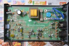
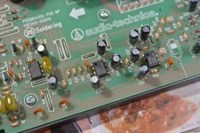
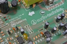
Audio Technica AT-MCA20a microphone preamplifier

I bought this Audio Technica AT-MCA20a microphone preamplifier on Yahoo.jp auctions for 1600 yen (about $12 US). As a curiosity and learning tool, to see how it was made.

Here, for your viewing pleasure, are photos on the inside.

It's discontinued but recently sold for about $200. It's billed as being for security/surveillance rather than music/recording but it seems to be built to commercial broadcasting standards. The THD of 0.1% or less at1kHz, +4dBm seems respectable, but it's hard to judge.

■ Microphone amplifier
■ 1ch
■ Input impedance 2kΩ
■ Reference input level MIC -50, -40, -30dBV switching
■ Output impedance: Rated 600Ω (effective 200Ω)
■ Standard output level: +4dBm (LINE) -26dBm (MIC)
■ Maximum output level: +14 dBm (LINE) -16 dBm (MIC)
■ Output ATT: 30dB
■ Frequency response: 40-25,000Hz
■ Low cut: 200Hz, -6dB/oct
■ Total harmonic distortion rate: 0.1% or less at1kHz, +4dBm
■ Noise level: Input conversion (150Ω termination)-115 dB or less (JIS-A)
■ Phantom power supply: 12V
■ Power supply: AC100V (50/60Hz)
■ Power consumption: 0.8W
■ Weight: 730g

I realized after the fact that the phantom power supply is only 12V so it won't work with my AT4047SV even to test. Drat.

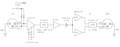
As for the circuit, the linear power supply comprises a small transformer, bridge rectifier, filter cap, and a 24 V voltage regulator. A set of Zener diodes creates +12 V and -12 V supplies and a virtual ground for running the three op amps, a NEC C842C, JRC 2068DD, and JRC 4556AD. The 4556 is a dual hifi op amp, it's the output stage, the 2068 is a low noise dual op amp, used as the input stage and buffer. The C842 is a high speed, general purpose op amp so it's probably part of the power supply. Interestingly, there are four very small transistors near the C842... I don't know their function.

Attachments

  • AT-MCA20a_manual.pdf
    AT-MCA20a_manual.pdf
    187.4 KB · Views: 122
  • image001.jpg
    image001.jpg
    440.4 KB · Views: 117
  • image002.jpg
    image002.jpg
    358.9 KB · Views: 118
  • image003.jpg
    image003.jpg
    300.6 KB · Views: 101
  • image004.jpg
    image004.jpg
    307.9 KB · Views: 105
  • circuit.png
    circuit.png
    30.5 KB · Views: 115
  • NJM2068_j.pdf
    NJM2068_j.pdf
    159.5 KB · Views: 105
  • njm4556a.pdf
    njm4556a.pdf
    132.6 KB · Views: 103
  • UPC842_NEC.pdf
    UPC842_NEC.pdf
    561.5 KB · Views: 97

Building a DIY DAP reusing old Android with Custom ROM

Hi, everyone,
So basically I am dreaming of a very ambitious project which seems mostly impossible right now. So before jumping into the project i just wanted to know more about certain things. That's why i am posting here.

I want build a DAP{or close to a DAP} reusing old android phones giving them some extra life and reducing e waste.

I want to achieve these following things:

1. A DAP or close to DAP level sound quality.
2. A custom Android OS containing only Audiophile related apps and programs and nothing else for clutter free music experience.

Now, I am seeking help from you guys to enlighten me with your knowledge and make this project possible. I am sure that if this project become possible some other enthusiasts might try this and give a fresh breathe to old phones.

Thanks in advance.

Raspberry Pi4B - streaming music from my network PC ?

I am new to Raspberry Pi.
I'm playing with the Pi4B with no HAT just yet, [thinking of buying Pi2AES but it's out of stock]
I'm using Picoreplayer with USB out to my dac, sound pretty good I must said.
Anyone knows if Picoreplayer [or Volumio & Moode] could streaming music from my network PC?? that's where all my music are.
Thanks for any input.

Looking to build a power supply for a Panasonic cassette microphone

Hi all,

First post here, I recently disassembled a Panasonic tape recorder and ended up doing tests with the built-in mic. It works, but seems to need 6.3 Volts of power (based on the diagram which I've attached here)

I guess, I would need some sort of 6v phantom power circuit or I may be completely off as well - does anybody have any leads or experience with this type of situation?

Thanks,

Adrien

Attachments

Pair of tweeters Raven R3.2 MMX

I am selling a pair of used Raven R3.2 MMX tweeters in perfect condition..

Considered one of the most advanced tweeters ever created. It is a pure Ribbon that the manufacturer recommends its use from 800hz.
Every unit weighs around 18kg and they will be shipped with magnetic protectors in its original packaging.


Price 2000€ and it doesn't include S&H costs.

People interested please contact in private

For Sale A pair of SEAS Excel W22EX-001

I'm selling a pair of Seas Excel W22EX-001 drivers, which are used but in perfect condition. I no longer have the original packaging, but I can assure you they will be packed securely. If needed, I can provide photos of the packaging process for your approval. You can find the technical specifications in the following link: Link to Datasheet.

The price is fixed at €500 for the pair, payable via bank transfer. Shipping costs will be the responsibility of the buyer. I'm not interested in any material exchanges. Please feel free to reach out privately if you're interested.

For Sale Singxer SU-1 USB Bridge

I am continuing to clear the cupboards, and this time it's the Singxer that is up for sale.
Never really used the thing. I got it in 2020 pretty much new, and it was since then in the box, never used.

So in great condition, looks like new and in the original box. pictures can be provided in MP.

Selling for 175 EUR. Shipping in EU prefer, but will ship internationally (that of course risks to cost a lot...).

For Sale DIY Audio PC components clearing

We will be doing large renovation works in our house, and I am looking to clear out a lot of components I accumulated over the past 4 years from different projects. Shipping in principal in EU, but happy to discuss oversees shipping especially if purchasing multiple items. Photos and details in MP

WaveIO XMOS-based Asynchronous USB to I2S interface - card only - 20 euros - RESERVED

Multiple components intended for an audio PC project that never happened.....

Streacom FC10 Alpha case. This was a complete audio PC I bought a few years back. I have kept only the external case (and the base mobo unit inside - see below) - 50 EUR - I also have the original box so can be shipped securely.
Multiple Streacom FC10 accessories I sourced from Streacom to complete the nude case and allow the installation of a fresh Audio PC:

New in the box Heat pipes - SH2/LH4 - 30 EUR
New in the box HT4 Thermal Riser - 10 EUR
Additional screws and bits and pieces required to complete the box - free for the buyer of the other items
New in the box HDplex 400W Hifi DC-ATX - 60 EUR
Motherboard Jetway JNF9M including 8GB of RAM - Pentium N2900 - low power and ideal of a streaming end point. Currently installed inside the case - prefer to sell together - 30 EUR

VOX AC30 CC2 Ground scheme

hey team,

Just fixing up a Vox AC30CC2 and for the life of me I can't figure out what the purpose of the ground scheme is. All the grounds come to a common point via the two diodes, 10r resistor and 220nF cap and then on to the chassis.

Feel like I'm being stupid and missing something obvious or that its a common thing which I haven't seen, anything greater that the forward voltage of the diodes will go straight through to chassis why the resitor and cap?

If anyone can enlighten me I'd be grateful!


Screenshot 2023-12-27 at 17.47.31.png

Steamrepair CV ER124

Hi friends.
I have a lonely Cerwin Vega ER124 middle tone 12 inch.
Someone used the membrane side to store some?!?
I will carefully and gently ( I believe its this way Hedgehogs have sex?)
..Use the boss'es cloth steamer to make it look conish again.

Q: with what should i treat this paper organ style middwoofy?
I imagine wood fibres of the paper pulp become looser after steam.
Cheers and love!

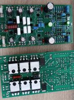
For Sale SARA 2016 (MJL4302A+MJL4281A)

2x SARA 2016 (fully asembled and set bias)

Original thread: https://www.diyaudio.com/community/threads/sara-2016.295317/

dc offset, lower than 10mV
bias 120mA per output pair transistor

Price 100eur + shipping

2x PSU for SARA (partially asembled)

Price 20eur + shipping

Payment: Paypal
Shipping: WorldWide

Attachments

  • 1.jpg
    1.jpg
    548.7 KB · Views: 158
  • 2.jpg
    2.jpg
    519 KB · Views: 155

World's best midrange Blind Testing - Need your help.

***18th july 2015 update***

Thank you to all contributors in my quest for the best midrange drivers.
Got many interesting suggestions and i sure will consider some of them.
Since this thread as drifted to more noise than signal not too long after his beginning, i'll now communicate essentially by private messages; so if you want to get updates on the test, video link, photos, data, etc... you'll need to send me a PM. Thank you and good luck in your future projects!


-------------------------------------

Hi everyone,

We will soon conduct a comparison (blind) test regarding Midrange transducers. Identification type blind test first, then appreciative test...

We have pretty much decided which will be tested among the ''big boys'' (see list below) but we'd like to throw in the game some lower-cost drivers as well... Who knows? An underdog might cause a surprise...

So basically, all drivers will be on an baffle, electronic xover from about 400hz to 7000hz (somewhat the minimum for comfortable listening), EQed and all SPL matched for fair comparisons.

So what i need is some drivers suggestions that can work in these frequencies.


Fyi: here is the list of our best contenders so far:

- Fullrange Voxativ AC-1.6
- ATC SM75-150
- Radian PB950 with Beryllium diaphragm + short horn

In addition, we might consider: Visaton B200, some Supravox, Seas exotic F8, Max fidelity PR65neo, etc...

Please let me know if you have any idea of mid drivers to submit, thank you in advance for your help. Results of the test will be posted later, of course.

-----------

FINAL Pre-selection List update:


Scan-speak 10F/8424G00

Scan-speak 12MU/4731T00

Voxativ AC-1.6

ATC SM75-150

Seas exotic F8

Fostex FF85wk

Vifa/Peerless TG9FD-10-8

Visaton Ti100

Visaton B200

Max Fidelity PR4 neo

Max Fidelity PR65 neo

Alpair 7.3eNc

Airborne FR151 paper cone version

Airborne FR151 wooden cone version


-----------------------

1st August 2015 Notes:

The biggest news (and maybe a little surprising) is: once SPL-matched, in a controlled Blind test environment, the drivers are in fact much more difficult to identify than expected.

For that reason, we will proceed with groups of 4 drivers for each test round. Drivers for each group will be selected for their potential of contrast between each other. Therefore, the identification should be easier and the whole exercise more enjoyable for participants.

Simple Silver Flutes 2 Way

I built a SET tube amp (a Bottlehead SEX 2.1) about a month ago to use in a headphone rig. It sounds so nice that some high(er) efficiency speakers became a must. Looked around for a fitting design, saw the Decware DM945's, read a review, recognized the drivers, and figured I'd take a stab at an homage to them. Here's my disclaimer: I've never heard or even seen the 945's in the real world. Their cabinetry looks great on the website. If you want beautiful, professionally built stuff, I wouldn't hesitate to give Decware a shot. I just wanted to see (and hear) what I could do on my own.

Madisound was really fast at delivering the Silver Flute 8" 4 ohm woofers, the Hivi RT1C-A tweeters, the 3.9 micro F Clarity Caps (SA), and the binding posts. I grabbed some Home Depot 3/4" MDF and poly-fill NU-Foam from Jo-Ann Fabrics.

Here are a couple of pictures and a rough in-room frequency response chart (no particular absolute db scale on the chart).

They're not broken in yet, but they sound pretty good. 🙂

Attachments

  • IMG_0004.jpg
    IMG_0004.jpg
    427.2 KB · Views: 1,566
  • IMG_0006.jpg
    IMG_0006.jpg
    463.2 KB · Views: 1,596
  • IMG_0008.jpg
    IMG_0008.jpg
    161.7 KB · Views: 1,505
  • Like
Reactions: bassman_soundki

Ian Canada streamer - How to lock I2S signal on FifoPi Q7

Hi all, I just built Ian Canada streamer and I have issue of locking I2S signal on FifoPi Q7.

Components used:
1. Pure Pi II
2.Raspberry Pi 4B, 8GB memory
3.FifoPi Q7
4.Transport AES

Prior built I studied all manuals and wached Gabster channel how to build high quality streamer (Gabster call it D5). And was looking forward to test new DIY streamer.

Unfortunately, when I play music via Volumio, there is no signal on coaxial output. FifoPi Q7 I2S Led is off, and lock led is also off.
I went to the manuals (again) several times and can not find
IMG_011412.jpg
IMG_011413.jpg
solution.

Has anybody have the same problem and how did you fix it?

I will appreciate help to resolve this issue.

DIY Class D: Module vs Make

I know this is a subject as old as time, whether module/make or chip/discrete is better in the long run, but I'm asking it in a certain context. Recently I happened upon an article about a comparison of the purifi 1ET400 and the orchard audio starkrimson (https://audioxpress.com/article/fre...d-audio-bosc-and-purifi-audio-eigentakt-eval1). One thing that stuck out to me was the stark contrast in design philosophy. The purifi has clearly had a lot of research put into it with a much more complex design, but the starkrimson held its own just fine. I was wondering if I could get some thoughts on it from the community. From a design perspective, I'm very curious about how they were able to come to the same conclusion, but with very different methodologies.

Bench Testing a Tube Amp Without Tubes

I have a Sherwood S-5500 III integrated tube amplifier that has not been used in decades. My plan is to restore it and have on order new capacitors for the power supply. It has the original tubes which I will remove and test in a tube tester. The tubes are (5) 12AX7 (Telefunken) and (4) 7868 (Sherwood). It is solid state rectified. Before I power it up with a variac and dimb-bulb tester, I will clean all of the controls with contact cleaner because I'm sure they are crunchy.

To avoid damaging the hard to find tubes, can I power it up and measure the power supply voltages without the tubes installed?

Three LM1875 in parallel producing 38W into 8ohm schematics and PCB

I have created this project to try how much power I can extract from LM1875 chip. At first I was thinking about having two in parallel, but then adding a third one was not too hard so I decided why not.

I have assembled two channels and measured them and they are performing very well.
Producing 38.06W into 8 ohm resistor load.
THD+N at 1kHz is 0.0034%, and THD is 0.0028%.

Input signal connector footprint is for Neutrik NCJ6FA-H-0.

Edit: Simplified the gain structure by setting the gain to 10x (20x if you account for the balanced signal) and other minor fixes.

Attachments

  • Screen Shot 2023-03-03 at 9.38.04 PM.png
    Screen Shot 2023-03-03 at 9.38.04 PM.png
    47.1 KB · Views: 496
  • Screen Shot 2023-03-03 at 9.39.23 PM.png
    Screen Shot 2023-03-03 at 9.39.23 PM.png
    46.3 KB · Views: 428
  • Screen Shot 2023-03-03 at 9.37.20 PM.png
    Screen Shot 2023-03-03 at 9.37.20 PM.png
    72.2 KB · Views: 307
  • Screen Shot 2023-03-03 at 9.37.28 PM.png
    Screen Shot 2023-03-03 at 9.37.28 PM.png
    69.6 KB · Views: 416
  • Gerber_PCB-lm1875-lm4562-rev2.0.zip
    Gerber_PCB-lm1875-lm4562-rev2.0.zip
    156.3 KB · Views: 121

Soundstream Rubicon 404 help with trimpots and bench testing

First thank you to this wonderful forum filled with such great posts and people. I'm new here and loving it! I decided to pull an old soundstream rubicon 404 out of 25 years of storage and see if it works so I could install it in my car. I read many articles, including babin perry's website on amp repair and I am so hooked on the topic. I didn't want to go through the trouble of installing the amp in the car first, so decided to bench-test it with a Dell 500W 18A ATX PC power supply. I combined all the 12v rails and the ground rails and used those to feed 12V and Ground to the amp. I also used one 12V power supply wire for the remote and grounded the PC power supply "power on" green lead. To my excitement, the amp turned on. I then wanted to see if it produced the sweet sound I remembered from long ago so I hooked up a set of MB Quart Comp 6.5" mids/tweets to channels 1-2. Played them at a low then medium volume and they sounded just amazing. They had the fullness and depth I remembered and have been lacking in my car audio since. My audio source was my cell phone with a 3.5" audio jack to RCA adapter. I did have to adjust the amp's input level volts but in barely moving the trimpot I encountered some very loud crackling which was so loud I thought I was going to blow the speaker. I therefore decided to make these level adjustments with the amp off and finally had to leave them at 0.3V.

I then repeated the steps but moved my speakers to channels 3-4. Here I did notice that one channel played lower and that one of the two input level volt trimpots didn't feel smooth like the other. I then proceeded to test a sub on these same channels 3-4 bridged and the 6.5's in channels 1-2 and it worked fine. Played it at medium volume so as not to push the amp too hard. The next day I tried the same last setup and for some reason the sub was barely noticeable but the cones was vibrating slightly. Channels 1-2 were fine. I then tried retesting the 6.5" on channels 3-4 and they worked as before.

So I decided to open the amp up and look for anything odd and since the trimpots were acting strange wanted to take a closer look. Upon inspection, I noticed that the left input level trimpot for channel 3-4 was actually not turning. The plastic piece that is attached to the metal shaft is cracked. See attached picture. so the plastic turns but the shaft doesn't. Also I wanted to measure the resistance of each of the trimpots but they are very hard to reach in such tight spaces, especially the center pin. They appear to be from pictures online to be model CA9 by ACP in Spain. Any tips on how to reach the pins to read the resistance. See attached picture. Could this LEFT trimpot be seized and that is why the plastic broke when it was turned? What does everyone recommend for fixing the shaft and the plastic? Should I apply some lubricant on this trimpot and the others as well? If so, would Deoxit F5 do the trick since the CA9 specs say it's a carbon trimpot?

Lastly, during my inspection, I did notice some white marks or stains around the leads for the crossover switch for channels 3-4. See attached picture. Are these anything to be concerned about?

Thank you all for reading my long post. Any and all help is truly appreciated. Also, what are everyone's thoughts on how I'm powering my amp with the ATX power supply? Is this an acceptable power supply for temporary testing? I don't plan on using it long-term this way. Once I can confirm it all works I will then install it in my car.
IMG_0112.jpeg
IMG_0111.jpeg
IMG_0110.jpeg

Boyuurange A50 modding experience

First a big thanks to Stephe for her videos/guides on this A50. There is much work involve making/editing those videos, great work!

I have always wondered about no feedback sound thru my audio journey. Started with Fisher 300/400, progressed to Dynaco, large tube mono blocks, threshold and parasound, most slightly or massively modified. I'd thought it was time to make an effort to sample a SET amplifier. Along comes the Boyuurange A50 mk3 300b. I have followed along Stephe's path, from initial purchase to the full modded version and would like to share my experience. Been doing the audio thing for a long time, almost 50 years. Of course, can't hear as well now. Maybe the reason I don't experience much break-in sensation of parts. However, I've have learned to listen carefully over those years.

My system is made up of sources; Meridian, Oppo modded for 2 channel only, VPI/Dynavector, Tara labs bi-wired Von Schweikert VR-5 HSE(91db). Multiple DIY interconnects (RCA/Eichmann) . Room has been tuned as best I can manage for a non symmetrical arrangement. It very difficult to explain sound as we all experience and prefer a certain presentation. I for one have had a long battle between detail/edgy, warm/blur with the soundstage definition a priority. I'm a low level listener, no 100db level here, and mostly acoustic/folk and light rock.

Stock A50;. I only listen long enough to make sure the unit operated. I only recall the sound was encouraging, and leaning toward my liking which I suppose is "musical", what ever that means to you and me.

Mod #1; As in the videos, I raised the voltages as Stephe advises. Jumper resistor, 5AR4, cap between the chokes, changed 6sn7s to 50s GEs. Now this was a very nice upgrade. I was using the 4 ohm taps to match the impedance of the woofer section of my speakers. The mid/tweeter section is reported to be 8ohms, for an overall 6.5ohm specified impedance. Wow, the ease of the presentation was a nice experience for me. Lacking bass NOT. I can't explain how or why, but musical without having to ramp up volume to get a full picture if you know what I mean. Not perfect, but very surprising, fine detail a little muted. My system, my preference, I could enjoy this for awhile, YMMV.

Cascode mod;. First I have Auricaps(.47 for coupling) and KZ Muse for the 300bs. The first obvious change is the input sensitivity dropping quite a bit. To achieve the same loudness the volume control must be advanced at least a quarter turn or more than previously. Not because loss of power output, just the loss of sensitivity. Overall a cleaner general presentation. Bass also diminished surprisingly but was better defined. The overall presentation had lost it's, say it, it's ease of presentation leaning towards SS. My opinion. What surprised me was the arrival of delicate detail. Can't think of a better explanation, just that. Little delicate details in voices and in the soundstage became apparent. Not forced into the presentation, just floating into the picture.

There is little run-in time on the mods at this time. I will give it an appropriate "break-in". I could be tempted to go back one mod to only raising the voltage. Will see....
  • Like
Reactions: gigantic and aroS3

Tracking down source of noise, 2A3 Amp, goes away when pot turned up

I'm not clear if this is the right place to post this.

I designed and built a 2A3 amp.
6SL7 input tube in SRPP directly coupled (Loftin White) into 2A3 running about 50mA bias, AC heaters.

I have a hum in the right channel with no input connected that goes away once the volume pot (100K, Alps Blue Velvet) reaches about 1/3 volume. To clarify the noise is there from 0 -1/3 at constant volume then quickly fades out and it gone up to full volume.

My first assumption is this has to be a ground issue, but I'm unclear how that could be only on the right channel.
I'm at a bit of a loss as to where to start to try and track this down.
Everything is grounded through a busbar running down the center of the amp.

Any Suggestions

Manipulating Directivity (guide about the fundamental principles)

Several years ago I investigated much time to understand the fundamental principles how to control the directivity of a loudspeaker. I made research using ABEC and some prototypes. The document was written in German so it was limited to a small number of readers compared to world's population. I now translated it to english so that anyone can read it. Please tell me if the translation has any mistakes or is hard to understand.

I hope the document may be helpful. 🙂

Manipulating Directivity

Need help diagnosing and repairing diy speakers

Hi, this is going to be an extreme noob question. I purchased a pair of used/pre built speakers (Jeff Bagby's Solstice, Parts Express) from a person who shipped them to me a few months ago. Unfortunately they seemed to have suffered some damages on the way here, and I'm trying to fix the issues. I'm new to this, and only built one pair before myself that turned out without issues so I'm very lost trying to find the root of the issues.

The tweeter of one isn't playing, and the mid/bass pair of the other isn't playing. The crossover is built on a PCB, and the wires going from input - crossover board - drivers seems ok, I reattached them. There's still no sound from the tweeter, and woofers on the other.

I just bought a multimeter, and I would love to learn how to find the issues. Is it the PCB? Are the drivers damaged? Is there a weak connection somewhere?

How do I begin?

Really appreciate any help here, thanks!

Anyone already produced a usefull modding guide for amps? looking to mod/upgrade a CA azur 650a

Im going to pick up a Cambridge Audio azur 650a in next couple of days.
I would like to mod it and upgrade some of the components.
A comprehensive swap of electrolytics will be 1st thing, starting with C24,25,26,27 c41,42,43,44 currently 8 at 2200uf 50v , scene on a vid somewhere guy replacing caps on a CA A1 and here reduced the number of caps by half, so instead you end up with 4 caps of 4700uf 50v.
I was of the impression that you could up the voltage also?

Has anyone on here modded a azur 650a? or similar?

Suggestions on a postcard

Ta
Paul B

Attachments

  • 650a.jpg
    650a.jpg
    156.9 KB · Views: 187
  • azur trannys.png
    azur trannys.png
    67.7 KB · Views: 122

Tivoli Pal battery problem

I just bought a Tivoli Pal radio from ebay.
The problem with this radio is that it can not charge it's internal battery . I checked the battery pack on the back of the unit and did not see any obvious problems. The unit supplies 14.8-15 volts of DC voltage to the battery pack for charging. But the batteries do not charge!

I took a closer look at the battery pack and noticed that something like a big resistor is connected in series between two batteries (of the six). This component has two legs and a metal body for cooling I suspect. It writes KC100oC 250V 5A. Does anyone know what this is? Maybe this is causing the problem. Can I bypass it?

Many thanks
George

what is this metal clip that holds countersunk screw to chassis?

Hello,

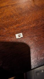
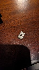
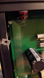
I have a Hagerman Clarinet preamp which is missing one of these metal clips and the corresponding countersunk screw. The clips goes on the chassis, the top panel goes on, a countersunk screw attaches the top panel to chassis via this clip. I'm thinking of selling the preamp and would like to have it all together before I send it off to someone else. Any tips on identifying/acquiring this part would be appreciated.

The chassis is from Lansing, I've reached out to them but yet to hear back.

Cheers,
-Art

Attachments

  • PXL_20231226_232545957.jpg
    PXL_20231226_232545957.jpg
    111.7 KB · Views: 122
  • PXL_20231226_232537793.jpg
    PXL_20231226_232537793.jpg
    98.5 KB · Views: 117
  • PXL_20231226_232522930.jpg
    PXL_20231226_232522930.jpg
    52.1 KB · Views: 123

Carver PM 1.5 speaker protection dials on front face

I recently picked up a carver pm 1.5 and it has speaker protection dials? On the front panel that I don’t see in the mainstream pictures when searching for how to set them. I have only seen two other pictures but they aren’t referenced at all. Can anyone give me any information on these? They are labeled rms output voltage and can set set by a flat head screw driver for delays of 1.5 and 30 seconds. Attaching a picture.
thanks in advance for any help
IMG_2701.jpeg
IMG_2702.jpeg

Crossover slopes within the Schroeder region?

Hi folks-

I bet many of us have systems with a crossover frequency right smack dab in the Schroeder region. Let's chew on that specific problem. Do rules of thumb exist?

Crossover slopes is my main question - do we like a particular "taper" or "feathering" from ray behavior to wave behavior?

I'm thinking more about how you slope the woofers than the mains. I think the mains lowpass is dictated by your power bandwidth needs, and you typically take all the lo end you can get.

On the other hand, you can noodle the subwoofer highpass all day and call it art. But what do the great artists do?

Put another way: Assuming ideal speakers & ideal subs but non-ideal (real) rooms, does an optimum Schroeder transition philosophy reveal itself? Thanks.

Kubelik NOS DAC kits

Updated December 2023

Kubelik NOS DAC kits have now reached the end of their almost 2 1/2 year lifespan and are no longer available. If you'd like a more recent design, have a look at Dorati - https://www.diyaudio.com/community/threads/dorati-nos-dac-kits.387035/ and Abbado II - https://www.diyaudio.com/community/threads/abbado-ii-nos-dac-kits.400326/

Toscanini https://www.diyaudio.com/community/threads/toscanini-nos-dac.389937/ is an enhancement of Kubelik with gerbers, Mouser BoM and schematic freely downloadable but no complete kits.

------------------------------------------------------------------------------------------------------------------------
PM me and be sure to include your payment method and location so I can quote you inclusive of fees and shipping. Kubelik is an upgrade of 'PhiDAC' and keeps the same physical footprint of 81mm * 50mm, the maximum height is 19mm. The design is non-oversampling (i.e. no digital filter on-board) and the input format is I2S (three signal wire) at 44k1/16bits. BCK can be 1.4 or 2.8MHz, no MCK is required. Output is CD standard 2VRMS. There's a digital invert function which allows a balanced output DAC to be made from a pair of Kubeliks. Schematic may be found here : lingDAC - cost effective RBCD multibit DAC design

Preferred payment method is via Wise which typically adds a 2% fee. Our receiving currency is CNY, alternatively USD or Euro. PayPal may also be used, in USD but will attract higher fees, about 16%.

Price for a Kubelik kit : 128RMB (~$17.60)

Shipping is in addition and depends on your location and speed of service. Courier (FedEx, TNT, DHL) typically takes 8 - 10 days and e-packet four to eight weeks. Not all locations can be serviced by e-packet though.

FAQs

What else is needed to turn the built up kit into a fully operational DAC?

First you'll need a well regulated low noise power supply of 20V rated at 100mA or higher. An LM317-based board set to the correct voltage will suffice if you already have an unregulated supply (like a typical wall-wart). I don't recommend switching supplies due to issues with common-mode noise, its very hard to filter out. We can supply an LM317-based board with either DC (for unregulated DC) or AC (for a transformer) input option.

Second you may need a digital interface card. I say 'may' because some digital sources produce I2S directly (like Raspberry Pi, dedicated SDcard players) but most sources will either output USB (like a PC or laptop) or S/PDIF coax (a CD or DVD player) or Toslink. We can supply a card for interfacing one (or more) of those sources to Kubelik's I2S input. A CM6631A-based card for USB input is the premium choice as it operates under 'async USB' which is the lowest jitter. A mid-range alternative is an interface based on an STM32F4 microcontroller - while still low jitter, its output is not as clean on start/stopping as with CM6631A. In the bargain basement dept are the interfaces based on 'adaptive USB' such as CM108 and PCM270X. The S/PDIF board we recommend handles both coax (two inputs) and Toslink. Further, it has a switched I2S input - this can accept I2S from the USB source. A single pole switch acts as source selector, cycling through the inputs. An OLED screen is an option to indicate the selected input. The one drawback with this board is it needs a 5-12V supply, so a pre-regulator is necessary if fed from the DAC's supply. The simple coax/Toslink board needs a regulated 5V PSU.

Third you'll be wanting some output sockets, typically RCAs so you can connect your finished DAC to your amp or preamp. We can supply these and we're working on a PCB to mount them to make outputting Kubelik to your system easier.

Lastly, and this is obviously optional for a DIYer, is a case. We haven't supplied cases in the past because they're so heavy (i.e. expensive to ship).

USB CM6631A card examples : https://www.aliexpress.com/item/32874113831.htmlwww.aliexpress.com/item/1005004083748180.html
USB STM32 card example : https://www.aliexpress.com/item/1005003632369097.html
USB PCM270X card example : https://www.aliexpress.com/item/4000141799137.html
Multi-input S/PDIF card : https://www.aliexpress.com/item/1005002923079600.html
Coax/Toslink S/PDIF card : https://www.aliexpress.com/item/1005002772984954.html

Do I need special tools to build and test my Kubelik kit?

You'll need some fine diameter solder (0.3mm is recommended), a temperature controlled soldering iron with a fine bit and a pair of tweezers. A magnifier comes in very handy but that depends on your eyesight. Desoldering braid is helpful for correcting mistakes. If you've never soldered SMD before then maybe Kubelik will be too challenging for a first project as there are more than a hundred parts. However none of them are microscopic (the smallest is 0805) and none of the ICs has pins closer together than 1.27mm. For testing you'll need a DMM (digital multimeter).


What's supplied in the kit?

There's a picture directly below of the contents : the bare PCB plus all the components that mount on it (resistors, caps, inductors, LED, ICs etc.). Given that 0805 sized components are incredibly easy to lose, we include a spare or two for each value. Input, output and power are supplied via 4pin Molex-style headers, we supply the mating half with crimped wires to these too.


What, if anything, is unique about Kubelik's design?

Commercial NOS DACs typically have minimal filtering after the DAC chip itself. Kubelik has two kinds of filters resulting in a 5th order overall lowpass response - a 3rd order passive filter prior to I/V and a 2nd order active filter afterwards. The passive filter prior to any active stage improves subjective dynamics - it means the I/V opamp no longer 'sees' a step waveform out of the DAC chip, rather a continuous signal. The active filter provides 'NOS droop' compensation - meaning you get a flat frequency response to around 17kHz whereas a typical (not every) NOS DAC has roll-off approaching 3dB by 20kHz. It also has headroom to cope with 'intersample overs' which may occur on some heavily compressed recordings. Meaning it won't clip its output no matter what digital input you give it. Opamps are used but their outputs are buffered with discrete transistors as I've found this results in improved instrumental separation when the music gets very 'busy'. Kubelik's DAC chips are 'multibit' but they're not strictly speaking 'R2R' as internally they use no resistors. Instead capacitors are used as elements in the DAC which have their charge constantly refreshed (similar to the DRAM in your computer) to compensate for any drift.


Here's the build and test guide for Kubelik - lingDAC - cost effective RBCD multibit DAC design

Update : The two older versions of the stuffing guide had various errors, here is the up to date version : https://www.diyaudio.com/community/...-rbcd-multibit-dac-design.324933/post-6889095

Attachments

  • Kubelik_kit.jpg
    Kubelik_kit.jpg
    118.9 KB · Views: 2,554
  • Kubelikr3_builtup.jpg
    Kubelikr3_builtup.jpg
    167.8 KB · Views: 2,586

Pearl 3 Cartridge Thread

Thought that it might be useful to have this as a container for things cartridge related. To start off here is a link to Part 1 of a post by Michael Fremer re. cartridge azimuth.

In regards to measuring azimuth I mentioned a little box that Bob Graham markets which I believe takes the left/right channel sums them while inverting 1 channel. Then by playing a mono recording, without a lot of high frequency content, you can adjust azimuth till you get maximum cancellation. Please someone chime in if I got this wrong.

5Ц4С replacement with solid state?

What is the solution to this problem without adding a whole lot of complexity to the power supply?

1) I want to replace the Russian 5Ц4С with solid state rectification in this power supply, and I don't want to jack up the voltage. The voltage drop across the rectifier tube is about 45 volts, correct? How do I get rid of the excess voltage from solid state rectification without harming the power supply performance and preferably improving it? If I can use solid state and get a performance improvement at the same time, great!
2) I also need to drop a little more voltage because the transformer is rated for 110V and I have 120V from the wall. It's a single-ended, 6H8C - EL34 amplifier, and I don't know what the current draw for that might be. The choke is rated at 200mA. Specifications call for 310V and 285V out as shown. Wall voltage is 120VAC going into a transformer designed for 110VAC.

3) If I decide to use tube rectification, what is the expected lifespan in hours for a longer life replacement tube, and which tube type to use? 5Ц4С is rated only 500 hours. I really want the convenience of solid state like my other three tube amps. Only 500 hours is a real pain, and the cost adds up as I put a lot of hours on my system.

I can make simple changes, as the amplifier hasn't been built yet, but I do not want to add a whole lot of complexity to this schematic. There has to be some reasonable solution.

Let's not discuss the merits of or problems with the audio circuit here please. Let's save that for later if I build this kit. Let's focus on the power supply as that is all that matters right now. Power supply design is a subject of its own and a critical skill, so that's why I started this thread.


1700459284870.png


1700460962604.png


schematic raw.jpg

That time I gave a toaster an exorcism

Dateline: Late 70's. My first job in broadcast, a 3KW FM/5KW AM radio station.

The station was built on farmland but the suburbs had grown to surround it. One day I got a call from a very upset but very sweet and very old woman. She was mad that she couldn't NOT hear our station. She had a lot to say so I heard her out, and it turned out she was convinced her toaster was possessed because it was speaking to her.

She lived at the back corner of our property. I had to go see for myself.

The AM station was a four tower array with different daytime / nighttime patterns. Both patterns had a lobe pointed straight through her house. The closest tower to her was all of three hundred feet away.

I was met with the specter of a vintage chrome toaster singing Cher's "Gypsies, Tramps and Thieves", clearly and unambiguously, directly to me. It. Was. Haunting. The lady was right!

Now I don't know if Satan exists or not but I was damn sure he wasn't gonna use my radio station as his unholy vessel. And I can't speak for Cher's relationship with the evil one but I suspect she was an innocent in all of this. Then the toaster told me the weather.

I was fresh out of garlic and crucifixes so I did some LC thing on the powerline and cleansed all the souls involved. Sadly it was before the movie Poltergeist so I didn't think to say "this house is clean".

Marantz PM6005 little/no sound from right channel intermittently

Hello,

Was hoping someone could help me figure out what might be the problem.

I have a Marantz pm6005 that I have stopped using because the right channel would produce no sound or almost no sound. Sometimes if I turned the volume all the way up I could barely hear it. I swapped the speaker cables, tried different sources (digital/analog), different speaker outputs (A,B), cleaned the volume pot, and also replaced the volume pot.

But the problem persisted. Sometimes it would work for a few hours or days then randomly it would stop.

About 1.5 years ago I took it to a repair shop and they kept it for 3 weeks to see if they could reproduce the problem and, according to them, it never happened while they had it. I picked it up and that same day the problem popped up in my system. At this point I gave up on it and started to use a different amp.

I have some time now to really look at it again and would like to be able to locate the problem and fix it if possible, however I'm not sure how to approach this.

Any help would be appreciated.

Regards,
R

Full range speaker for arcade build?

Full size MAME Arcade cabinet build, that will also double as playing blu-ray movies. Started with intent to repurpose very old auto components/amp, but I need to pivot to using full range, and a much more efficient amplifier/speakers. I do not want to have a powered sub, so will probably need at least a 4-5 inch speaker. Will also likely be powered by a not yet acquired simple 2-channel amp board, like the Dayton KAB-250v4 2 X 50W

Any suggestions on a good full range that would have a decent amount of bass? I have been out of the building game for some years now, and never really tried full range designs before. I will be putting a new baffle panel, so will not need to use existing. I also would not be averse to constructing a sealed enclosure behine the baffle for each driver, if that turns out to be necessary to get proper bass response.

I know the HiVi B4N's could be an option, but haven't any experience with using them full range, without a tweeter.

2.jpg


1.jpg


3.jpg

Eve Audio Studio Monitor Problem

Hi All,
Please listen to the recorded mp3 file : I play a pure sine wave (852Hz) . As I turn the level up, an strange noise apears. I have no clue where the problem is. My monitor is SC307 which uses SMPS , DSP and Class D amplification. Any help would be appreciated
2023-01-31-20-28-12-084.jpg
2023-01-31-20-28-47-156.jpg
2023-01-31-20-29-13-315.jpg

Attachments

Simple HEC Amplifier 24VDC

HEC amplifier topology created by Bob Cordell. I'm interested to make simulation using this topology.
It used 24VDC PSU and OITPC compensation that created by Dadod.
Output stage is simple using double emitter follower with driver bootstrapped. Using small transistor in driver,
make loop gain higher because their high hFE.

Any suggestion are welcome.

Attachments

  • HEC45_Loopgain.png
    HEC45_Loopgain.png
    57.8 KB · Views: 676
  • HEC45_clip_20kHz_8Ohm.png
    HEC45_clip_20kHz_8Ohm.png
    49 KB · Views: 333
  • HEC45_THD20kHz_8Ohm.png
    HEC45_THD20kHz_8Ohm.png
    62.3 KB · Views: 668
  • HEC45_SCHsim.png
    HEC45_SCHsim.png
    44 KB · Views: 726
Projects by fanatics, for fanatics
Get answers and advice for everyone wanting to learn the art of audio.
Join the Community
507,677
Members
7,883,819
Messages

Filter

Forum Statistics

Threads
406,008
Messages
7,883,819
Members
507,677
Latest member
Purwoko