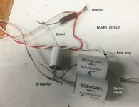
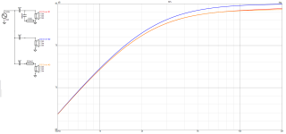
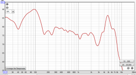
I added Raal 70-20r tweeters to my speakers based on a design by Roy Johnsons. I got the specs for the tweeter side of the crossover from Roy and a Zobel design from the owner of Raal. I decided recently to make some measurements. The HF measurements were not so great with a dip at 3000 hz and a big spike at 5000 hz. So I decided to make some changes starting with the Zobel. Measurements are in-room but it is a large room with high ceilings so reflections are not a huge factor.
in the process I measured just the woofer and found that the dip and spke were both present just with the subwoofer. So I am baffled (no pun intended) as to what might cause the woofer to not have a rolloff. It is a simple crossover with a capacitor/coil and resistor for the lowpass and 2.2 uf cap equivalent on the tweeter, Zobel is .68 uf cap and 6.8 resistor.
I cannot see any issues in the woofer section of the crossover. Any idea why I am getting a bit spike with just the woofer, no tweeter connected. see photos. I am very amatuer at all this so I need some help.
You say the woofer has this (you haven't included the individual curves on your plot), it could be coincidence, or it could be in your common circuitry?
Have you simulated your baffles or done polar measurements of them?
Have you simulated your baffles or done polar measurements of them?
It would also help if you included the schematic for your crossover and units on the y-axis of your frequency response plot.
If there's a possibility that your physical crossover layout doesn't match the schematic, a picture of the physical crossover might help as well. Even with experience, it's pretty easy to make a mistake when wiring a new crossover the first time.
If there's a possibility that your physical crossover layout doesn't match the schematic, a picture of the physical crossover might help as well. Even with experience, it's pretty easy to make a mistake when wiring a new crossover the first time.
Thanks - I really appreciate the help. I don't know that much about xovers so could have easily done something wrong.
I thought schematic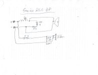
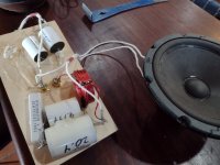 would be needed. Here is a schematic and picture. To me it looks like a RLC Band pass filter with additional caps for the high pass. But I don't understand why the woofer is connected before the caps rather than after.
I thought schematic


 would be needed. Here is a schematic and picture. To me it looks like a RLC Band pass filter with additional caps for the high pass. But I don't understand why the woofer is connected before the caps rather than after.
a bit more explanation - the handrawn schematic is just what is physically there. I don't have an original schematic. I took the original crossover, removed the high pass filter section for the tweeter and added the components suggested by the designer (shown in the photo)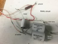 . I didn't change anything in the low pass section. My assumption is the designer knew what he intended and designed it accordingly.
 . I didn't change anything in the low pass section. My assumption is the designer knew what he intended and designed it accordingly.
Your inductor looks small to be 4 mH (I think that's what your schematic says). Can you confirm its actual and intended values?
Your capacitors in both legs are in parallel physically, but shown as series in your schematic. In parallel, capacitor values add.
On the woofer circuit, the RC seems more like a frequency response/slope modifier, given the values. In practice, a lot of this stuff kind of blends together, so it's hard to decide what's an impedance equalizer, modified 6 dB/octave crossover, modified 12 dB/octave crossover, etc.
Can you do a nearfield measurement of the woofer? This is typically done with the microphone about 1/4 inch away from the cone. Keeping everything physically the same and repeating the measurement without the crossover on the woofer would also be good. The near-field method pushes all the room reflections, background noise, and other drivers way down relatively, so helps show more of what the woofer is really up to. It's not accurate at higher frequencies but can still be useful diagnostically.
Looks can be deceiving especially when a schematic can be drawn to appear different, even when it isn't.why the woofer is connected before the caps rather than after.
Electrically it is neither before or after, the woofer is in parallel with the RC branch.
M - I really wondered about the caps being parallel - They are indicated to be in series in the photo of the Raal circuit. I can't imagine Roy making such a huge blunder but he was sadly dying of cancer so . . .
Unfortunately, I do not have the specs on the inductor, that was just a pencil mistake, not intended to be a 4. I only have a simple ohm/volt meter so don't think I can measure the inductance.
I am taking the drivers off the crossover and measuring separately. I'll do the woofer with xover and without and see what it looks like. I am measuring everything out of the cabinet and with mic about an inch away.
I did measure the tweeter separately already, with just the caps. I had the same drop out at 6k with a bump slightly higher. the Zobel doesn't make any difference at all in the measurement. I think I'll try rewiring the caps in series and see if that is what was intended.
thanks for you help so far. I'll keep you posted and put up some measurements when I get something.
That's an issue, if you're saying you're measuring frequency response with the woofer out of the cabinet. That will not give a reasonable representation of the driver's performance in the enclosure.measuring everything out of the cabinet
What Raal circuit are you referring to? According to this, the tweeter is typically used with a single series capacitor of 4.7-10 µF. If you put them in series, you will move the high-pass up pretty high (something like 8-10 kHz).I really wondered about the caps being parallel - They are indicated to be in series in the photo of the Raal circuit.
https://www.madisoundspeakerstore.com/ribbon-tweeters/raal-70-20xr-am-extended-range-ribbon-tweeter/
I think my issues are in the low pass portion of the xover. Does not seem to be providing any hf rolloff.
WIth the two ends of the 5 & 4 uf caps twisted together, they are in parallel, not series. It would be stupid to put a 5 & 4 in series, that would leave a total capacitance of about 2.1 uf which would be a lot cheaper bought direct at that value. In parallel 5 + 4 equals 9 uf which is a expensive value that cannot be bought from stock.
The inductor series the woofer gives a 6 db/octave towards the highs at some value, and the caps parallel the woofer, with a series resistor, roll off the woofer response another 6 db/octave towards the highs. I don't see the 15 ohm resistor in your schematic in the picture of the parts laying on the table.
Caps series the tweeter roll off the lows at some value, 6 db/octave towards 100.
What are the DC resistances of the tweeter & woofer? Use a known resistor value under 10 ohms to calibrate your meter results, resistances under 10 depend a lot on the battery and how hard the probes are pushed on the terminals. Speaker impedance is approximately equal to 4/3 speaker resistance.
Last edited:
I appreciate that, but it helps to make sure everything is correct/understood before random changes are introduced. Too many chances for error to be the overriding theme of trial and erroring a crossover without a decent understanding of how the pieces are being used, how to properly measure the acoustic result, etc.I think my issues are in the low pass portion of the xover
Part of the challenge of helping from a distance is understanding what someone really has in front of them and what level of experience they are working with across what is necessarily a pretty broad swath of methods.
The lower woofer resonance is likely to be a room resonance (or bad box design), play with placement in the room to alter it.
The high frequency resonances are cone breakup, get rid of the unnecessary Zobel and use a higher order crossover for the woofer.
I say 'unnecessary' because simply tweaking the values in a 2nd order xover will have the same effect, with less cost.
The high frequency resonances are cone breakup, get rid of the unnecessary Zobel and use a higher order crossover for the woofer.
I say 'unnecessary' because simply tweaking the values in a 2nd order xover will have the same effect, with less cost.
thanks so much for the help - I am hopefully learning a lot - I did read Bagby's white paper so learned a bit about measuring. I am using REW with a calibrated cardioid mic (Rode NT1A).
so what I have gotten so far is:
I need better in box measurements - I have attached graphs of near and far (20 in)
I eliminated the Zobel as it didn't seem to make a difference.
Woofer measures at 4 ohms (3.9) so impedance would be 5.2 - I am not sure about Ribbons, can't read resistance - I think they are wound at around 7. crossover point is around 1800 (recommended by Raal)
When I look at the charts, it seems that the tweeter circuit is fine with 9 uf cap value, no Zobel.
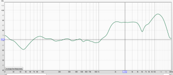
Tweeter near field
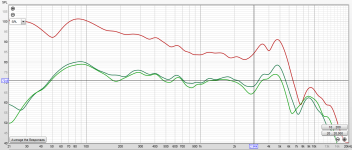
Woofer near (red) far Green
woofer needs to roll off at a lower frequency, currently is way too high - probably designed for the previous tweeter and I never got new specs from Roy.
So what is the best way to modify the current low pass to move crossover point down to appropriate match for tweeter?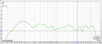
speaker near field (mic about center between woofer and tweeter.
so what I have gotten so far is:
I need better in box measurements - I have attached graphs of near and far (20 in)
I eliminated the Zobel as it didn't seem to make a difference.
Woofer measures at 4 ohms (3.9) so impedance would be 5.2 - I am not sure about Ribbons, can't read resistance - I think they are wound at around 7. crossover point is around 1800 (recommended by Raal)
When I look at the charts, it seems that the tweeter circuit is fine with 9 uf cap value, no Zobel.

Tweeter near field

Woofer near (red) far Green
woofer needs to roll off at a lower frequency, currently is way too high - probably designed for the previous tweeter and I never got new specs from Roy.
So what is the best way to modify the current low pass to move crossover point down to appropriate match for tweeter?

speaker near field (mic about center between woofer and tweeter.
To wind down 5 ohm woofer 12 db/octave at 1500, butterworth, series inductor .7 mh parallel C 20 uf. Try 58 turns #20 wire on a 1" diameter core. Weems figure 8.3. To save money on caps, if amp is <100 watts can use 100 v caps instead of 200. First pass can be cheapo mylar caps but premium systems polyprophylene sounds better.So what is the best way to modify the current low pass to move crossover point down to appropriate match for
Last edited:
Ok, so I am going to experiment - sticking with first order crossover, I will:
Leave tweaters as they are with 1800 hz crossover point (9 uf cap), I am still wondering if Roy meant 2.2 but agree a dumb solution would be to put two expensive caps in series.
change woofer to .63 mH inductor, eliminate 29 uf with 15 ohm resistor to see effects.
experiment with .63, .70 and .45 inductor to see what low frequency roll off is, and adjust tweeter caps as needed to move crossover frequency.
The reason I am staying with 1st order is this was Roy's original design (the whole phase coherent thing) notice speakers have adjustable tweeter distance, I just don't understand if I need the additional cap/resistor circuitry.
I am deciding this based on the response curve of the woofer (fairly decent up to 2 khz) and the fact that Raal suggests a single capacitor circuit with cutoff at 1800 hz.
please let me know if I am way off base here (or way off bass 🙂)
Thanks again - I feel like I am gaining some understanding or enough knowledge to be dangerous.
Well the bad news is that my mic calibration file is completely bogus. I was hoping to use the Rode mics I already have but can't get a decent calibration file for them.
the good news is that my frequency response is not nearly as bad as indicated using the cal file. without the cal file, the woofer response is pretty flat up to 6k. I have not re-measured the tweeter.
so I ordered the correct microphone and will redo all measurements and start over.
the good news is that my frequency response is not nearly as bad as indicated using the cal file. without the cal file, the woofer response is pretty flat up to 6k. I have not re-measured the tweeter.
so I ordered the correct microphone and will redo all measurements and start over.
so I got the correct measurement microphone and calibration file - I have very good flat response with Raal using 12uF capacitor. Roll off is right at 1800 hz where I would hope it would be.
The woofer is flat up until 2000 hz; and then gets whacky so I tried .4, .63. and .7mH inductors - none of them make any difference in woofer response measured nearfield.
Can someone please help me understand what is going on? To implement a 1st order crossover, don't I just need the appropriate inductor value in series with the woofer? What am I missing. Even with the lack of woofer roll-off the combined response is not terrible but there are some phase issues.
I would really appreciate some help here! thanks;
- Home
- Loudspeakers
- Multi-Way
- Help Tweaking Crossover
