KEF NT25 tweeter ferrofluid replacement glue question

Hi everyone,

I am going to be undertaking this procedure on my Kef Reference 3.2s and I could do with some reassurance!

I am just wondering what sort of glue I need to use to join the plastic dust cap/surround to the metal magnet back together once I have replaced the fluid?

Is superglue / Gorilla glue too strong?

For reference it's the two pieces shown here: https://audiokarma.org/forums/index...-pictures-and-a-question.709897/post-16063194

Thanks very much!

  • Locked
For Sale Heyboer Power Transformer 400-325-250-0

Used Power transformer originally wound for the Guinivere project about 20 years ago and still functioning as:
262-340-422-0 5V@3A 6.3V@3A

Leads are all cut but even the very short Primary long enough to splice. There is EAR SD-40 attached to the base and the bolts are brass..

USPS Ground Advantage estimates at $25 so that is the flat rate you will pay

Payment by US Postal money order only, sold as is

PT2.jpg

Aerofara mini/musicPC W10 Pro, miniDSP Flex Digital, Volumio Primo

As the title says. I no longer need these and want to give them a new home.

Asking:
euro 100 for the Aerofara
euro 100 for the Volumio Primo HiFi Edition - sold
euro 100 for the miniDSP (note: the label on the back says Dirac but this is without a Dirac license!) - sold

All come with original power adapter.

The Aerofara comes with W10 installed and has the following connections on the rear and sides:
3 x USB-3, VGA, HDMI, SD card slot, Ethernet, Headphone.
Read the review here: https://www.cnx-software.com/2022/0...eleron-n5105-mini-pc-windows-11-ubuntu-20-04/

I am located in Belgium, will charge shipping at-cost.
Ask me for a binding shipping estimate to your location.

If you are desperate, make me an offer I can't resist ;-)

Jan

Attachments

  • aerofara.jpg
    aerofara.jpg
    269.6 KB · Views: 97
  • miniDSP Flex Digital front.jpg
    miniDSP Flex Digital front.jpg
    212.1 KB · Views: 102
  • miniDSP Flex Digital rear.jpg
    miniDSP Flex Digital rear.jpg
    260.5 KB · Views: 93
  • Volumio Primo front.jpg
    Volumio Primo front.jpg
    119.9 KB · Views: 103
  • Volumio Primo rear.jpg
    Volumio Primo rear.jpg
    219.5 KB · Views: 102

Could someone explain this Leakage Current rating for this filter cap? (see in description)

I'm looking for replacement filter capacitors for my amp and found a really good one, but by the spec sheet I can't tell the actual leakage current rating. Is 3 milli amps a maximum? Because if it was the actual one, then it's way too high. Here's the line from the data sheet:

Leakage Current.png


Here's the full document: Datasheet

I would appreciate if someone could explain it to me and possibly tell the actual rating.

Evidence of Driver Break-In Captured

I was starting on a new speaker design using a Fostex woofer from their NX6A powered monitor. This 6.5in driver has a unique pinched cone and wrinkled surround, similar to the Purifi woofers. I got the bare drivers about 3 years ago for a blowout sale ($15 IIRC). Since these are not currently in production anymore, this speaker design would be fully open source and was being made for my personal DIY pet project (not commercial). I started to describe it here. Anyhow, after installing the driver in suitable cabinet that I had lying around, I proceeded to make some measurements to collect the FRD files needed to simulate the XO. The speaker looks like this. Tthe cabinet was an early prototype for another woofer and tweeter so none of the cutouts had rebates or cutouts that fit the NX6A woofer and a Dayton AMT2-4 tweeter that I had planned on using. So, I had to make some 3D printed adapters for the tweeter and for the woofer, I settled for surface (non-flush) mounting and will live with it.
1708572548824.png


So after putting the speaker with drivers installed and I took the initial sweep, I was shocked at the high level of distortion from 150Hz to 4khz, especially the 3rd and 5th harmonic distortion (note that distortion levels in legend refer to distortion at cursor location - which I am not sure if I kept constant - I would go by the vertical dB axis value though, you can see distortion peak at 64dB :
NX6A-Breakin-Dist-01.jpg


I spent the next hour trying to see if there was a setup issue, or something wrong with the electronics, wires, frame rattle, etc. All to no avail. But what I did notice was that the level of distortion was slowly going down with each sweep. I was playing with removing the vent tube, plugging the tube with stuffing, or leaving the tube in, thinking it might have something to do with it. Here are subsequent sweeps and you can see each one, the level of THD goes down a bit. the sweeps are chirped sound lasting about 5 seconds.

Number 2 (vent tube removed):
NX6A-Breakin-Dist-02.jpg


Number 3 (with vent tube back in):
NX6A-Breakin-Dist-03.jpg


NX6A-Breakin-Dist-04.jpg


Seeing the THD go down a bit, I tried running 45Hz at about 2.8vrms for 1 min to see if this loosened up the suspension: And it sure did!
NX6A-Breakin-Dist-05.jpg


So I tried leaving the 45Hz on for 60 minutes - distortion at 300Hz went down to about 34dB an apprximate 30 dB improvement!
NX6A-Breakin-Dist-06.jpg


I wanted to be sure it was not caused by the vent or lack of one or by plugging the vent, so I took a few more sweeps in different configs and now the distortion remained low:
NX6A-Breakin-Dist-07.jpg


NX6A-Breakin-Dist-08.jpg


Here are all the responses overlaid and you can see the effect of the vent/no vent/stuffed vent:
NX6A-Breakin-Study-Freq-All.jpg


So I have left the speaker on playing music continuously for 3 days now, hoping that maybe I can eek out a bit more improvement. I have not checked again yet, but it seems the majority of break-in for this deiver occurred in the first hour playing some bass to really move the cone.

Here is the Wago plank crossover that I ended up with:
1708573612790.png


Measured response:

1708573650765.png


Overall distortion at 2.0Vrms and microphone 0.5m away:
1708573682010.png


Measured phase variation:
1708573730467.png


Pretty clean now. It sounds quite nice. But I think I have seen it with my own eyes and instrumentation - the real effect of driver suspension break-in on harmonic distortion. Has anyone else measured something similar? You can listen to the current speaker here.

For Sale Germany/Berlin: Dayton RS225-8, Faital HF108, active XO, enclosures

Hello,
I know putting this out here, chances are slim.
This is ideally for pickup as a whole set. (~near Berlin)
If you are interested let me know if you want the whole or just parts of it
and we will work out a price that will be more than fair.

I already built test enclosures for this (2-way, ~40l, sealed so far) out of 18mm birch ply.
HF108 is used but working.
RS225-8 are brand new in box.

Optionally in addition to the speakers set (2xenclosure, 2xHF108, 2xRS225-8 & connectors)
I can offer an active XO and amps too if there is interest:
Minidsp 2x4, UMIK-1 USB microphone, two Ayima A04 and input selector unit with PGA2310.
I can also include a Vicor power supply 24V/10A.

Best regards from Fürstenwalde
Jens

camillaDSP: How to monitor and control audio channel mapping to HDMI?

In CDSP I am mixing 2 stereo channels to 8 (2x4) channels out to hdmi:vc4hdmi0. I expected that the channel mapping would auto-magically follow the CEA-861 CA=0x13 mapping. I.e. [FL, FR, LFE, FC, RL, RR, RLC, RRC].

In practice the CDSP outputs do not appear to follow this mapping at all. Based on listening to the AVR outputs they are currently mapped [RL, RR, RLC, RRC, FL, FR, LFE, FC]. I also suspect that this mapping actually changes in some sessions, but I am not yet sure what conditions cause a change. This is of particular concern for speaker x-over applications.

In contrast, the speaker-test application consistantly conforms to CEA-861 CA=0x13 (assuming the numbers it displays really are it's output channel indices.).

I did notice that the alsa Loopback device has auto-magically acquired several associated surroundXX plugs, but the hdmi devices have not. - this might be significant, or not.

Config: rpi4b, bookworm, os-lite, pyCamillaDSP 2.0.2 Backend 2.0.1, Onkyo TX-SR875 AVR

For Sale GU-48 ( 833A ) old NOS tubes

I would like to offer OLD NOS GU-48 tubes. They are mentioned in this my thread

https://www.diyaudio.com/forums/tubes-valves/365401-tube-amplifiers-pmc-eb1i-speakers.html

Before this 833A project, I have collected a lot of GU-48 tubes from russian traders. They there all in sealed original boxes. During the 833A project, I assembled a high voltage test unit, and heated up all the tubes with applying 1700-1900V voltages to plates. All tubes were stable in plate current after few minutes of heating, that is absolutely wonderful result for big tubes produced in 1972-1974 year. They are very good and reliable stuff, and I could select even "matched" pairs and quards, based on the one-parameter testing results.
I could sell up to 20pcs of these tubes, packed as pairs or as quards, with good packing quality. I want 125usd/pcs, plus shipment.

Attachments

  • GU48 boxes.jpg
    GU48 boxes.jpg
    346.1 KB · Views: 653
  • GU48 tubes.jpg
    GU48 tubes.jpg
    426.3 KB · Views: 739
  • GU48 tube Logotype.jpg
    GU48 tube Logotype.jpg
    384.3 KB · Views: 727
  • gu-48 datasheet.pdf
    gu-48 datasheet.pdf
    64.6 KB · Views: 223

Exactpower EP-15A Voltage Adjustment?

I recently got one of these back up and running (replaced the group of four small caps), but the output voltage is a little high at 122-123V (instead of 120V +/- 1V).

There are three trimpots inside, and I am guessing that one or all are required to adjust the output voltage.

Before I start experimenting, does anyone know what each of these trimpots adjust?

Attachments

  • IMG_3194.jpg
    IMG_3194.jpg
    961.1 KB · Views: 125

Burson V6 Vivid Review

I am posting this review of Burson V6 in the solid state section because although its an Operational Amplifier but it is also a discrete OP AMP.

Couple of months back John Burson offered to send Burson Discrete Op Amps and I had to d a review in return, as my sci fi novel are in the final stages of completion I utilized my humorous acumen to review Burson V6 Vivid, so here goes:


In my recent escapade with the venerable miro1360 AD1865 DAC, enhanced by the magnificent Burson V6 Vivid discrete operational amplifier, I uncovered a treasure trove of auditory delights! Allow me to regale you with the saga!

Installation Extravaganza:

The Burson V6 Vivid's insertion was akin to a masterful swordplay manouver in a medieval epic - seamless and fitting like a bespoke suit. Kudos to Burson for making compatibility feel like a breeze on a sun-drenched meadow!

The Grand Sonic Melee:

Let's set the stage for our contenders: LME49720HA, LM4562, AD8620, OPA2134, and OPA2604 - each a valiant warrior in their own right. The Burson V6 Vivid, brimming with confidence, danced through this sonic battlefield, challenging each foe with unbridled enthusiasm.


Comparative Table:


Operational AmplifierPerformance Rating (Out of 10)Verdict
Burson V6 Vivid9.8Majestic!
LME49720HA9.7A Worthy Adversary!
LM45629.4Respectable Showing!
AD86209.0Sturdy Effort!
OPA21348.8Admirable Attempt!
OPA26048.8Valiant Fight!


The Burson V6 Vivid asserted its dominance, leaving the LM4562 in awe, coaxing the AD8620 into joyous sobs, and nudging the OPA2134 to strive for more.

Then came the grand showdown with the LME49720HA - a titan, a legend. These two clashed in a battle that resonated through the ages. The Burson emerged triumphant, but it was a contest that left no doubt about the LME49720HA's legendary status.

A Symphony of Sonic Splendor:

The Burson V6 Vivid, the maestro of this orchestra, conducted with finesse and flair. Highs soared like eagles, mids enveloped in a warm embrace, and bass reverberated like the heartbeat of a dragon. It was a crescendo of sonic ecstasy, painting vivid landscapes in the theater of my mind.

The Rendezvous with Spotify:

Connecting the DAC to my trusty iPad via USB and XMOS interface was a tryst made in audio heaven. Spotify, in its highest quality garb, serenaded my senses. It was as if I could hear the artists' very souls, etched into every note and chord.

A Time-Traveling Serenade:

Ah, but the true marvel came when the USB cable embraced my laptop, where audio was set at 24-bit and a resplendent 192 kHz. FLAC files from various artists graced my ears, transcending the boundaries of time and space.

Richard Marx's velvety croon swept me back to the golden days of heartfelt ballads. Celine Dion's powerful vocals carried me to a realm where emotions knew no bounds. Rahat Fateh Ali Khan's soul-stirring songs transported me to distant lands, echoing through centuries of musical tradition. And Pankaj Udhas, with his mellifluous ghazals, serenaded me through a journey of poetic elegance.

In each note, I felt the pulse of history, the heartbeat of artistry, and the essence of human expression. The Burson V6 Vivid had transformed my listening space into a time machine, and I was the fortunate traveler.

In the end, the Burson V6 Vivid left me spellbound. It's more than an amplifier; it's a conduit to a musical universe. While the LME49720HA put up a gallant fight, the V6 Vivid emerged as the resplendent victor, staking its claim as a force to be reckoned with.

Now on a serious note, listening to Music is more than just a few tests about spectrum, frequency response, distortion etc; to me it is a matter of personal preference, the audio setup, the room acoustics and a few other qualitative things, for me Bursons needed about a week’s burn-in time after that they really came alive. LME49720HA with heatsink after burn-in period is much too good. I have Burson v4 as well but I found V6 much better that the earlier versions.

I intend to put the Burson in my version of Bugle 3 clone, but that’s for later. Also I intend to pit it against @Vunce 's IV stage for DAC, that will happen when my TDA1541 DAC is ready, which is currently waiting for WIMA capacitors to arrive.

@John Burson , @miro1360

Here is how my test bed looks like:

20230908_172825.jpg
20230908_172844.jpg
  • Like
Reactions: lineup

Firstwatt F1J

Nelson appears to have re-spun the original Firstwatt beast, designed as current amplifier, good for fullrange speakers. It got good reviews originally, but not often seen (IMO) as a diy project. I think it's worth discussing here.

The addition of the F1J with SiC JFet's replacing the IRFP240 output devices may breath new life into the circuit. A single stage amp I think as refered as 'the truth machine'.

Here is what Papa says.. (Paraphrased)
The F1J is an update to the F1 where the two gain Mosfet transistors have been replaced by new state-of-the-art power Jfet devices. In addition, there have been changes to several resistor values and removal of the input zener protection diodes.
You may notice that the F1J also has approximately 1.5 dB more gain. This is because the Jfets have a higher transconductance figure that the original Mosfets.

There is another factor as well, which is that the F1J has a lower input impedance than the F1- approximately 30 Kohm balanced and 15 Kohm single-ended. The modifications that help achieve this bandwidth take advantage of lower impedances, so the F1J is recommended for use with preamps with ordinary to low output resistance – tube preamps without cathode followers will work but will not reap as much benefit at high frequencies.

This caveat aside, the F1J delivers a dramatic improvement in current-source amplification. I have often ventured the opinion that improvements in measured performance in simple Class A circuits (particularly with no feedback) usually have the best correlation between what you measure and what you hear, and the F1J bears this out. I think it sounds about twice as good, and I feel certain that you will experience the same remarkable improvements.

Maybe Nelson will share some details for those with the amp, maybe not 😛

Help me understand this circuit. Aragon 47k/Acurus P10 Phono Stage

Hello!
Hoping you all can help me understand this circuit and what/where are the critical components in the signal path. This is a 90's Aragon 47k/Acurus P10 phono stage one channel shown in the schematic. My goal is 'simple project' to practice my soldering skills, to try some resistor upgrades, and see what can be can be gained.
I understand R1-R6 are loading resistors, R10 is the input resistor, and Q1, Q2, Q3, and Q4 are transistors. I'm confused how the signal flow seems to split between C9 & C8 (which seem to implement the RiAA curve) and Q5 & Q6. I think R21 & R20 are the feedback resistors in this circuit? Q8 & Q7 seem to be output mosfets? Is R25/R26 in the signal path or just R27? I'd like to make a few part upgrades as the board and components are easy to work with and I have moderately competent soldering skills. Your help/feedback in identifying which resistors are in the signal path that would benefit from upgrading is greatly appreciated.

Happy Audio!
Aragon 47k.png
  • Like
Reactions: Stefano

Grayhill 2 & 3 decks, dual shaft rotary switches, up to 12 poles

SOLD!

Up for sale set 20pcs of never installed/used/soldered/ DUAL-SHAFT gold-plated rotary switches Grayhill 81073:

- 10pcs two-decks up to 12 poles. By default manufacturer settings 8 pos high deck, 11 low deck, p/n 71CY231366

- 10pcs three-decks up to 12 poles. By default manufacturer settings 11 pos high deck, 3 low deck, p/n 71CY231367

All time kept in plastic bags in normal stable store temperature. Manufacturer specs attached.

Price - $280,-USD, FREE shipping across EU/UK.

Supplying from Ukraine with all distance tracking. PayPal payment way is possible with some specific.


Also possible for sale, can be put into common box to optimize shipping:

Grayhill 2, 3, 4 decks, single shaft rotary switches, up to 2x6, 1x12 poles

Canare Quad L-4E6S pro audio cable, 6mm 9 colors 97m

Mogami W2944 pro audio cable, 2.5mm 8 colors 236m

Some other items, caps, meters, call.

Attachments

  • Grayhill com view.jpg
    Grayhill com view.jpg
    273.4 KB · Views: 251
  • Grayhill two decks.jpg
    Grayhill two decks.jpg
    204.9 KB · Views: 247
  • Grayhill three decks.jpg
    Grayhill three decks.jpg
    138.2 KB · Views: 221
  • Grayhill shaft.jpg
    Grayhill shaft.jpg
    193.2 KB · Views: 236
  • Grayhill rear.jpg
    Grayhill rear.jpg
    130.7 KB · Views: 253
  • Grayhill  Specs 1.png
    Grayhill Specs 1.png
    95.3 KB · Views: 256
  • Grayhill specs 2.png
    Grayhill specs 2.png
    95.4 KB · Views: 241
  • Grayhill insideIMG_20221125_153344.jpg
    Grayhill insideIMG_20221125_153344.jpg
    138.4 KB · Views: 189
  • Grayhill insideIMG_20221125_151318.jpg
    Grayhill insideIMG_20221125_151318.jpg
    177.4 KB · Views: 215

UPC1237 Speaker protection board: Current requirements

Hi Guys,


I have purchased a UPC1237 speaker protection board for an amp I'm building.


Assembled Speaker Protection Board 30A for Audio Amplifier Amp Omron Relay Delay 699938379519 | eBay


I plan to use a separate 12v power transformer to power the board.


My question regards how much current is required to drive the board.


I've had a good look at the datasheet but I can't identify anything that looks like current requirements.
http://www.unisonic.com.tw/datasheet/UPC1237.pdf

  • Locked
For Sale Rochester AD1862N Chips Group Buy

I have some AD1862N chips on the way from Rochester. They should reach me in a few days.
They can be reserved at US$160 a quad (registered shipping is included)
Digikey will not charge shipping but Rochester is charging US$28.
Then I have to pay import tax upon arrival.
Coupled with Paypal kind of exchange rate, packing materials for shipping, my time to run the logistics and transport, I am left with some coffee to chill for sending these to members.
I am sure you can do the Maths.
Hence it makes sense for me to sell in quads, otherwise it does not make economical sense to me.
However if you wish to buy just a pair and don't mind paying US$88 ( registered shipping included), I am willing to oblige.
Summarise:
4 pieces ( shipping costs included) = US$160
2 pieces (shipping costs included) = US$88

I can only accept PayPal Family & Friends please. Paying fees to Paypal + the kind of exchange rate does not make this price possible for me to help members to get the chips from Rochester. They now requires a registered company to make the purchase and they do scan companies to ensure that the chips are released to one that requires the use.

Reservation is by means of payment to my Paypal please, not just by words of commitment. So PM me when you are ready to do the transaction and I will give you the cue to pay.

PC components recommendation

Hi Thanks for reading A few years ago i purchased an asus stx II soundcard as part of a new htpc build. When the htpc was completed the audio was full of noises, buzzing, clicking, very disappointing.
Now i have a soundblaster ae-9 soundcard. Which motherboard do you think will work well with this soundcard to get me away from all the problems i suffered from my last build, which cpu and ram should I buy, which power supply. Which components will allow this card to work at its best? I want to take the audio out from the card's analogue outputs into separate stereo power amps for multichannel sound. I've looked at external dacs but they cost £thousands for the quality ones

How to fold Tapped Horn

Hello everyone, I was wondering if there is any way to fold a tapped horn that I have designed in Hornresp around the "BEYMA 15MC700Nd" driver without spending my whole life trying to do it 🙂. I'm familiar with Brian Steele's Excel sheets, but when I try to import the data from Hornresp using the "IMPORT SIM" button in the folding type "SS" excel, and then click the "OPTIMIZE" button, the sheet gives me an incorrect model, attached images below.
By the way, I know the mouth is 8920cm2, but even when I try it with another model like the "v2," image attached below, it still gives me a model with a weird shape or modifies "s1," "s3," and "s4," causing it to no longer have the same frequency response. I was wondering if I'm doing something wrong or if there is another way to fold my Tapped Horn. By the way, the final dimensions of the folded box don't matter to me; it can be any size. Any response will be greatly appreciated, thank you!!

Attachments

  • DIYAUDIO.PNG
    DIYAUDIO.PNG
    5.8 KB · Views: 89
  • DIYAUDIO2.PNG
    DIYAUDIO2.PNG
    3.9 KB · Views: 108
  • DIYAUDIO3.PNG
    DIYAUDIO3.PNG
    39.8 KB · Views: 105
  • diyaudio4.PNG
    diyaudio4.PNG
    6.3 KB · Views: 98

Can you determine impedance ratio of completely unknown transformer?

So, here's the scenario:
I found a stash of transformers scavanvged from audio equipment but they have no useful markings or identifiers.
Is there any way to determine what if any good these transformers would be as output transformers? (besides building a tube amp and listening to the result)

I have access to pretty much any electrical test equipment you can imagine from handheld multimeters to spectrum analysers and VNAs but I just don't know and can't find how I'd go about testing this. Every method I have seen on the web requires you know at least one piece of the puzzle.

Thanks in advance, would be fun to not just design OTL 🙂

NEW Speaker Enclosure Type: Open Back-Reflex Hybrid w/ Single Woofer

I believe I invented a new kind of speaker enclosure.

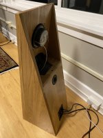
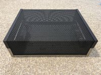
This is an "Open Baffle Reflex Hybrid" which has the upper half of the woofer exposed on the rear of the cabinet (dipole), with the lower half of the woofer reflex loaded.

+hybrid_open_back_reflex__29572.JPG

+hybrid_open_back_reflex__2953.JPG


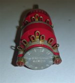
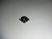
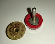
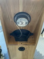
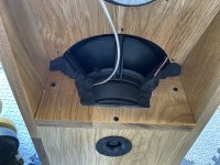
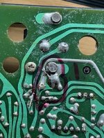
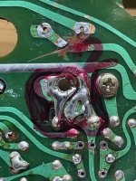
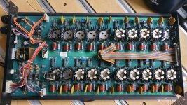
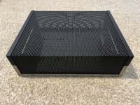
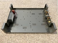
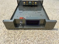
A special divider (see center photo of the oddly shaped piece of wood) wedges across the middle of the woofer, creating separation between the open baffle top and the bass reflex bottom. This structure comes to within 1cm of the cone (left picture). Right photo shows the speaker before I installed the divider. The opening just behind the cone doubles as the bass port. There is no other port.

+hybrid_open_back_reflex__2946.JPG
+hybrid_open_back_reflex__2943.JPG
+hybrid_open_back_reflex__2944.JPG

The closer I was able to get the divider to the woofer cone, the lower I could tune the port. A larger gap would tune the system to a higher frequency. A smaller gap would tune lower, but invite the cone slapping against the divider.

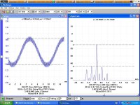
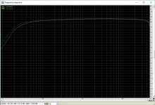
Below is the frequency & phase response in-room of the finished system:

+hybrid reflex dipole 1july2021 freq response phase.png


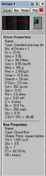
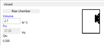
This divider is air-sealed against the magnet and spokes of the frame with modeling clay. The tuning frequency is 57Hz which was the lowest I could attain, given the size of the enclosure (~1ft^3 / 28 liters) while not making the space between the divider and the woofer cone prohibitively narrow.

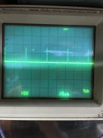
The impedance curve shows the reflex tuning:

+nadler-hybrid-dipole-RS270p-impedance.png


About 1/3 of the back of the woofer is exposed and 2/3 funnels down into the enclosure. The polar pattern is really more like a cardioid. (However, I'm sorry I only have 180 degree polar plots, not 360.)

+hybrid_polar_spectrum_70-20K.png

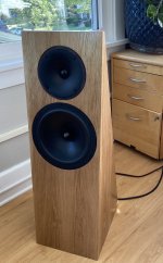
The polar spectrum shows a very even constant directivity of about 90 degrees from 100Hz to 20KHz. The tweeter is the classic Audax TW034X0 ("D34") mated to a 6.5" Troels Graveson waveguide, which makes a superb combination.

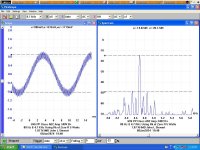
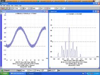
This is frequency response about 2 feet in front of the speaker. This position doesn't pick up the rear port radiation which is why you see the response droop below 150Hz. The farfield is better as you can see in a different curve above. This shows 1/3 octave plots at 0, 15, 30, 45, 60, 75, and 90 degrees. As you can see it achieves constant directivity from the bass midrange to the treble.

+hybrid 0 15 30 45 60 75 90 degrees.png


Below 100Hz the speaker becomes roughly omnidirectional with the majority of the output coming from the port. The port has a pretty decent bass peak at about 65Hz with useful output down to just below 50Hz. One drawback is that at high levels there's a fair amount of port chuffing. It's unavoidable given the narrowness of the port necessary to tune the box down to 55Hz.

A problem with this design for high excursions is that as the woofer moves, it is also changing the tuning frequency at the same rate as the signal is varying; so that creates some cringy distortion at high levels. Also it's likely I am getting cone rocking at high levels because of the asymmetry of the air loading. But it's less distortion than the same woofer in a dipole at the same volume level :^>

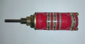
The Dayton RS270P is an excellent driver. It’s used in some pretty expensive commercial designs. It’s good looking, has very smooth response, has a hard pressed paper cone which makes a very incisive crisp character.

+hybrid open back reflex MiniDSP EQ.png

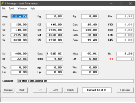
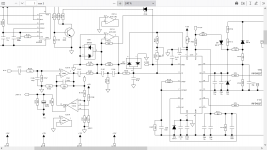
I used DSP to straighten out the anomalies, of which there are several. ABOVE, see graphic of the DSP bass EQ correction curve, labeled according to which problem is being fixed. It would be pretty hard but not necessarily impossible to execute these with a passive crossover. It would take a lot of trial and error. Not pictured is 3rd order 1500Hz xover between woofer and tweeter. The MiniDSP introduces a sharp high-pass filter below 50Hz which protects the woofer from too much excursion. Very important.

I used FIR DSP all pass filters to correct the phase response so the system is linear phase from 100Hz to 20KHz with outstanding impulse and step response.

+hybrid open back reflex impulse step.png


I could perhaps have patented this unusual enclosure design. But I don’t care to be in the speaker business, and as a business consultant I think most patents are overrated anyway. So I’m giving the design away here.

They are biamped. You can download MiniDSP file here.

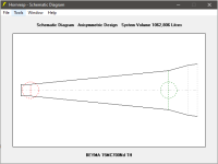
This is the cabinet sketch I gave to my Chicago-based carpenter, Seth Cothron, @studio38designs.

+hybrid_white_oak_speaker_plans.jpeg

They sound fantastic. The stereo image is wide and full; they have more bass than a 10” in a straight dipole would produce, and they produce the warm ambient sound you expect from an Open Baffle design. You can't push them terribly hard in the bass (more of a jazz speaker than a rock speaker) but they certainly play a lot louder than if they were normal dipoles; they can play roughly as loud as if this same 10” woofer was in a sealed box.

The imaging is superb everywhere in the room, even standing right next to one speaker; and they are very transparent with great clarity.

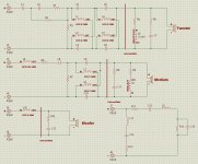
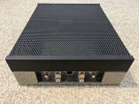
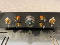
On the back panel is also a Peerless 1" dome tweeter BC25SC06-04 for back fill - I find dipoles sound much better with full spectrum on both sides.

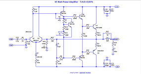
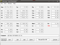
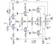
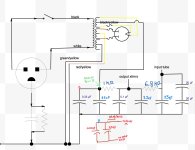
Below is the tweeter schematic. The tweeters are wired in series and the LC circuit reduces the sensitivity of the rear tweeter while making the front and rear tweeter curves match better. Woofers are wired straight to the LF amp.

hybrid_nadler_tweeter_schematic.jpeg

I built these two years ago, and a friend suggested that maybe it would be easier to just build a dipole with two separate woofers, instead of creating all of the baffling necessary to divide the output of one. So I did, and the result was the Flanagangsters which I posted about 2 months ago.

I really enjoyed trying something unconventional and I encourage y’all to generate variations of this new enclosure type.

Perry Marshall
nadler_hybrid_desmoines.jpg

Attachments

  • +hybrid_open_back_reflex__2944.JPG
    +hybrid_open_back_reflex__2944.JPG
    566.5 KB · Views: 377
  • +hybrid_open_back_reflex__2945.JPG
    +hybrid_open_back_reflex__2945.JPG
    482.3 KB · Views: 340
  • +hybrid_open_back_reflex__2946.JPG
    +hybrid_open_back_reflex__2946.JPG
    495.7 KB · Views: 312
  • +hybrid_open_back_reflex__2953.JPG
    +hybrid_open_back_reflex__2953.JPG
    461.2 KB · Views: 873
  • +hybrid_open_back_reflex__29572.JPG
    +hybrid_open_back_reflex__29572.JPG
    376.2 KB · Views: 586
  • +hybrid_open_back_reflex__2945.JPG
    +hybrid_open_back_reflex__2945.JPG
    482.3 KB · Views: 356

6N13S/6AS7G PP Amplifier schematic

Hello everyone!

I am on my 2nd Tube amplifier project (but I have quite good SS background), and I have some 6N13S tubes which I am looking forward to use as my power output tubes.
I came across this schematic which was published in Elektor 2007 but I would rather ask for some opinions about it before I start designing the PCB.
To be honest, what seems weird to me is the connection of the grid resistors of the second stage, which in my opinion should be connected to GND.
As I said, I am learning a lot so I might be wrong. Hopefully someone will explain what's happening there. I am also keen to upgrade the existing schematic eg. CCS for V1,V2 cathodes, etc.


Kind regards.

Attachments

  • Elektor June2007.jpg
    Elektor June2007.jpg
    102.8 KB · Views: 1,310

  • Locked
Peachtree new GaN-1 all "Digital Amplifier" the future?? (and it's not Class-D)

Thought this new amp from Peachtree Audio deserved it's own thread. Enjoy!!

This Peachtree could be something, it uses the far faster newest "GaN Technology" (Gallium Nitride) output devices, not Mosfets like Class-D uses.
1: has no dac in it per se, just has a (programable?) DSP processor chip to convert PCM to PWM at the end just before the GaN power output stage.
2: is zero feedback
3: no preamp is used
4: and has no buffers
5: has impressive low .004% THD, very good for an amp without any feedback!!!,
6: It just takes in the digital output from your digital source/s (it has no analog inputs).

Addicted to Audio has the older Peachtree line but not this new GaN-1 "digital-amp" yet.
Busisoft the Au importer said they'll be in soon, but yet to have an RRP put on them.

This is Peachtree Audio, and the new GaN Technology with this digital-amp, that is direct digital input from your source/s.
https://www.peachtreeaudio.com/products/gan1

Here's JD ex-Aussie, (gone back to his Pommy roots,) John Darko's very descriptive high praise review on it.
Login to view embedded media
Cheers George

Interstage coupling cap replace or bypass?

So... here is the thing. I bought this Reisong A10 a few weeks ago and out of the box it was sounding terrible. At least matched with my Castle Conway speakers. So I started digging, reading and watching videos on how to mod it. I got to make some mods and tube rolling that enhanced the sound but... I'm still missing things. Rock and other "non-vocal/jazz/classical" tracks sound muddy. I need to add that I've no idea what I'm doing, I just follow the modding videos I find 😅. It was on one of them that I heard about bypassing the orange coupling cap (0.22uf) that came from factory with a copper foil cap (0.1uf).

Now, here is the "big question". I'm ready to spend some bucks on this bypass cap, but these questions came to me:

1. Sonically speaking, is it better to just replace the cap or bypassing (parallel) it with a lower capacitance would get more improvement?
2. If the case is the second, the capacitance of the bypassing cap affects the sound? Meaning, would it have more impact (improvement) if the bypass cap had 0.1uf than a 0.01uf? I ask this because I'm looking at some Duelunds that are quite expensive depending on capacitance.

That's it. All said (or asked). Please be kind to me, it's my first post.

Does Allen Wright's Cathode Bias Resister Scheme for IMD Reduction Work? Yes? No? Maybe!! Episode ll

In this exciting episode the possibility of Intermodulation Distortion Reduction in a Class AB2 amplifier by the Allen Wright method is tested.
The amp output is PP 6V6s driven by a 6BQ7 as cathode followers direct into the 6V6 grids, Refer to the schematic,

The driving signal in 80 Hz mixed with 4.7 KHz at 12 db lower level, The measurements follow the SMPTE method.
In test A the 6V6 cathodes are taken straight to the commons rail with the exception of small resisters to allow current measurements.
At 5 watts the IMD measured 1.87 %.
In test B a 47R resister was inserted into the 6V6 cathodes lead to common. The IMD increased to 4,67 %.
In test C the common resister to the common rail was 23R, And the IMD was 3,48 &.

The Allen Wright method did not improve the IMD in this amplifier. 🙂

Attachments

  • Power Supply 6V6 PP Twin Coupled Amp.jpg
    Power Supply 6V6 PP Twin Coupled Amp.jpg
    313.3 KB · Views: 145
  • 6V6 PP Class AB2 Amp Test A.JPG
    6V6 PP Class AB2 Amp Test A.JPG
    122.8 KB · Views: 140
  • 6V6 PP Class AB2 Amp Test B.JPG
    6V6 PP Class AB2 Amp Test B.JPG
    121.7 KB · Views: 102
  • 6V6 PP Class AB2 Amp Test C.JPG
    6V6 PP Class AB2 Amp Test C.JPG
    120.8 KB · Views: 138

Broskie Tetra "All in One" Line Stage / Headphone Amp PCB (Blank)

This is a blank PCB for 9 pin Aikido line stage PCB that has a built in power supply. Can be configured as a headphone amp too.
Broskie's PCBs are first rate.

These are no longer available.

Comes with manual. Priced 25% below cost.

$49 + nominal shipping.

Attachments

  • Aikido All in One.jpeg
    Aikido All in One.jpeg
    542.8 KB · Views: 112
  • Aikido PCB.jpg
    Aikido PCB.jpg
    628.5 KB · Views: 105

Woofer suggestion for car audio

Hi everyone,
I was looking for some woofers that I could use for a car audio system. At the beginning I wanted to use four Peerless SDS P-830657 6.5 inch woofers, but then I found the Tang Band W4-1052SD 4 inch woofers. The plan is to cross them over with tweeters anyways. Do you recommend the bigger sds ones or the tang band speakers, considering they're higher in price (and probably quality) as well?
I forgot to mention that I will have a subwoofer for lower frequencies

Prospective 2-Way Setup

Hi All!

After some good advice and areas to look further into after my first post on the forum, I think I've selected a pair of drivers for my 2.0 build and hope that others might be able to take a look and let me know if I've overlooked anything or might be leaving performance or money on the table.

I plan to use Peerless D27TG35-06 Tweeter and Peerless 835025 6-1/2" Aluminum Cone HDS Woofer with a passive crossover that I will build around 2.5kHz.

I've calculated a vented box volume of 0.553 ft^3 with a 2" D, 4" L flanged down-firing port. I selected down-firing based on the location the speakers will need to be placed in; roughly 3' from listening position with 1.5' of space from the wall for one and window for the other on the side, and 2' from the back for another wall and window. Overall room size is about 10'x8'x11' which I will be treating after getting the setup together.

I'm currently in the process of building the Leach Amp to power this setup.

Looking forward to any feedback!

Dynaudio crossover questions

Hi,
I want to improve some components of my crossover and I would need information. I attach the diagram to better understand. The crossover is in two parts.
The first part of each lane is at the bottom of the enclosure (to the left of the dotted vertical line)
The second part (to the right of the dotted vertical line) is located at the top of the enclosure near each driver and is connected by a cable with the bottom part.
Is there an any advantage to separating and placing only this part of the crossover close to the driver?
Also, in the diagram at the bottom right, is a circuit connected in parallel with the input terminals. What is the purpose of this circuit?
I want to separate the mid-tweeter and the woofer to be able to go in bi-amplification, do I need to make a copy of this circuit
to have one for the mid-tweeter part and the original for the woofer? or is this circuit is usefull for the woofer or mid-tweeter only?

Thanks

Attachments

  • Schematic Crossover.JPG
    Schematic Crossover.JPG
    226 KB · Views: 479

For Sale VFET amp from first lottery

I am passing this along to the next enthusiast interested in listening to this amp from creator extraordinaire Nelson Pass - the original vfet lottery. The amp is perfect no blemishes and has maybe 50h on it and comes with the meanwell SMPS. I am very experienced builder so no bad solders burned components etc. The kit was 500usd and l would like to get it back. Buyer pays shipping. Will be packed to withstand UPS handlers.

image.jpg
  • Like
Reactions: OtisCampbell

G10 guitar amp hiss

Hi all

I’m quite new to electronics so be gentle.

I know enough to reasonably diagnose a guitar amp problem but as this is my first time with actual soldering iron in hand trying to fix things I would like to run my theories past experts first.

The amp
It’s a G10 Marshal (no reverb, twin gain pots, high middle low equaliser pots and master volume)

The problem
The gain controls produce really bad hiss even at low settings.

My thoughts on fixes
Visual inspection of the board I find no visible problems (cap leaking, dry joints or burns on components)

So do I suspect coupling caps are leaking DC - it’s my go to pat idea for hiss

Tools available
I have basic multimeter + DSO TC3 meter
To attack the problem.
I’m very competent at soldering

I’ve got a schematic of the circuit (very grainy print) but useable.

So how to trace this problem so gratefully for any help.

TIA
BTW - it’s 20+ years old

Ear 834 clone Parts

First of all, thank you for your interest.
Due to lack of time and too many projects, I offer an Ear 834 clone diy kit from Douk Audio with Mouser components, transformer choke, Mundorf caps. I have a list where the existing parts are listed.
the entire package cost me €300.
I'm offering it for €250.
Ask for shipping costs.
If you are interested please let me know.
kind regards abc4230

Heat sinking for TDA1541A?

Well, after making a rash purchase from eBay (should have bought a guaranteed good one from Bensen when I had the chance) and hoping that it’s a non-fake working chip I now realise I have no clue how to use it. I will need to put it on a board and make connections to it.

My question - I don’t see many people adding any heat-sinking. Do these chips get hot? Would cooling increase the life expectancy? Is there any point to trying to cool the package or does the heat get out via all those pins? If the heat has to be removed from the pins does that imply some design constraints? Is there even a case to be made for Peltier cooling for better performance?

Attachments

  • IMG_7367.jpg
    IMG_7367.jpg
    610.3 KB · Views: 123
  • Like
Reactions: Alexandre

NAD 3130 PCB Track layout

I purchased a NAD 3130 on Facebook Marketplace with one channel dead, the other is working. On removing the two To3 Transistors (2N3055 & MJ2955) I noticed that the track on the PCB from the transistor fixing bolt hole was bridged with solder to the adjacent track, as I have marked in red in the attached photo 1 & 2. In photo 1 you can see the solder bridge between the fixing bolt and the adjacent track and in 2 you can see I have removed the bridge. This amp has been repaired before, is this a modification I'm not aware of or just a poor previous repair?

I have the service manual and from what I can see the short in the photos should not be there on either transistor?

Any help or advice would be welcomed..

Attachments

  • IMG_NAD 1.jpg
    IMG_NAD 1.jpg
    138.5 KB · Views: 147
  • IMG_NAD 2.jpg
    IMG_NAD 2.jpg
    123.4 KB · Views: 139

xrk971 Pocket Class A Headamp GB

Edit May 28, 2020: Revised Schematic and BOM for 2SK209GR JFET and ZXMN10A08GTA MOSFETs here: xrk971 Pocket Class A Headamp GB

Edit (July 24, 2017): schematic with DC setpoints for actual standard build amp using suggested values in recent BOM. Note that adjusting R4 (as high as 51R for higher bias) gives room for tuning desired bias current vs battery life. Voltages here are useful as reference for debugging a circuit that is not working:
616921d1495124663-xrk971-pocket-class-headamp-gb-pocket-class-schematic-v8-voltages.png


Edit (June 2, 2017): A review of this amp on Headfonics.com

591117d1483961316-mosfet-source-follower-headamp-pocket-bf862-zvn4306-ha-smt-tin-case-dtr880.jpg


This project started over in this thread:

BF862 based SE Class A Headamp without the HEAT

but I thought it would be good for it to have a dedicated GB thread here. It's a superb sounding single ended (SE) Class A topology that has a predominantly a second harmonic distortion profile with just a tad bit third harmonic and not much else. The noise floor is about -125dB and dynamic range is about 96dB with THD measured to be about 0.029% at 1kHz and driving a 270ohm load at 700mV RMS. Note that most of that HD is H2 so the sound is very much like a nicest SE tube amps. Frequency response with a 47uF output coupling cap was measured at -1.5dB at 20Hz and 45kHz (probably limit of measurement as ADC sampling was 96kHz). The sims show that it can go beyond several MHz on the high end. Best part is that it fits in an Altoids tin and looks like a CMOY headamp - but it's no op amp. It relies on just two FETs. The ever popular BF862 JFET for the input and a ZVN4306 MOSFET for the output stage. The bias runs between 50mA and 60mA which allows it to last about 4 to 5 hours on a pair of 600mAhr Li-ion rechargeable 9v batteries. The amp dissipates about 2w so never gets hot but makes a nice hand warmer for your pocket in the winter.

This is the basic circuit - very simple and it's what gives it a natural and very musical sound that is engaging, lively, never sterile.

591187d1483977924-bf862-based-se-class-headamp-without-heat-pocket-class-bf862-zvn5306-ha-v1.png


Here is the predicted HD profile:
591189d1483977924-bf862-based-se-class-headamp-without-heat-pocket-class-bf862-zvn5306-ha-v1-fft-1khz.png


Here is what the hand made prototype looks like:
591358d1484063759-bf862-based-se-class-headamp-without-heat-pocket-class-bf862-zvn5306-ha-v1-new-oscons.jpg


You can listen to this amp as recorded with UCA202 connected to a 270ohm load resistor. Change the file name extension from .asc to .mp3 to listen.

http://www.diyaudio.com/forums/atta...wo-transistors-clapping-pocket-class-clip.asc


This is the layout for the actual board being sold for this GB:
594826d1485450543-bf862-based-se-class-headamp-without-heat-pocket-class-gb-layout.png


This is the associated schematic that goes with this layout:
595303d1485672195-xrk971-pocket-class-headamp-gb-pocket-class-schematic.png


Many thanks to BabyDontHertzMe (BDHM) for making the layout and to Agdr for providing the initial Altoids footprint Eagle file.

Here is the measured HD using Focusrite Solo 2nd gen at 96kHz and 24bit:

595010d1485521883-xrk971-pocket-class-headamp-gb-img_6145.png


The HD measured using a UCA202 at 16bits and 48kHz looks like this:

591989d1484374923-mosfet-source-follower-headamp-bf862-vzn4306-fft-via-rca.png


Edit Feb. 18, 2017 - Here is the latest measured frequency response and THD from the GB PCB:
s-l1600.jpg


Edit Feb. 18, 2017 - Here is the latest measured FFT from the GB PCB measured for 1kHz excitation at 700mV into a 270ohm load:
s-l1600.jpg


This headamp can drive headphones with impedances as low as 30ohms no problem. The GB has already started in the other thread and is currently at 6 people and 11 boards. We have enough critical mass but I want to keep it open a bit longer to make sure everyone who wants one gets to place an order.

Please send me PM for pricing of bare PCB's or matched FETs.

Pre-made amps and pre-soldered SMT-only boards and full kits available here:

XRKAudio designs for superb natural sound. by XRKAudio on Etsy

Please use the quote feature to add your name and desired number of boards to grow the list:

Pocket Class A GB Order List:

(As of 02:00 EST, Jan 29, 2017)
xrk971 - 2 boards
pcgab - 2 boards
zman01 - 2 boards
stellarelephant - 2 boards
samoloko - 1 pcb
lui04 - 2 boards
Morde - 2 board
cyteen - 2 boards
funch - 2 boards
syyma - 2 boards
av-trouvaille - 2 boards
Mituisho - 2 boards
bogde - 2 boards
faltinsen - 2 boards
vanofmonks - 1 board
M_Balou - 2 boards
dwpeterson - 1 board
agdr - 1 board

(add your name and number of boards here. Please use quote feature to grow list.)
Report Post

Latest BOM is post 15:

xrk971 Pocket Class A Headamp GB - Page 2 - diyAudio

BOM errata for C9 and C11:

http://www.diyaudio.com/forums/group-buys/302859-xrk971-pocket-class-headamp-gb-4.html#post4971339

Edit - Jan 9, 2017: The GB PCB works! Sounds fantastic.

598242d1486680129-xrk971-pocket-class-headamp-gb-pocket-class-headamp-test-04.jpg


598239d1486680129-xrk971-pocket-class-headamp-gb-pocket-class-headamp-test-01.jpg


Final as-built schematic:

596768d1486181745-xrk971-pocket-class-headamp-gb-xrk971-pocket-class-headamp-schematic-v8.png


Final as-built BOM:

All resistors 0805 package, metal thick film, 1% on specified parts, else 5%. Yageo 1% 0805 SMT from Digikey are $0.77 for 100
R1 100k (5%)
R2 47k (1%)
R3 1k (1%)
R4 33R (1%) ** try experimenting with 39R and 47R to give higher bias current but more H3 and less H2 but overall lower THD **
R5 270R (1%)
R6 47R (5%)
R7_1 470R (1%)
R7_2 470R (1%)
R7_3 470R (1%)
R7_4 470R (1%)
RL 270R (5%) User select (optional, use for higher current draw on amp)
RLED 15k (5%) Current limit for LED, 15k or value according to supply voltage

C1 Input cap 5mm pitch up to 5.5mm wide (Wima 2.2uF MKS2B042201F00JSSD)
C2_1 Output cap 3.5mm pitch, 8 dia (390uF 20v Panasonic OSCON 20SEPF390M) or Nichicon AK 470uF if you can fit it Edit: I highly recommend a 1000uF 16v OSCON here for low impedance phones.
C2_2 Output cap 5mm pitch, up to 9mm wide (Wima 1uF MKS2C041001F00KSSD) Edit: I highly recommend a second 1000uF 16v OSCON here, if you have 30ohm or lower phones, and place Wima on SMT side.
C3 Rail cap 100uF 3.5mm pitch, diameter whatever you can fit in the tin (100uF 20v Panasonic OSCON 20SEP100MX) - or Nichicon 2200uF 16v lay on its side
C4 Rail cap 100nF 1206 package (50v X7R)
C5 Additional 100nF rail cap 1206 package (50v X7R)

Q1 BF862 (771-BF862-T/R)
M1 ZVN4306GTA * a great alternative is ZXMN10A08GTA now that 4306 seems to be out of stock or EOL? **

Switchcraft 3.5mm stereo jacks x2 (35RAPC4BV4)
Alps 10kOhm stereo pot with power switch (RK0971221Z05)
3mm round LED (red or green)
4-pin 2.54mm pitch power connector (see post #44)

Edit (Dec 22, 2017) - here is the latest BOM that I use for low impedance cans with a smooth sound signature:

http://www.diyaudio.com/forums/group-buys/302859-xrk971-pocket-class-headamp-gb-140.html#post5284641


Here is a Digikey shopping cart for all SMT parts. Good to have assortment of R4 values ranging from 33R, 47R, 51R, 56R, 68R to tune bias current on M1. Start with 47R and increase R4 for higher bias - aim for 50mA to 55mA across R7.

Here is a ONE-STOP shopping cart for Digikey put together by Sodacose. It doesn't have the nice red Wima's but should be fine if you are not a capacitor snob 🙂

http://www.digikey.com/short/3wzbtt


598314d1486711437-xrk971-pocket-class-headamp-gb-pocket-class-headamp-test-05.jpg


Here is the template for drilling the holes in the mint tin, courtesy of Agdr (same pattern as his Super CMOY 1688 as the pot, LED, and 3.5mm jack locations are the same).

https://www.diyaudio.com/community/threads/xrk971-pocket-class-a-headamp-gb.302859/post-4985588

Desktop version with IRF10's and 115mA bias here:
http://www.diyaudio.com/forums/group-buys/302859-xrk971-pocket-class-headamp-gb-38.html#post5014544

604414d1489131602-bf862-based-se-class-headamp-without-heat-xrk971-desktop-class-headamp-irf610-v2.1-build-02.jpg


Edit (July 28, 2017): DSP Convolution Files for OB-1 and DT880-250 headphone!
Here is a neat thing to try if you want to hear what your headphone would sound like if it followed the ideal Harman target response. Byrtt posted some directions on how to do this in DSP and kindly provided convolution files for DSP processing of the OB-1 and DT-880 headphones (I happen to own both 😀). Sounds very very nice - definitely worth a try.

http://www.diyaudio.com/forums/group-buys/302859-xrk971-pocket-class-headamp-gb-100.html#post5134580

Edit Aug 28, 2017: a very nice USB LiPo charger and load balanced with cap multiplier mod by RaptorLightning.

http://www.diyaudio.com/forums/group-buys/302859-xrk971-pocket-class-headamp-gb-118.html#post5168688

muypU8W.jpg


Edit May 9, 2018: Schematic and BOM for the Desktop Class A Headphone Amp:
http://www.diyaudio.com/forums/group-buys/302859-xrk971-pocket-class-headamp-gb-173.html#post5428007

PCB layout courtesy BDHM and JPS64:
679262d1525754963-xrk971-pocket-class-headamp-gb-desktop-amp-pcb-photo-jpg


679489d1525836497-xrk971-pocket-class-headamp-gb-xrk971-desktop-amp-schematic-v2-production-portrait-png


Stuffing guide:
679340d1525781867-xrk971-pocket-class-headamp-gb-20ea62a1-e088-4df5-b970-41c61c49d779-jpg


679339d1525781867-xrk971-pocket-class-headamp-gb-0bc0cbc4-0d1b-41b9-9c0c-04ed6985b5a3-jpeg


Update Jan 8 2019: New ZXMN10A08GTA to replace ZVN4306GTA provides higher transconductance for lower output impedance and higher damping factor. xrk971 Pocket Class A Headamp GB

Update Mar 6, 2020: New Resistors for 2SK209BL and ZXMN10A08
822912d1583527730-xrk971-pocket-class-headamp-gb-pca-2sk209bl-zxmn10gta-v3-jpg

Attachments

  • IMG_6144.PNG
    IMG_6144.PNG
    45.3 KB · Views: 1,591
  • IMG_6145.PNG
    IMG_6145.PNG
    72.3 KB · Views: 14,287
  • Like
Reactions: Kdent

Hum&Buzz problems DIY CE pre-amp

Hi everybody,

I am a musician and I want to start building some pedal effects, pre-amplifier, filters and so on. Just for hobby 🙂
My target is to learn starting from descrete components (I think it is the most basic level, isn't it?), so my first project is to build a simple pre-amp using a transistor in a CE set-up.

I was experiecing some buzz/hum problems with my CE amp. Since I want to learn, I attach a detail report and two recordered audio instead of write here.
At the end of the report there are my questions 🙂

I hope this is the right way to explain to the comunity my troubles and I hope this will be helpful to somebody.

Thank you

Andrea

Attachments

BUZ210 MOSFET Replacement

Hi all,

I have several power amplifiers that are used to run a vibratory shaker table that I own and some of the BUZ210 N-Ch MOSFETs are testing bad. There are nine of the amplifier modules in the controller cabinet with 20 BUZ210s on each module for a total of 180 FETs. I'm looking for a replacement MOSFET to the BUZ210 and have nearly given up on finding one in a TO-3 package. I'm considering spinning a custom PCB to adapt a surface mount MOSFET to the TO-3 mounting holes and heat sink, but I do not know how close I need to match parameters like input capacitance, transconductance, charge, etc.

The specs for the BUZ210 are attached. I'm considering something like the IRFAC50 (TO-3) package, or something like the AOD380A60C. The BUZ210 has an input capacitance of 3800 pF @ 25 Vds. The parts I'm finding that meet Vgs and Id specifications have much lower input capacitance (e.g. 900 pF @ 100 Vds).

How close do I need to match these other parameters for a power amplifier like this? The amplifier energizes a very large field coil to create a field that moves the shaker table up and down. I also attached a picture of one of the nine amplifier modules. Some of the BUZ210s are removed for testing.

Thanks!

Attachments

Add LC Filter / Choke

The existing power supply in my audio amplifier lets quite a bit of ripple through producing audible hum. I am planning to add an LC filter to the existing power supply to help filter more of the ripple. I have included a schematic of the power supply with notes showing what I plan to do. After running a simulation in PSUD2 this should greatly reduce the ripple on the B+. The issue is that there is not room left in the amp chassis for this new LC filter. I am planning to mount the new LC filter in its’ own chassis and connect it to the existing power supply using this cable, making it as short as possible. The cable will be for points A, B, and GND shown in the schematic.

Does anyone see an issue with this?

Thank You for your help

Attachments

  • Screenshot 2024-02-08 at 8.05.27 AM.jpeg
    Screenshot 2024-02-08 at 8.05.27 AM.jpeg
    179.3 KB · Views: 323

How to

Hi i recently bought a Fnirsi 1014D oscilloscope which has an inbuilt function generator. But the amplitude of the signal is fixed at Peak to peak 2.5V. I tried connecting a volume pot on the out to reduce the amplitude but the signals came out distorted, Is there any way to make it variable by adding an external circuit?

https://www.elektor.com/blogs/review/fnirsi-1014d-digital-storage-oscilloscope-review

New Audio Op Amp - OPA1622

We released a new audio op amp this week specifically targeting ultra high fidelity headphone amplifier applications: http://www.ti.com/product/OPA1622

Some of the highlights:
  • 80mArms linear output current (+145/-130 mA short circuit)
  • Extremely low distortion into low impedance headphones: FFT on the front page of datasheet shows -133.6dB 2nd Harmonic at 50mW into 32 ohms
  • Ground-referenced enable pin compatible with 1.8V logic and click/pop suppression. 5uA of supply current in shutdown mode.
  • 2.8nV/rtHz input voltage noise
  • 0.8pA/rtHz input current noise
  • 2.6mA supply current when enabled
  • 136dB open loop gain with 600 ohm loads
  • Stability with >1nF cap loads in a G = -1 configuration, no isolation resistor
  • Very good PSRR: 97/123 dB at 20kHz.

I know the package really isn't hobbyist friendly (3mm x 3mm SON-10) but I thought it would still be an interesting product to many on here.

DIY tape deck, preamp...

Hello,
Due to the fact that you can't buy new, at least half decent tape deck today and that my AKAI CS-F21 is having more and more problems do to it's age, I decided to build a tape deck mainly from old parts that I have laying around.

Tape deck from 2000 BMW 5 series radio made by Becker... soft buttons, plays A & B sides one way, motorised tape loading, photoresistor sensor on both reels...
I didn't do any measurements, but the sound is really nice, even with old beat-up tapes...
I solved the logic with Arduino and it does the job good... I still need to add A-B side logic and photoresistors logic...


For the preamp I will copy design from another BMW unit... 2000 BMW 7series navigation unit made by Phillips (basicly tape player, keypad and display in a package, amplifier and the main logic is seperate unit (in the trunk).

I will copy the design and build my own, because it just sounds so good, has Dolby NR B-C, norm and metal tape option, side A-B play, mute detection...

For now I"m testing with the original board, bricked to turn on without main unit (the one from the trunk).

Audio signal goes to the BA3430FS tape preamp, then to the HA12161FP Dolby IC and then to the TDA7053AT.

According to the datasheet TDA7053AT is an Dc volume controlled amplifier and I am wondering if I need it because I get good signal from DOLBY IC.

Can I take the signal from DOLBY IC? The new DIY unit will not have it's own amplifier, just line output at the back -possible short circuit scenario...


I was thinking about why Phillips added TDA at the end of signal chain and my assumptions are:

-Short protection
-Dc volume control
-Impedance matching (I don't have the main unit, so I can't confirm)
-Because the main unit was so far away in the trunk:
-amplification
-solution to ground loop noise problems as TDAs output is floating 5v above the power gnd


What do you think? Would you keep the TDA?

Thank you for help

Attachments

  • 20240229_091144.jpg
    20240229_091144.jpg
    507.7 KB · Views: 104

Arcam CD72 DAC mod

Hi. I was thinking about improving the DAC in the Arcam CD72 player. Currently there is PCM1716 dac. I would like to put WM8740SEDS dac chip instead. Pin by pin they seems to be the same. Could someone advise me if it is enough to "resolder" the chips or I need to do something else?

Attachments

  • page-000001.png
    page-000001.png
    47.6 KB · Views: 61
  • F02FC91593C58ACC2650F11D4132345E-1.jpg
    F02FC91593C58ACC2650F11D4132345E-1.jpg
    315.9 KB · Views: 69

DIY 3-way SH-50 Synergy Horn Clone: Tuning Phase? Pics and vid Included

Hello and thanks for tuning in to this thread. This is my first speaker build and post on the forum, so please excuse my ignorance of some of the finer points of speaker design.

This prototype build is a tri-amp clone of the Danley Sh-50 with active DSP processing. My goal is to get 60hz to 16khz with a pretty flat response and operate around 130dBc @ 1m.

So far everything is working great at the desired volumes but I would like to improve the phase of the speaker and maybe get some feedback on ways I can improve this build before I commit to building the final pair in 3/4 Birch. Any comments are appreciated!

***
Attached is a picture of the SPL/ Phase response in REW, measured at the center of the horn opening with calibrated levels and RTA mic.

XO: CD (HP -48 Linkw @1350hz), MIds (-12db Butter Low Pass @ 1350hz and HP -12 DB Butter @ 350hz), Sub (HP -48 Linkw @ 60hz and LP -48 Linkw @350hz)

EQ: Peak EQ boost at each XO q=1 +8db

Build parts list:
3/4 MDF
Ashly Protea SP 4.8 DSP
PRV 290PYS
4x Pyle 5" Sealed Mids
2x Faital 12FH510
Amps:
EV CP1200 - CD
EV CP2200 - Mids
EV CP3000 - Sub


IMAGE 2022-03-08 15:26:47.jpg
IMAGE 2022-03-08 15:28:13.jpg
Screen Shot 2022-03-08 at 3.19.24 PM.png

Login to view embedded media

Receiving I2S audio on STM32 using DMA

Hello everyone!
I am currently designing a simple pass-through application for I2S audio on the STM32F072RB microcontroller. Basically it receives data on one of its I2S peripherals and forwards them to the other I2S unchanged. This is done using double buffering and a DMA is utilized on both RX and TX sides. Both I2S are in slave mode on the same clock domain. The source of the audio signal (I2S master) is the Up2Stream Mini bluetooth module from Arylic. The power end is the TAS3251 chip which takes the I2S data coming from the STM32 directly. Later I would like to enhance this application with some low/high pass filters, volume control and FFT.

But what is the problem: sometimes just after the powerup/reset the receiving I2S is somehow unable to lock on the incoming clock and that results in the entire transmission being corrupted (noise or silence coming out of the STM32 - see the video where I repeatedly reset the MCU and few occasions show the corrupted audio). I have quite isolated this problem and I am 90% sure it is caused by the receiving I2S. But what I don't know is the root cause and if it is the wrong locking on the clock, how to recover from this?
Both the receiving and transmitting DMA runs in circular mode, so there is actrually very little code to implement this whole thing - just an init and one ISR to swap the dual-buffer.
I am also attaching screenshot of the receiving I2S config.

By any chance, is there someone who has an experience with I2S audio on STM32 and can give some hints on resolving this?

Thanks and Happy New Year to everyone!

Attachments

  • IMG_0678.mp4
    14 MB
  • i2s_settings.png
    i2s_settings.png
    9.9 KB · Views: 509

Cyrus 1 output transistor question. push-pull?

Hi all

I fixed my brother's mission cyrus two for him recently (pre amp power supply circuit track fault and a sulphided selector switch. He now thinks I'll be able to fix his daughter's cyrus one.

that's a bit sicker though.

when i plugged it in one of these white things glowed red and started smoking.

I assume this isn't good and unplugged.

So I'm guessing (wildly, cos I'm not knowledgeable) that a transistor has gone open and too much current ran through the white thing ?

<a href="https://ibb.co/mtvZVG"><img src="https://thumb.ibb.co/mtvZVG/20171209_174840.jpg" alt="20171209_174840" border="0"></a>

I thought I'd replace the white thing, and all 4 output transistors but they all have the same marking on them (C8837 CYRUS PT7) and i expected each channel to have a pnp and an npn ? Im also guessing they aren't made by mission and are obsolete.

could they be different but have the same code marked on them ?

can i test them with a multimeter or will that not work cos of failure ?

I could do with knowing what to order.

thanks for any help

Max Pentavent 1250 12 inch woofers

I have four Max Pentavent 1250 drivers for sale. These were used in an open baffle speaker project, but not used enough to be run in. They are in perfect condition.

These cost me £60 each back in 2005 and I will accept £70 for a pair or £120 if somebody takes all for. Shipping extra of course.

Incredible bass drivers designed to give
exceptional performance in a wide range
of applications.
With the precision and speed to satisfy the most
discerning listener and a robust, superbly engineered design
to handle the massive output of powerful amplifiers, these
drivers can deliver superb sound quality across a wide
bandwidth. Long excursion coils and low resonance push the
bass frequency performance of these drivers well past what
has long been considered ‘the standard’ to a depth most
drivers only dream of, making them ideal for subs, whilst
excellent midrange extension and a smooth roll-off make
these drivers ideal for any high quality 2-way or 3-way
system.
• ‘Pentivent’ 5 vent design for noise free cooling
where it is needed right into the heart of the voice
coil.
• Multilayer Kapton KSV voice-coil former for
high power and performance (K2= 2 layer, K4 = 4
layer).
• Graduated rubber surround for long lasting
performance, low resonance and excellent
damping.
• I.M. cone impregnated with carbon for excellent
rigidity and very high strength to weight ratio
minimises cone break-up and lowers distortion.
• Anti-resonant black chrome chassis with oval
windows and high quality steel to reduce basket
resonance.

PV1250 specs.jpg


maxpv1.jpg


maxpv2.jpg
woofers1.jpg

Subkick modification

I have a speaker with the below specs that I currently use as a subkick microphone (speaker wired in reverse)
I would like to add a passive low pass filter and understand that I would probably need an inductor coil, my question though being an absolute electronic newbie, what kind of coil would I need and would this cause problems to the electronics of my sound card receiving this signal?

much appreciated legends.

Specification Sheet 165mm Polypropylene Bass Driver Description 165mm (6.5") speaker • Ideal for bookshelf hi-fi speakers • Polypropylene cone • Pressed steel basket Driver Parameters Electrical / Mechanical Voice coil resistance (Revc): ................................6.6 Ω
Impedance at Fo (Zo):........................................40.8 Ω
Resonant frequency (Fo): .................................48.4 Hz
Effective piston area (Sd): ..............................0.013 m2
Force factor (BL): .............................................6.23
TM Sensitivity (SPL): .............................87.5 dB @ 1W/1m
Acoustic volume (Vas):........................................20.7 L
Mechanical Q (Qms): .............................................3.36
Electrical Q (Qes):................................................0.648
Total Q (Qts):........................................................0.543
Compliance (Cms):...................................861.36 µm/N
Total moving mass (Mms): ...................................12.5g
Diaphragm mass (Mmd):......................................11.7g
Voice coil height (Hvc):......................................7.8 mm
Air gap height (Hag): ............................................4 mm
Maximum linear excursion (Xmax):...................1.9 mm
Motor Impedance Voice coil inductance @ 1kHz (Levc1): ...........1.03 mH
Voice coil inductance @ 20kHz (Levc2): .......0.474 mH
Resistance constant (Krm): ...........................0.776 mΩ
Reactance constant (Kxm): .............................10.1 mH
Resistance at 1kHz (Res1):................................2.26 Ω
Resistance at 20kHz (Res2):............................34.86 Ω
Resistance Exponent (Erm): ..............................0.9123
Reactance Exponent (Exm): ..............................0.7394

WinISD vs. BassBox 6 Pro

I've been playing on box simulation softwares: WinISD and BassBox 6 Pro.

Driver used in the simulations is a Scan-Speak 26W/4558T00. The enclosure selected was simply a closed box with Qtc of 0.5. Nonetheless, they gave different results.

BassBox 6 Pro suggested a box volume of 1.0 cu.ft for the target Qtc (Qtc = 0.5), whereas WinISD suggested a 2.7 cu.ft box for the same Qtc.

So, which one can be trusted?

Attachments

  • BassBox 6 Pro.png
    BassBox 6 Pro.png
    8.7 KB · Views: 164
  • WinISD.png
    WinISD.png
    2 KB · Views: 154

Square Tractrix Front Horn

Hello to all members of the forum, my English is not that good,so if i make some mistake fill free to lough. Now a question. After making some speakers from open bafle ,standard BR,single driver , DML and so on, i want to do somthing new to me. I have a pair of Fostex 206E drivers, and i want to put them in a front square horn. For the low end i build two BR boxes around 80L, Horn should be from 200Hz up, and for the top i have some eminence CD in horn. Problem is, im not good in all the programs that are available ,like hornresp, its very confusing for me so i need your help. Can someone just make a calculation for me, like, mouth is 70cm by 70cm, distance from the throat is ...cm. As i read somewher two sides can be flat , and two bent. I hope i dont ask too much of you smart people. I hope that i properly explained what help i need. Thanks in advance, Dejan.

TOTL (diy) tube headphone amp?

Looking for a TOTL diy tube head amp with very nice parts that is warm and rich sounding. I guess something of the caliber of DNA Stratus / stellaris. Are there any schematics and plans for something like this? I do have a modded crack which I like but I want to go beyond.

I guess L0rdgwyn's Aegis guide is the closest but was thinking of something even beyond that. From the comparisons I read his amp didn't really get past even a V3 stratus.

This would be for dynamic driver cans.. 32 ohm and 300 ohm.

No specific budget but if you absolutely insist on a budget then under $10k (ideally under $5k)

Thanks!

Weathers turntable info

I've got a weathers turntable that I'd like to know more about It uses the Weathers Professional Stereo System pickup (PS-11) which I understand works on a capacitive principle. Which explains the "polarizing supply" in the base, which includes two modules that presumably contain amplification circuitry. I've recapped the power supply but detect no output and without a schematic I can't see how to determine whether the problem is in the stylus or in the amplifiers, and if it's the stylus I suspect I'm out of luck anyhow. From reviews I've read it will track at 3/4 gram and was considered to be a high performance system when it was in production. It would be fun to get it working again - the very lightweight turntable certainly flies in the face of conventional wisdom.

I've found the manual on vinylengine but am caught by the usual Catch 22, I can't download it because I'm not a member, and they're not accepting new memberships. It probably doesn't disclose the contents of the modules but I'd like to have a copy anyhow if someone who is a member would be good enough to download it for me.

I'm curious if anyone has experience with the PS-11 or this turntable that uses it. Thanks, Bob.

Attachments

  • Weathers PS_11.jpg
    Weathers PS_11.jpg
    64.4 KB · Views: 111

Ceramic socket problem

Various discussions about sockets, I’ve not yet seen this issue.

Tubes won’t fit. These are Audio Note, from Parts connexion (I’ve written them moments ago), pricey little beasts, silver-plating, UK craftsmanship (probably sourced outta Sri Lanka or some former colony) bought ‘em Sept 26, 2023, never thought to even TRY ‘em out until today. Curious if anyone has ever had this issue.

Locator pins on every tube from 1940’s-modern mfr (Sylvania, NU, GE, Tung-Sol, various Chicom and Russky tubes) will not go into the Audio Note too-small locator holes.
What’s worse is, tube-savers, and 6F8G/6C8G adapters don’t either. At all. Don’t even make pin contact.

I just got all the socket holes cut out this weekend, I have some other ceramic sockets but the tops are closer to 1”, not 1.125” and distance from mounting screws is too close to use.

No joy.

IMG_8656.jpegIMG_2780.jpegIMG_2781.jpegIMG_2781.jpeg

Windowing log-swept chirp signals for speaker measurements?

For a variety of reasons, including:
  1. I'm trying to learn Python
  2. I'd like to have a very compact speaker measurement script I can integrate with stepper motor controls for a diy Klippel scanner
  3. Now I'm just curious
...I'm writing a simple Python program to create, and then pass as audio output, a log-swept chirp signal, and simultaneously record the response, for measuring loudspeakers.

The scipy chirp is based on:
cos(phase + (pi/180)*phi)​
where phase is the integral (from 0 to t) of 2*pi*f(t). For a log-sweep, f(t) = f0 * (f1/f0)**(t/t1). I'd like to avoid the sharp corners at the beginning and end of this function. They may not be a huge problem in practice, but they're a bit ugly.

I looked up Room Eq Wizard's solution, and it starts the sweep an octave below the user's stated low frequency limit, and ends an octave above the user's high frequency limit (Nyquist-limited). I don't love this solution because the sharp corners are retained, and the device under test must withstand a wider bandwidth stimulus than necessary.

So I thought I might extend the chirp signal at the low and high frequency ends with a few cycles of a half-Hann-windowed cosine function, with frequency set to the low and high frequency limits, to smoothly extend the chirp signal and avoid the corners. Is there a reason this is a bad approach? Has the industry already converged on a smarter approach I'm just ignorant of?

I'm a Python newb, and audio hobbyist, so I'm confident I'm ignorant of a huge swath of material that was established ages ago. Patience with that status would be appreciated.

Few

Acoustic versus electric crossover slope - how to design properly using DSP? Please advise...

I am trying to get my speaker knowledge on a higher level. Until now, I usually implemented crossovers considering the electric slope only (plus maybe some delay). Is there any writeup on how to design the crossovers considering the acoustic slopes (e.g. the proper way)? I think I understand some of the basic principles, but I would definitely like to get some tips and tricks where to start. I can use REW and both single channel and dual channel measurements. The DSP I have now is limited to one global stereo EQ and 7 fully parametric EQs + HP and LP filters - Bessel, Butterworth, L-R and max 24 dB / oct slope.

I tried today the Harsch alignment (electric) for both MEH prototypes and it seems the transients are better than with LR24 I had before. Might be just expectation bias, I need to confirm that with measurements later. That was the motivation to get deeper into it. Any input will be appreciated.

DAC word clock really needed? Active monitors vs. multiple USB DACs

Dear Members,

I'm designing my HTPC-based 5.1.2 system, cabling done and are in the walls.
Now comes the weird part on digital side which I don't really understand:

- when I want to use multiple consumer USB DACs (e.g. Topping E30), some folks tell me their clocks need to be synchronized else I might face some audible or non-audible errors during movie or multichannel music
(A 8ch DAC would be convenient but I'm interested in the theory now).

- on the other hand, we have plenty of 2-way active speakers where each of the speakers have individual built-in (usually) classD amp+DSP combo with active filtering.
And of course their imagined block diagram begins with an analog XLR input (AD conversion) and then after the DSP, 2 DA conversions (woofer, tweeter).

The active speaker's DAC part might be on the same clock, a simple 2ch DAC for woofer/tweeter, but the boxes themselves aren't connected to eachother at all, hence their DAC parts are NOT on the same clock.

Why is it sooo important to use 1x 8ch DAC (same word clock) or multiple stereo USB DACs with synced clock (very expensive), while with 2+ active speaker boxes they have 2 separate DACs operating inside without knowing about the other and we state it works and is good ? Some clarification would be great.

So, in studio monitor usage, we seemingly don't care of the built-in DACs between the 2 monitor speakers, for them to be in sync or to run from the same master clock.
Meanwhile, when using 2 or more consumer DACs, we do care about master clock.

What's going on ?

A studio monitor 2-way stereo setup with XLR analog inputs have their built-in DACs just like having 2 USB DACs connected to the PC, one driving the left side woofer+tweeter pair and the other driving the another side.
Or is the DAC master clock's existence only important in case of woofer/tweeter sections within one box, for active amplification... but NOT important between L/R side boxes due to them representing a different signal anyway ?

  • Locked
For Sale NOS NIB GE VT-4-C 211 Triode Tube General Electric

2 Brand New in Box VT 4C 211 Tubes
Comes in original box dated August 1943
Order date 6/30/1942

$325 each + shipping and insurance is optional

Tubes are located in the US. I am willing to ship overseas
Please note shipping overseas is very expensive

1708726258639.png

Attachments

  • Attachment.jpeg
    Attachment.jpeg
    303.6 KB · Views: 85
  • Attachment.jpeg
    Attachment.jpeg
    329.6 KB · Views: 82

Dyna MKIII blowing fuse at 90volts

I've been using a DYNA MKIII that just started blowing the fuse, but not until around 90volts AC while being brought up slow with a variac. All caps are new, KT-88s are new, GZ-34 Rectifier is new, 6AN8 is new. Doesn't draw more than 0.25 amps at lower voltages, but "pops" real quick at 90VAC. All filaments heat up. It was working yesterday, but I'm stumped. Thanks for any ideas. I don't see any obvious shorts, smoke, sparks. I haven't done any voltage checks yet. That's tomorrow.

For Sale Dynaco 120 aftermarket chassis - two tone

This is a modified Dynaco 120 replacement chassis by DAL Audio. The bottom has been powder coated in gray (maybe gun metal?) and the top is the stock black. It's in good cosmetic condition with some light scratches on inside and bottom--some photos are unkind. The crappy plastic feet are gone, replaced with Hudon Hifi silicone feet (I can throw in some extras too). I am looking for offers, just send me a private message. Mind you, I will part out if you don't want some components. You are probably stuck with that Sure housing, though you could turn it into a VU meter, temp meter, etc.. I have the custom box/packing for this and it's light, so it will ship well.

On one end of unit:
DH Labs CM-R1 RCA jacks
Switchcraft B3M XLR jack - I used this for low voltage power supply
Parts Express mini speaker jacks

On the other end:
SMAKN voltmeter within a Sure ME-DV42331 housing--the Sure kept frying if it got a touch over 30V, so I replaced the guts with something that could handle 40V.
NKK S7A dpdt switch

Attachments

  • case6.JPG
    case6.JPG
    773.9 KB · Views: 89
  • case5.JPG
    case5.JPG
    670.6 KB · Views: 87
  • case4.JPG
    case4.JPG
    789.4 KB · Views: 85
  • case3.JPG
    case3.JPG
    742 KB · Views: 82
  • case2.JPG
    case2.JPG
    511.1 KB · Views: 90
  • case7.JPG
    case7.JPG
    389.7 KB · Views: 83
  • case12.JPG
    case12.JPG
    386.3 KB · Views: 84
  • case11.JPG
    case11.JPG
    442.2 KB · Views: 85
  • case10.JPG
    case10.JPG
    443.3 KB · Views: 85
  • case9.JPG
    case9.JPG
    316 KB · Views: 87
  • case8.JPG
    case8.JPG
    523.6 KB · Views: 89

Building the HyperSET

Hi,
this great preamp from @xrk971 has only a GB-thread, so I thought it would be cool to have a build thread too.
Even if I'm the only one who builds it AND publishes the progress 🤔 I hope with this thread to motivate the others who also bought the board.
This is there original opening post of the GB where X announced the amp (which is part of a great commercial amp)
https://www.diyaudio.com/community/threads/btsb-with-tube-buffer-hyperset-gb.396848/post-7292901
I have the board since many months, but I have so many projects, so it took some time to start with it.

In the first step, I temporarily wired the board on a test bed to simply test whether it worked and of course to hear the sound.
And it sounded very promising.

PSX_20240203_213348.jpg


PSX_20240204_204759.jpg


So I decided to go all-in (or very-much-in).
Chassis work began, but as it happens, more ideas came up during construction... volume with remote control... but then I need an internal 5v converter, so I have to make a pcb... input selector with RCA and XLR inputs, but then I have to make another pcb... I made my last pcb about 30 years ago... so I planned it the old fashioned way on paper, drilled holes in the board, then drew the conductor tracks with a permanent pen and finally etched them in FeCl3. Flux and cover with solder, done. It's a lot of fun and can be completed quickly.

PSX_20240211_144348.jpg


PSX_20240214_201635.jpg


As you can see, the chassis is a combination of parts from @Gianluca and they will be combined with custom made front and rear panels.
And here the current status from today: SMPS, 5vdc converter, input selector, remote control and amp board working great.

PSX_20240217_162120.jpg


Next step will be completing the chassis, and wiring everything together. I enjoy this project very much 😀

Subwoofer Build advice

Hi all,

Looking to build some subs for my new house. Was originally looking at a full marty with Dayton Um18-22 for home theater duties.
It would have to go in one corner of the room due to its size. I only have a front wall i can put subs on, no wiring or space on side walls or behind.
I realise one sub is not ideal, so i'm happy to make a couple. I have a couple of 15" drivers i bought for a speaker build i never went ahead with - FA-15PR400.
Could I build the full marty and put it in the corner and do something with the 2 x 15" drivers and put it centre of the front wall for midbass duties?
Assuming i'll need a minidsp to balance things out, also already have a Umik-1

I've attached a pic of the room. About 50m2, big open plan Kitchen/Living/Dining

Any advice would be great.

Thanks heaps!

Attachments

  • house.jpg
    house.jpg
    395.7 KB · Views: 77

LM317 in parallel - media player laptop psu

Hi, I am looking at schematic from the LM317 datasheet:

LM317-parallel.JPG


But can I just implement that and run it?
I miss a lot of details - what is the 0.2 ohm power rating, where are the flyback protection diodes for LM317, is the opamp some current limiter and if so, how do we set the current limit (i guess it is set to 4 amps).

Any major drawbacks for this schematic? Going for LM317 in parallel,because I do not need a lot of current, the layout is simple and parts laying around.
Power consumption ~2.5A/ 20v.
Plan to use it for a laptop. The original psu and the replacement one stopped working, so I am fed up with smpsu's
The laptop is going to be a mediaplayer, so noise and hum is an issue.

Regards
  • Like
Reactions: jdarg

Behringer Inuke NU3000 current drive modification

I own several Behringer Inuke Amps.

I would like to know if it is possible to transform these powerful amps to current drive?

Maybe someone has the experience to read the schematic and tell if there is any chance to do this. If not is there a powerful class D amplifier usable for this instead?

I added here part of the schematic where the input and output can be examined.

And the complete schematic as PDF.

Initial information on this type of amplifiers:
https://www.current-drive.info/


I managed succesfully - although I am not into electronics - to make small amps based on TDA2003 - with great sonic benefits with fullrange drivers without crossover.
Watch here: https://www.diyaudio.com/community/...n-to-current-drive.389985/page-7#post-7225986

Result was great sonic benefit like better bass, better mids, better highs - more bass and more highs. Everything sounds much more undistorted.
What is nice is that cheap fullrange drivers without copper/faraday ring profit more from this amplifier modification than already good drivers.
99% of all loudspeakers worldwide sold are the cheap ones - not the sophisticated and elaborated.

However what lacks is a beefy amplifier wich can put out several hundreds of watts so you can drive any loudspeaker.

For this I visited here the class D amplifier section.

It would be enough to change the schematic to "basic current feedback" as Esa Merilainen describes it:
https://www.current-drive.info/9

Attachments

  • Behringer Inuke NU3000 schematic 2.png
    Behringer Inuke NU3000 schematic 2.png
    55.5 KB · Views: 511
  • Behringer Inuke NU3000 schematic 1.png
    Behringer Inuke NU3000 schematic 1.png
    51.6 KB · Views: 735
  • Behringer Inuke NU3000.pdf
    Behringer Inuke NU3000.pdf
    335.5 KB · Views: 467
Projects by fanatics, for fanatics
Get answers and advice for everyone wanting to learn the art of audio.
Join the Community
507,624
Members
7,880,760
Messages

Filter

Forum Statistics

Threads
405,896
Messages
7,880,760
Members
507,624
Latest member
Neilonpoint