Hello everyone!
I am on my 2nd Tube amplifier project (but I have quite good SS background), and I have some 6N13S tubes which I am looking forward to use as my power output tubes.
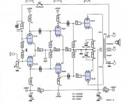
I came across this schematic which was published in Elektor 2007 but I would rather ask for some opinions about it before I start designing the PCB.
To be honest, what seems weird to me is the connection of the grid resistors of the second stage, which in my opinion should be connected to GND.
As I said, I am learning a lot so I might be wrong. Hopefully someone will explain what's happening there. I am also keen to upgrade the existing schematic eg. CCS for V1,V2 cathodes, etc.
Kind regards.
I am on my 2nd Tube amplifier project (but I have quite good SS background), and I have some 6N13S tubes which I am looking forward to use as my power output tubes.
I came across this schematic which was published in Elektor 2007 but I would rather ask for some opinions about it before I start designing the PCB.
To be honest, what seems weird to me is the connection of the grid resistors of the second stage, which in my opinion should be connected to GND.
As I said, I am learning a lot so I might be wrong. Hopefully someone will explain what's happening there. I am also keen to upgrade the existing schematic eg. CCS for V1,V2 cathodes, etc.
Kind regards.
Attachments

Thank you for your reply. So from your point of view, everything is fine regarding R7 and R8 being connected to -50V.
Regards
Regards
There are 3 low frequency poles:
input tube RC to driver tube
driver tube RC to output tube
output tube to output transformers
There also is a low frequency pole:
output tube self bias resistor and bypass cap
This many low frequency poles, and the fact that the global negative feedback from output transformer to input tube grid might possibly cause a low frequency oscillation.
Check the frequency of all these 4 poles (the output transformer primary inductance and output tube plate impedance, rp, is one of them).
The plate resistors of the input tubes are matched, but the input tube cathode resistors is 18k; not a real CCS that you already noted.
Matched plate resistors and real high impedance CCS gives equal amplitude of both input plate signals.
You might want to either use a CCS, or un-match the input tube plate loads enough to balance the plate signal amplitudes there.
I built this one about 25 yrs ago as a 'Proof of Concept'.
A more in depth article appeared in Glass Audio Magazine.
The Damping Factor is ~14, This circuit modification solves the drive problem.
Another simple version that avoids the UL OPT was also in a later Glass Audio.
Both versions have appeared here on DIY several times. 👍
A more in depth article appeared in Glass Audio Magazine.
The Damping Factor is ~14, This circuit modification solves the drive problem.
Another simple version that avoids the UL OPT was also in a later Glass Audio.
Both versions have appeared here on DIY several times. 👍
Attachments


Thank you all for your input. I am grateful for all this bits of advice and I will try to adjust the schematic in order to implement some of your suggestions.
@jhstewart9 UL OPT is not a problem, so I will attach a modified schematic later on.
Regards
@jhstewart9 UL OPT is not a problem, so I will attach a modified schematic later on.
Regards
Hello!
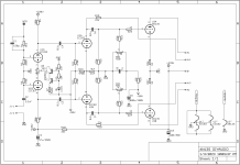
I have added the CCS for the input stage, which with the given values gives about 1.8mA for both cathodes. I have also included R5 (multiturn pot) in case I need to adjust the balance between triodes. Please let me know if there is a desired value for this trimmer.
I have added the UL connections to the V2 plates.
Finally, I have read in some places that these 6N13S tubes are not really know for good matching between triodes of the same glass, so I thought that it will be a good idea to add neg grid BIAS hence I will have the -50Vdc available anyway.
Please let me know your thoughts on this.
Kind regards.
Attachments
Fixed Bias for tubes such as the 6080 & 6N13S is a death warrant. 😱
Should always use cathode bias. Or a bias servo, a lot more complicated tho.
Cathode Bias Resistors may need to be on heat sinks.🙂
Should always use cathode bias. Or a bias servo, a lot more complicated tho.
Cathode Bias Resistors may need to be on heat sinks.🙂
I understand. Will remove the fixed bias components. I have just noticed that I have to correct some components values as well.Fixed Bias for tubes such as the 6080 & 6N13S is a death warrant. 😱
Should always use cathode bias. Or a bias servo, a lot more complicated tho.
Cathode Bias Resistors may need to be on heat sinks.🙂
1 ohm does seem a little low for a 6N13S cathode resistor.
Concerning the -50V Grid supply for the 1st two stages, note that there's a 10:1 divider so that the Grids are only 1/11-ish more negative than the 2nd stage Cathodes.
And as long as you keep the -50V supply (not everyone would ! 😉 ) the CCS Cathode supply for the 1st stage is probably a waste of time/effort/components -- 51V across the 33k resistor is going to be nearly as DC-compliant, and much lower capacitance.
Cheers
Last edited:
Hi!Fixed Bias for tubes such as the 6080 & 6N13S is a death warrant. 😱
Should always use cathode bias. Or a bias servo, a lot more complicated tho.
Cathode Bias Resistors may need to be on heat sinks.🙂
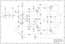
I have changed the schematic, according to your suggestions. Ideally would prefer to keep ECC82 and 83 for first 2 stages. Can you please have a look at the schematic? Is there anything else you're suggesting ?
Regards
Attachments
Do you have any suggestions ? 🙂 At this stage, I am just trying to get as much info as possible.And as long as you keep the -50V supply (not everyone would ! 😉 )
Would be nice if someone could simulate the schematic, but who knows in the future?!
Cheers
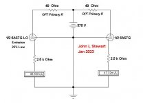
So who needs it? Cathode resisters are (mu + !) times as effective as the Rk on its own
to equalize cathode current in a PP stage. In the proposed cct Rk is much lager than rk.
The Sim shews one section of a 6AS7G 25% lower in cathode current than the other.
Balance forced by the cathode resistors is ~1%.
Attachments
If I was worried about wasting watts, I would not be designing and building vacuum tube amplifiers.
Instead, I would just purchase commercial Class D amplifiers.
Thats no fun, no designing and no building (discreet circuits and/or ICs to build a Class D amp does not excite me).
Half the fun for me is designing and building tube amplifiers.
The other half of the fun is Listening!
Listening to my different amplifier designs on my many different loudspeakers.
Enjoy the music.
And automatic grid bias makes it that much easier...
6L6? 6P3S? KT88? 6550? 6P31S with a cap? 6BQ6 with a cap? Just plug it in and go. Magic 🙂
6L6? 6P3S? KT88? 6550? 6P31S with a cap? 6BQ6 with a cap? Just plug it in and go. Magic 🙂
I'll take a look at a Sim during the next day or so. Your connexions to UL! & UL2 need to be reversed.Would be nice if someone could simulate the schematic, but who knows in the future?!
The resistors on V2 were calc for a 6SN7, might need to be changed for 12AU7 with less plate dissipation.
As Rick has pointed out the -50V supply with resistor tails would probably perform just as well as something
more complicated. I usually use -150V with resistor tails, works very well.
Very busy here this month, we P.Engs in Ontario have to get re-certified. 🙂
- Home
- Amplifiers
- Tubes / Valves
- 6N13S/6AS7G PP Amplifier schematic