Thank you for the UL connections observation and thank you overall for your support. 🍻I'll take a look at a Sim during the next day or so. Your connexions to UL! & UL2 need to be reversed.
The resistors on V2 were calc for a 6SN7, might need to be changed for 12AU7 with less plate dissipation.
As Rick has pointed out the -50V supply with resistor tails would probably perform just as well as something
more complicated. I usually use -150V with resistor tails, works very well.
Very busy here this month, we P.Engs in Ontario have to get re-certified. 🙂
I am really curious of some Sim results with the -50V supply vs -150V. Honestly, it is easier to get the -50V (bias TAP of the HAMMOND), as I already have some.
I'll take a look at a Sim during the next day or so.
That will be awesome, can't wait for it. 🙂

Assuming I'm not looking at an old schematic (dated 20:16:40, 4Jan'23, in the title box of the schematic on post #14), R11 and R12 can't be returned to Ground as long as the Cathodes are set to ~1/11 (R13 || R14 : 470 || 4k7) above -50V.
Also, C9 polarity is backwards.
And R28 and R29 will probably need to be deleted, as they are further aggravating the already excessive 'positivity' of V2A and V2B's grids.
Warm Regards
Also, C9 polarity is backwards.
And R28 and R29 will probably need to be deleted, as they are further aggravating the already excessive 'positivity' of V2A and V2B's grids.
Warm Regards
Last edited:
@Rick PA Stadel Thank you for your observations. Will keep them in mind for now, as I would prefer not to upload a bunch of schematics with minor changes.
I'd rather wait to see how the sim goes, and then update complete schematic.
@jhstewart9 Thank you for your effort. To be honest I am curious if the CCS changes the harmonic distribution graph. More specific I am talking about comparison between CCS vs. 25K resistor. I guess whichever option has increased 2nd order and less 3rd order harmonics, that is what we aim for. Am I wrong?
Cheers 🙂
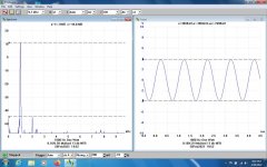
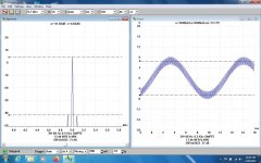
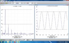
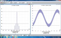
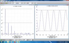
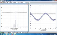
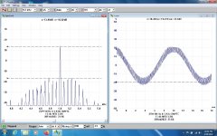
The SMPTE Test John L Stewart Dec 2021
The Society of Motion Picture & Television Engineers test is/was a very common test used to evaluate the quality of reproduction of sound amplifiers & systems. Two signals, one low frequency & another at the other end of the audio spectrum are applied to the input of the amplifier & the distortion in the output measured. This kind of test is much more difficult for an amplifier (or other network) to pass than a simple single frequency THD test.
The low frequency signal was usually 50 Hz or 60 Hz depending upon the location of the test, it was simply derived from the local power system in the test set. The high frequency signal was created by a simple oscillator on board. 5 to 8 KHz works well. Because of the way the test set worked the quality of the test signals was not very important. The result is an indication of the Intermodulation Distortion (IMD) created in the amplifier. Heathkit & others marketed IMD tester sets, quite a few are still available on the used market.
To do this test I use an LF of 80 Hz from an HP 200CD. That way it is possible to see intermods caused by the amplifier PS as well, at the PS fundamental & its harmonics, 60, 120Hz & so on. I used HF of 5 KHz from a GW GAG-810. They are combined in a simple resistive network.
For these IMD tests using a PicoScope 3224 digital SA I compare the amplitude of the 5 KHz test tone to the resulting side bands. They are separated from the 5 KHz marker by +\- 80 Hz, 160 Hz & so on. Any PS side bands will also appear if they are present.
I ran a Decware clone on the test bench, the IMD was 9.74% while the output was 260 mWatts. The Decware amp always clipped at less than one Watt.
For a point of comparison I pulled an all 2V tube PP 33s amplifier off the shelf & ran the same test. At 820 mWatts the IMD was 2.67% . The PP 33 Amp clips at ~4.8 Watts.
On a scale of Zero to 10 this version of the Decware amp might get a two from the Geezers of the 50s & 60s. But others today can decide for themselves.
An in depth description of a Heathkit AA-1 Intermodulation Analyzer is given at
https://www.robsradioactive.com/heathkit-aa1-audio-analyzer
And some are still available used on the iNet.
Attachments
-
 PPP 6080 One Watt 1000 Hz.jpg142.2 KB · Views: 77
 -
 PPP 6080 One Watt SMPTE.jpg147.8 KB · Views: 75
 -
 PPP 6080 3W 1000Hz.jpg150.4 KB · Views: 78
 -
 PPP 6080 3W SMPTE.jpg147.3 KB · Views: 73
 -
 PPP 6080 10W 1000Hz.jpg153.8 KB · Views: 76
 -
 PPP 6080 10W SMPTE.jpg153.3 KB · Views: 81
 -
 PPP 6080 15.9W 1000 Hz.jpg154.7 KB · Views: 73
 -
 PPP 6080 15W SMPTE.jpg148.6 KB · Views: 78
 -
 PPP 6080 20W SMPTE.jpg158.9 KB · Views: 78
 -
 PPP 6080 25W SMPTE.jpg173.5 KB · Views: 72
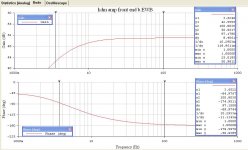
This is a problem many would be designers seem unaware of. It is sometimes called 'staggering factor'.There are 3 low frequency poles:
input tube RC to driver tube
driver tube RC to output tube
output tube to output transformers
The similar RC time constants of coupling stages together should be avoided as you have noted.
Here are a couple of examples that work put together a while ago. But need to be careful,
the OPT Low freq TC might be yet another problem.
Attachments
In order to get stability in a multi stage NFB amplifier, some designers insert a low frequency step in the response.
That is what the 3.3M resistor in the original design was meant to do. Its value often depends on the OPT used.
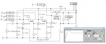
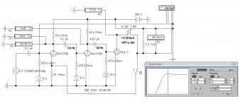
As shewn in the Sim it lifts the 12AU7 cathodes. That can be avoided by using another pair of caps in the signal path.
A circuit using the -50V PS for the Diff Amp tails looks like a very good choice to me.
The common mode tolerance & CMR looks AOK.
At that point in my investigation of the cct 25 yrs ago I authored the articles & results for publication.
I moved on, the boot strapping did what I had hoped, It is here on the shelf & gets pulled out occasionally
for more testing.
Provided the amp is operating OK, its sound ideally is controlled more by the loudspeaker used & the environment,
such as room acoustics. Many enthusiasts make the mistake of assuming their project is a part of themselves.
And lose sight of simply enjoying the result.
That is what the 3.3M resistor in the original design was meant to do. Its value often depends on the OPT used.
As shewn in the Sim it lifts the 12AU7 cathodes. That can be avoided by using another pair of caps in the signal path.
A circuit using the -50V PS for the Diff Amp tails looks like a very good choice to me.
The common mode tolerance & CMR looks AOK.
At that point in my investigation of the cct 25 yrs ago I authored the articles & results for publication.
I moved on, the boot strapping did what I had hoped, It is here on the shelf & gets pulled out occasionally
for more testing.
Provided the amp is operating OK, its sound ideally is controlled more by the loudspeaker used & the environment,
such as room acoustics. Many enthusiasts make the mistake of assuming their project is a part of themselves.
And lose sight of simply enjoying the result.
Attachments
If I were building this project as usual curiosity would play a part.
I'd build in both the SS tail & a 25K resistor tail for the 12AX7 stage.
That way it is possible to make some comparative measurements.
And listen to the amp both ways on the same source & speakers.
Is there a difference that is audible, why is it there? 😀
I'd build in both the SS tail & a 25K resistor tail for the 12AX7 stage.
That way it is possible to make some comparative measurements.
And listen to the amp both ways on the same source & speakers.
Is there a difference that is audible, why is it there? 😀
Hello everyone !
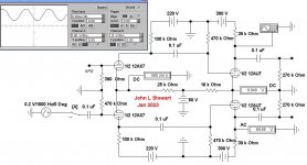
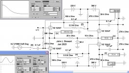
Based on the comprehensive info I had from @jhstewart9 I have redrawn the schematic.
Please let me know if everything is fine with the schematic, or if I have missed something.
Kind regards
Based on the comprehensive info I had from @jhstewart9 I have redrawn the schematic.
Please let me know if everything is fine with the schematic, or if I have missed something.
Kind regards
Attachments
In this circuit about 1/3 of the HV supply appears across the cathode resisters,
If the HV supply was 300V then there is 100V across the bias resister.
Watts = ( E Squared ) / Rk, so ~ 10000 / 1250 or 8 Watts.
Most designers double that for safety. The next larger commercial size is probably 20 to 25W.
I bought heat sinked resisters & mounted them on the inside of the aluminum chassis.
People building this particular circuit should keep in mind some of the interstage
coupling values on my schematic may not be optimum for whatever OPT is used.
Thank you for reply. The cathode resistor in 2.5K. That means:
Watts = ( E Squared ) / Rk, so ~ 10000 / 2500 or 4Watts.
Am I right?
Watts = ( E Squared ) / Rk, so ~ 10000 / 2500 or 4Watts.
Am I right?
That is OK. Don't know why I picked 1250R
Just got off the tractor here, we are getting quite a bit of snow.
Not like Buffalo tho!
Just got off the tractor here, we are getting quite a bit of snow.
Not like Buffalo tho!
Hello
I have completed a PP amplifier based on russian equivalent 6N13S. Schematic is different, I have used 8pin valves. They are the russian equivalents of 6SL7 and 6SN7 (6N9S and 6N8S).
First triode of 6N9S makes the input stage, and second triode is cathodyne phase splitter. Then the 6N8S is a voltage amplifier followed by the 6N13S output stage. Both triodes of the output valve work in PP with cathode bias.
I have measured 11.5W rms before clipping. THD+N is 0.7% for that power. 6dB of NFB applied.
It’s been the main amplifier for over 6months now and it is my favourite. I also had PP EL84, PP KT88.
I have also designed a line preamp based on 6N9S which pairs perfectly with this amp.
Are you planning to build something around this power tube?
Regards
Here’s a photo of the finished amplifier.
Attachments
Wow - that looks great! Well done 🙂
I have an existing chassis and am looking to use one 6SL7 as pre-amp for both channels, ie one triode either side. Then 6N1P to provide phase splitter/inverter which then feeds 6AS7 for PP. I have a 15w PP 3.4k OPT to use.
I already started a thread on diyAudio about the design, but came across your thread whilst searching.
About the phase splitter, I preffer cathodyne. A bit more distorsion but mainly H2 which is good. That is actually one of the reasons why I have changed the initial project.
Another reason is that it was easier to design the pcb with oktal sockets. The 9pin tube sockets have different height than the 8pin ones.
Btw, here’s a shot from inside the amp.
Regards
Another reason is that it was easier to design the pcb with oktal sockets. The 9pin tube sockets have different height than the 8pin ones.
Btw, here’s a shot from inside the amp.
Regards
Attachments

Hello, there is a posibility of me acquiring 6n13S tubes in near future. So it got me searching for a schematic to build an amp based on them. Because of that i stumbled upon your thread. Do you mind sharing the final schematic, the one based on octal tubes? Even if i won't build it, having something more to analyze, would be nice, as i could possibly make my own spin-off based on yours. Also, very neat amp, I really like it ^^.
- Home
- Amplifiers
- Tubes / Valves
- 6N13S/6AS7G PP Amplifier schematic