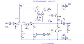

R5 and R16 is a voltage divider.
This reduces the gain much too much.
Make R5 be 1k.
So this would make the signal be 10/11 at the input. And not only 10/13.3 Volt.
I don't think C13 is necessary. How come you have put this capacitor in? I have not seen this before.
Otherwise the amplifier looks alright to me.
This reduces the gain much too much.
Make R5 be 1k.
So this would make the signal be 10/11 at the input. And not only 10/13.3 Volt.
I don't think C13 is necessary. How come you have put this capacitor in? I have not seen this before.
Otherwise the amplifier looks alright to me.
Remove D3, it has no function.
Add a bleeder resistor (100k) in front of C12, avoids rough things when connecting sources.
Q1/Q3 are running on low, have R2 at approx Vsupplyminus/1mA = 33k; lower R11 accordingly.
There's just enough open loop gain.
Add a HF zero cap in parallel with R16 (set to ~<100kHz). Ditto for R14 one octave higher.
Reverse the Zobel: R19+C5 in front of L1//R27.
Keep in mind: the 5200/1943 are a rock solid combo, but does not guarantee a rock solid amplifier.
Last edited:
Good idea Lineup sir.You can improve the input stage.
U6 is a current source that gives like 2mA.
U1/U2 is a current mirror.
I will try this.
Use low voltage types like BC337-40 for U1,2. I never see why anyone uses high or even high-ish voltage types there, when hFE at 0.65 (or less) volts Vce is a primary driver for mirror performance. With 150 volt parts, this is always compromised.
Of course for a junk box project you use whatever is on hand, but given a choice there is an optimum one.
Of course for a junk box project you use whatever is on hand, but given a choice there is an optimum one.
How???D3: perhaps an attempt at aprox temp comp for Q1 and Q2?
It's still unclear what D3 is doing there, except for preventing the input differential to incinerate if the supply voltages inverse by a earth magnetic pole swap.Schematic updated.
Q1 draws it's base current from R16 (10k), so it's on a small but negative voltage. Q3 will balance that. Hence, C3 should have the plus node to the ground.
Depending on the beta of Q3, the output offset is just above or under zero volt.
Q9/Q8 (BD139/BD140 are just capable of driving the 5200/1943 combo. Their beta's can go down to 60 at idle current, leaving next to nothing at rated output levels.
Q4 (BD140) is a challange. Operational... simulations won't bother... should be a BD140-16 (beta=160-up)... or much better. It's the core part of the amp.
Q10 needs a base stopper. To find out why, just drive the amp to clipping (with an expendable or very large speaker).
Ok ok, I’ll tell you. When Q10 saturates it will drag down the voltage across the two diodes and cause the input stage to latch up. You have no idea how many things I threw across the room trying to figure it out for the first time.
Ok ok, I’ll tell you. When Q10 saturates it will drag down the voltage across the two diodes and cause the input stage to latch up. You have no idea how many things I threw across the room trying to figure it out for the first time.
Good idea Lineup sir.
I will try this.
Do it.... equalise the currents through the differential input pair... always.
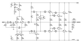
С10 it is better to replace it with a non-polar one with a capacity of 1 µF.Last project
- Home
- Amplifiers
- Solid State
- 2SC5200 A1943 Amplifier