Hi,
I want to improve some components of my crossover and I would need information. I attach the diagram to better understand. The crossover is in two parts.
The first part of each lane is at the bottom of the enclosure (to the left of the dotted vertical line)
The second part (to the right of the dotted vertical line) is located at the top of the enclosure near each driver and is connected by a cable with the bottom part.
Is there an any advantage to separating and placing only this part of the crossover close to the driver?
Also, in the diagram at the bottom right, is a circuit connected in parallel with the input terminals. What is the purpose of this circuit?
I want to separate the mid-tweeter and the woofer to be able to go in bi-amplification, do I need to make a copy of this circuit
to have one for the mid-tweeter part and the original for the woofer? or is this circuit is usefull for the woofer or mid-tweeter only?
Thanks
Attachments
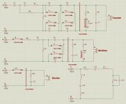
@Dante The circuit at the bottom right is a conjugate network to level the impedance variations of the system. You could do without that entirely, probably, ......if your amplifier(s) are solid-state and low output impedance.
The rest of the crossover can be electrically separated just as shown in your drawing and the sections driven individually.......if you want to. (There's not much benefit in doing that though.)
I think maybe I'd just leave the system alone. It looks like a good design to me.
Dave.
The rest of the crossover can be electrically separated just as shown in your drawing and the sections driven individually.......if you want to. (There's not much benefit in doing that though.)
I think maybe I'd just leave the system alone. It looks like a good design to me.
Dave.
@Galu It is from a Dynaudio Contour 4
@Davey Thanks for the informations. I dont't want to change the values of the crossover but only replace
capacitors and resistors for some better parts with same value.
For that, I need to construct a new crossover but with more space to be able to fit some bigger parts and that it's why I was asking if the section of the crossover placed to side of the drivers have some importance or I could put all sections on the same board and this way I could remove a section of cable per driver.
In the crossovers for the Tweeter and the Midrange, what are the sections that have the Capacitor on both Pos and Neg, cross-bypassed with inductors? Do those change the phase by 180deg?


I dont't want to change the values of the crossover but only replace
capacitors and resistors for some better parts with same value.
I'm with Davey on leaving well enough alone.
I can't see that Dynaco will have skimped on the quality of the components in this 10,000 dollar speaker's crossover.
Furthermore, changing capacitors for different types, e.g. electrolytic for film, can upset the intended voicing of the speaker.
Thats what I thought. Time delay and phase shift, to time align the tweeter and midrange and better integrate.
This is definitely not a simple crossover.
Dante - given the above, I would be very wary changing out any electrolytic caps in this crossover, because of that complex time alignment framework. Electrolytics has ESR that varies based on freq. Swapping those out for non-electrolytics could really mess it up and sound much worse.dont't want to change the values of the crossover but only replace
capacitors and resistors for some better parts with same value.
This is definitely not a simple crossover.
All the capacitors in this crossover are originaly Solen polypropylene at the exeception for two capacitors for the tweeter that are in polyester, no electolytics.
My first idea would be changing all the capacitors with the Clarity Cap CSA and CMR series and the Path Audio for the resistors.
Those parts are so big that I need to construct a new crossover board to be able to received them. In the same time why not including all the sections in a single PCB.
I would also have liked to change some coils to Litz coils, but I don't have the knowledge to recalibrate the Tweeter section to follow the Midrange and Woofer.
I could have a Litz coil for the Woofer, all I need for the Medium is lowering the resistor in serial with the coil to match it with the woofer, but for the Tweeter, the the RC circuit give me some trouble it is not so simple for me to recalibrate this circuit.
Perhaps if you were following RF principles it would make some sense. In this case it's not likely to be critical and you can move them around if you need to.Is there an any advantage to separating and placing only this part of the crossover close to the driver?
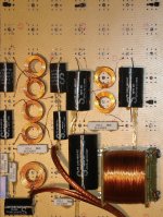
Is there a picture of the double coils in the crossover. Are they "double coils" really in the same component interacting each other in different directions? How to simulate that in Spice?
Thats good. Makes it easy then. Much more linear., no electolytics
I am curious to see how you perceive the sound if you decouple the woofer from the Tweeter and mid, and leave out that extra impedance balancing circuit.
Is there a picture of the double coils in the crossover. Are they "double coils" really in the same component interacting each other in different directions? How to simulate that in Spice?
The coils should be separated not coupled.
@jayme You could be sure I will try it. I will gives my impression later.
I'm sending to everyone a picture of the original crossover.
Today I've go to Solen to show them my crossover and explaining that my initial wish was to replace all the coils with Hepta Litz coils,
the resistors and the capacitors. They answered me why not?
They will measures and entering in their system all the parameters (Values, DCR etc) of each parts to be able to see what exactly my crossover is doing
and after that they will replaces all the coils with hepta litz and re-calibrate the crossover to have the same end result of my original one.
Attachments
Not really, since the original crossover will remain intact. I'm going to build a new one, with new parts and that way I'm going to be able to compare
the old to the new. The original design will remain the same, but with a lower DCR for the coils, resistors and capacitors values will be somewhat modified to rebalance the whole. Of course, if it's possible. Otherwise the coils will remain the same and only the resistors and capacitors will be replaced with better. Or maybe there's something I don't understand, don't hesitate to explain it to me.
In the worst-case scenario, I'd have invested money for the new parts, but I can take the risk.
- Home
- Loudspeakers
- Multi-Way
- Dynaudio crossover questions