Paraflex & Super Planar High Order Compound QW & Compound Horn variants /dev/builds
The builds you will see in this post are based upon designs provided by yours truly
😀 and skillfully handcrafted by a man named J.R Vansickle of Paragon Concept audio in North Carolina ... Mr Vansickle has excellent woodworking skills, a great ear, and also a strong background in Home/Audiophile & Car Audio
😎 ....
The compound loaded concepts discussed within this post started off as a configuration that had repeatedly proven itself to be viable (and practical) in simulation, so it became apparent to me that this was something worth exploring.... During this time Mr Vansickle was coincidentally receiving many requests for PA cabinets....
We had already worked together on a few designs that turned out well in the past, and now it was time to try something new

The compound loaded simulations looked like they would deliver exactly what the application called for so Mr Vansickle built the first set and they worked like a charm! .. ... A few of these successful designs are currently in use by a few of Paragon's customers in the Eastern United States ..... If the cabinets did not sound right to his ear we would have fallen back to simpler designs for the customers but the first set of these that he built sounded fantastic, so we went with it!

At this moment there are no detailed measurements, only a few crude approximations and a few low-res videos of them in action, but that should be remedied as Mr Vansickle has vastly increased his commercial shop space (new location) and is about to be outfitted with some gear that will be able to produce the detailed measurements that we sound fanatics desire
🙂 ..
First of all to be fair i have to say that this is not a new idea by any means, compound horns have been around for a long time so i cannot take credit for that

..... It is an old idea but sometimes old ideas are worth revisiting because new levels of performance are made possible with the use of modern drivers and modern software

..
In other parts of the world some people have recently constructed 6th order subwoofers and bass cabinets that they call "Planar Wave Horns" , the plans have been floating around for a while but the popularity has not caught on here in the United States as far as i can tell ....... I pondered that higher performance might be possible if i swapped out the rear resonant chamber/vent set in the Planar Wave Horn design and replaced it with a true quarter wave resonator (with or without expansion) ..... I tried this out in Hornresp (and yes you can do this in OD mode it just requires some creative usage of a vented rear chamber

)..
The result is that you can utilize the resonance of the smaller chamber tuned to a higher frequency to fill in the dreaded response "hole" which typically plagues Back Loaded Horns , Rear Loaded Horns , TLs (QWPs) , Scoops etc .......... It is interesting that filling in this "hole" not only increases the usable bandwidth but also seems to improve general efficiency just a bit as well ....
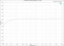
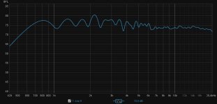
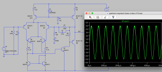
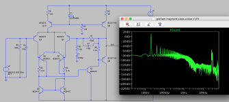
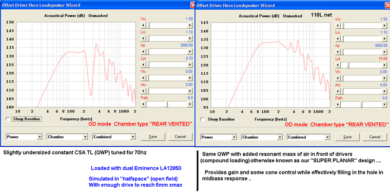
Here is a generic sim to demonstrate this useful effect:
As it turns out the bandwidth can extend well beyond the "hole" that we filled in with our upper resonance ..... This makes it possible to create something like a high performance Kick-Bin cabinet with bandwidth that extends surprisingly high ....
OR
If gain and output take priority over bandwidth (as it might in a subwoofer design) then you can make that upper tuned chamber larger or longer which increases efficiency of the system while sacrificing bandwidth ......
Note: I have been calling this upper tuned chamber the "front chamber" or "MF waveguide" for lack of a better term at the moment .... and I have been calling these designs "SUPER PLANAR"
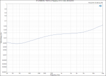
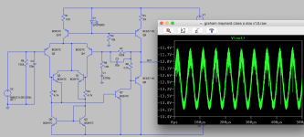
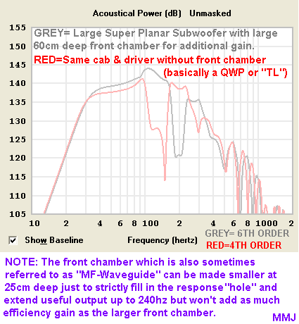
Here is a generic example of a subwoofer based upon this design can do:
This design can under the right circumstances compete directly with Front Loaded Horn and Tapped Horn designs of the same cabinet volume and tuning, loaded with the same driver but only if the driver has the appropriate T/S parameters for this design ...
In the case of a low tuned subwoofer loaded with a large diameter driver the cabinet volume requirements can be quite large unless you choose a driver with high motor force (relative to the diameter of it's diaphragm) and this sort of thing simply wasn't possible back in the 1930s (or whenever it was when the first compound horns were devised) ...
We will revisit this idea as a subwoofer later because we did produce a set and they work well , but for now we shall go back to kickbin designs because that is what we started with and we don't want to get ahead of ourselves ....
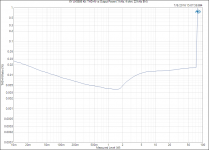
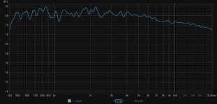
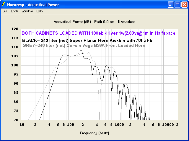
To demonstrate how the Super Planar can compete directly with a FLH (or Tapped Horn in some cases) here is the CV B36A (which i use for a kickbin) compared to the Super Planar using the same 188EB driver and the same cabinet volume .... I prefer the Super Planar's response here ..
Not bad eh?
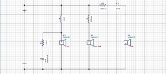
😀 Ideally the upper response would taper off and produce something roughly resembling a "house curve", but technically due to the 18" driver this one will be limited on the upper end (certainly no higher than 500hz without becoming too 'beamy").. ....... There is a way to have some amount of control over the contouring of the upper response, and it can be seen as a
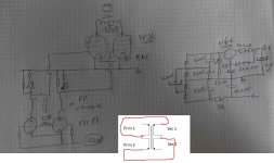
red panel in the following sketch .. More explanation on that later with accompanying Akabak modeling to demonstrate alterations in the response contour ......
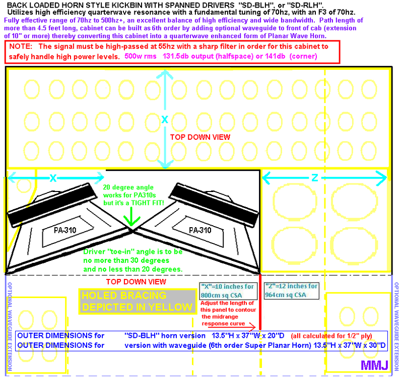
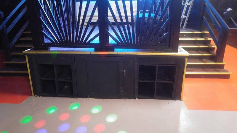
Here was the sketch I came up with for J R Vansickle's very first SUPER PLANAR build! This set worked very well and ended up being used as Wideband Kickbins in a night club sound system installation located in North Carolina ...
As you can see this sketch originally gave us the option of building it without the front chamber (waveguide) which would have made it a plain offset-driver Back Loaded Horn but with the front chamber included it becomes a Super Planar BLH.
The red panel can alter the midrange contour considerably but at the time Mr Vansickle wasn't set up to take detailed measurements so we left the panel at 50% depth of the waveguide because we knew that it would produce sufficient results ... With dual Dayton PA310 drivers the response reached reliably up to nearly 1khz ! We were pleasantly surprised by this

.
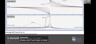
I modeled this in Akabak in an effort to get an idea about how the contour would be altered by changing the length of our red panel ... I suspect these curves are a bit exaggerated (i did squash them vertically) but it gives you an idea of what is possible .... We are calling the red panel the "H-Panel" in this comparison...
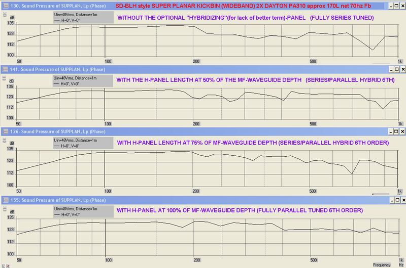
I used a very non-scientific method in an attempt to get an idea of where the dips and bumps in response really landed in the real world cabinet ... I did this by running Mr Vansickle's recorded low-res cellphone video files (of multiple music tracks being played over these speakers) past my software RTA in peak-hold mode ...... I am happy to say that there doesn't appear to be any holes in response but there is what looks like might be a bump between 250hz-280hz and a dip centered around 310hz followed by another dip around 500hz but it is hard to say if the anomalies were just a feature of the music being played or some room interaction or boundary bounce or something else like the response of the microphone on his cellphone ..... Like i said it is the furthest thing from scientific
🙄 but promising.

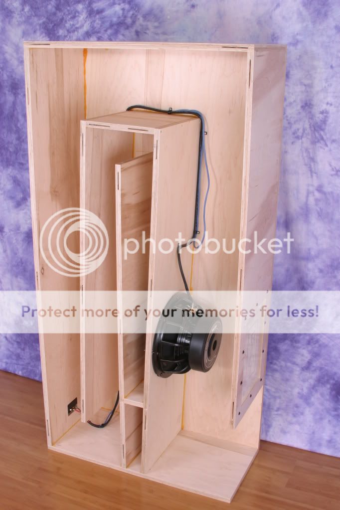
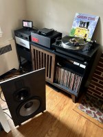
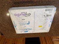
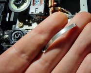
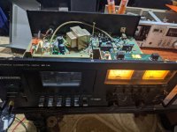
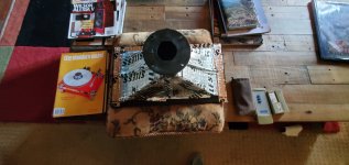
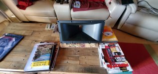
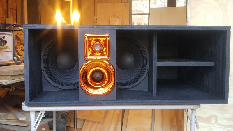
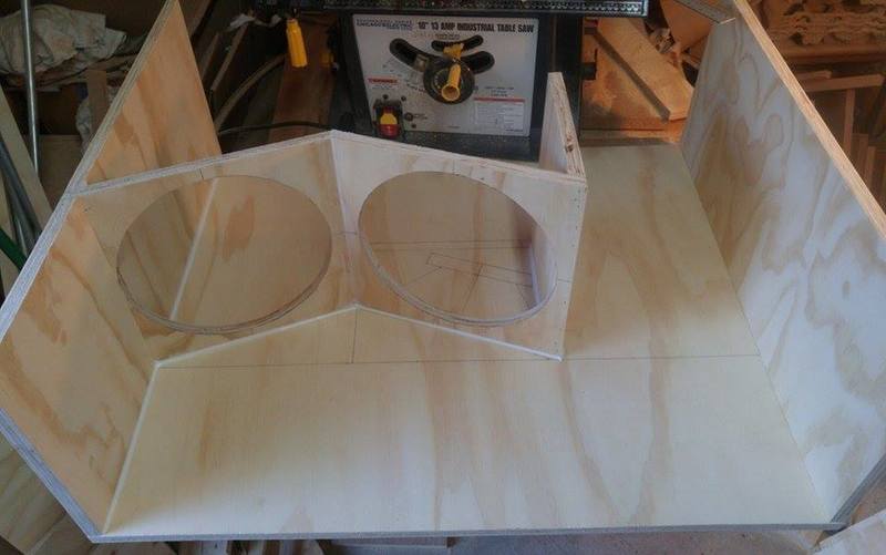
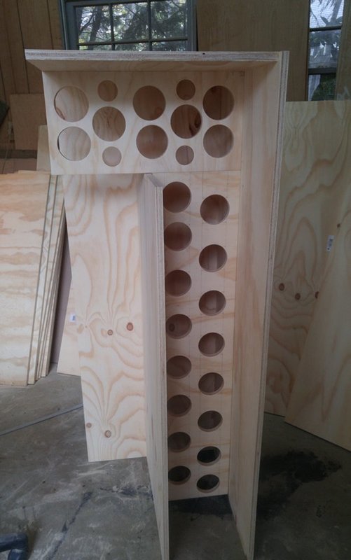
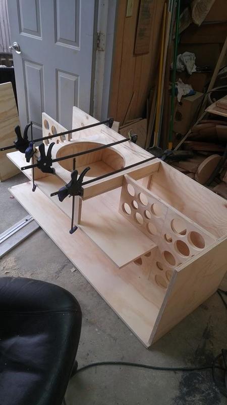
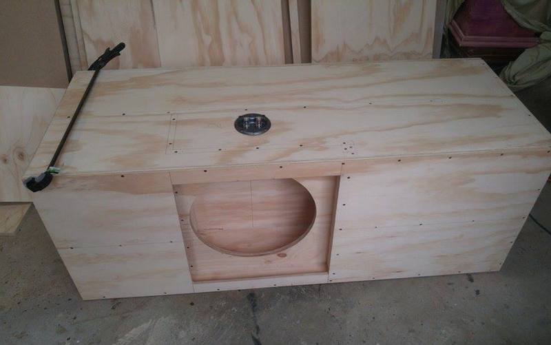
Lets move on to some build photos:
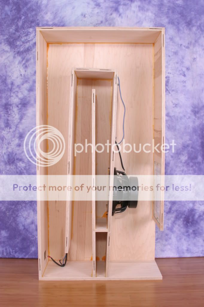
He made this cabinet out of 3/4" ply (the dimensions were calculated for 1/2" ply , so needless to say the 12" drivers fit VERY tight but he made it work

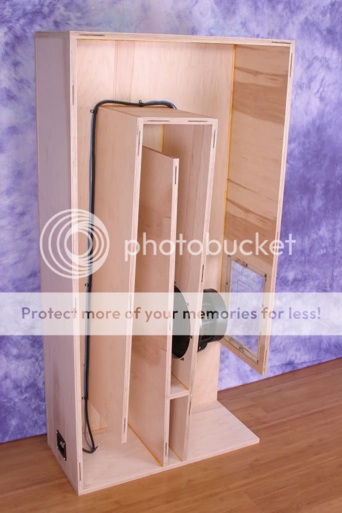
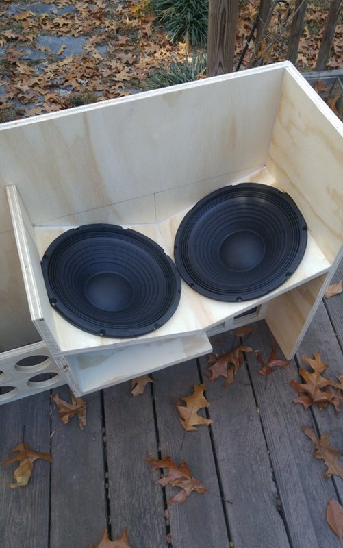
You can see some more of the internal bracing on this next photo
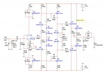
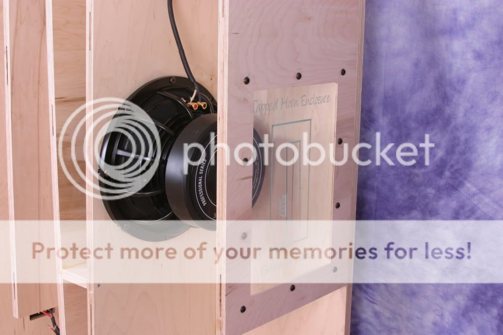
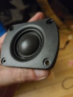
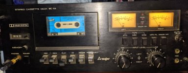
These are 3-way cabinets with a Selenium D250X midrange compression driver coming in at right around 1khz and a Selenium D220Ti coming in at around 4khz-ish ...... The PRV horns that we put these drivers on produced responses that were very far removed from published curves
😱 (and this was obvious even without detailed measurements) so we had to redesign the crossover .... The woofers were actually run "Dry" and i didn't want to go into too much detail about the crossover network here (since it is unrelated to the compound loading concept) but in the end our filters were kept simple and sweet......
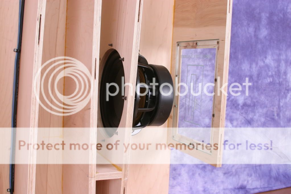
NOTE: Without the recommended HL14-25 horn the D250X does not want to reach very low.... In the PRV horn that we used there was a tremendous honk at 1khz, and if we reduced the series capacitance enough we could tame that 1khz bump however when set up that way there was no chance of significant output from it much below 1khz, so it was a good thing that the PA310s had no problem reaching up to that range despite the fact that they were recessed behind the waveguide which composes the front chamber on this cabinet .......
ANOTHER NOTE: On the PRV horn that we used the Selenium D250X is very loud (as if we traded some bandwidth for efficiency perhaps) and so it did require some padding/attenuation to better match the 220Ti and the parallel PA310s..
YET ANOTHER NOTE: We found that the D220Ti needed to be phase flipped in order to integrate smoothly with the midrange ..
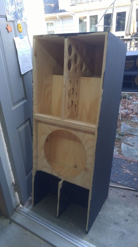
AND NOW FOR SOME SUBWOOFER CABINETS
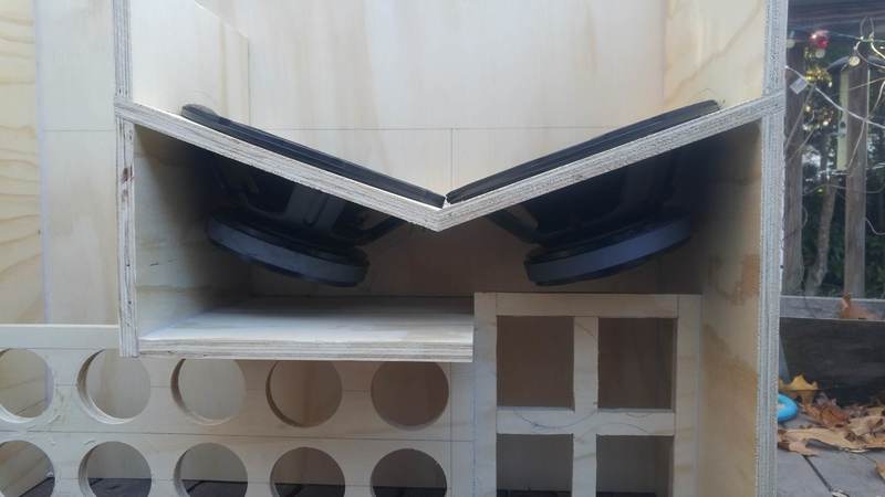
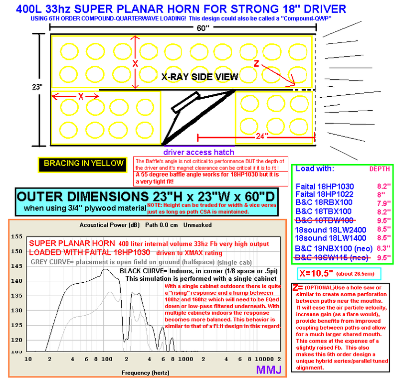
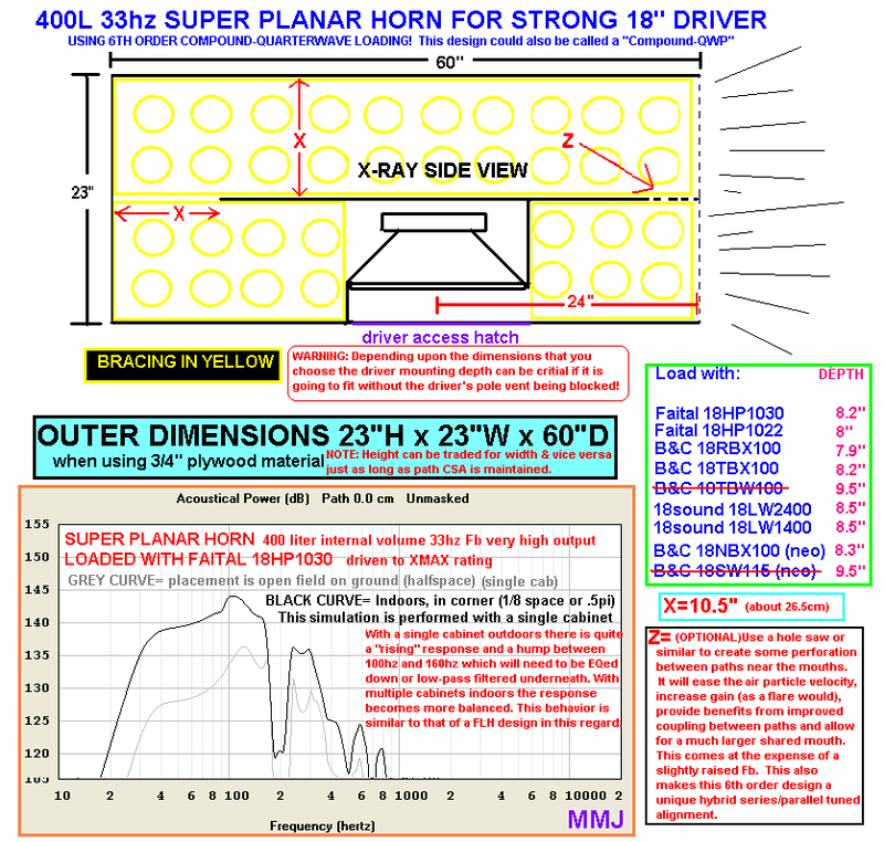
The goal was to build some subwoofers that could fit underneath the stage.. These would be installed at the same nightclub where the Super Planar tops were going to be used .... There was 23" of vertical clearance underneath the stage, and a heck of a lot of depth that we could utilize ....... Due to the height limitation and the design of the cabinet we knew it was going to be a tight fit for the driver so we came up with a few different baffle shape options ....
Mr Vansickle chose the "S" shaped baffle in the following sketch
We went with a Faital Pro brand driver but there are many more options that will work as listed on the right, some are crossed out because their excessive mounting depth means that they won't fit unless the box dimensions are made taller . ...
Many (if not the majority of) PA sub applications don't require such a low tuning , so in that case the cabinet would not need to be 60" deep, the path can be shortened a bit....
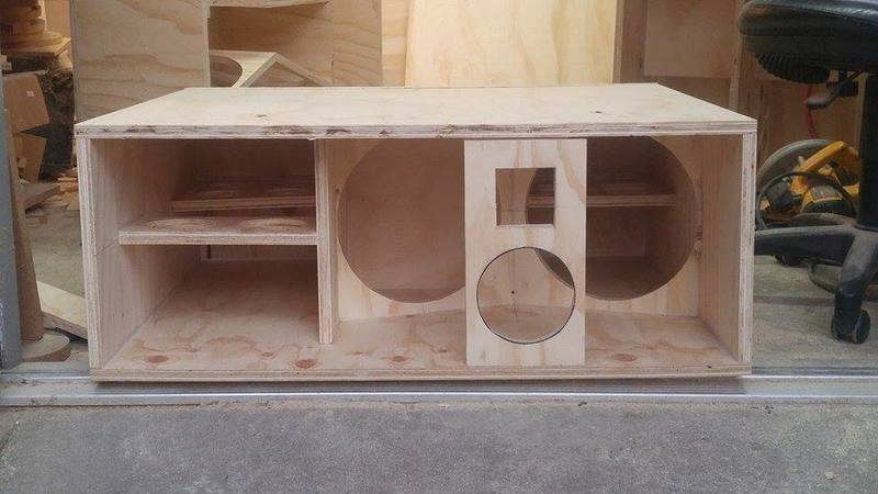
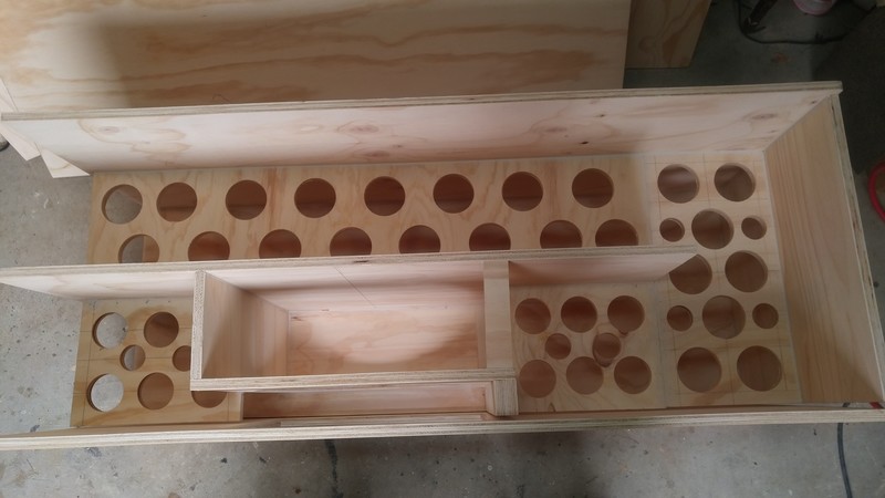
. These are some BIG boxes!
😱
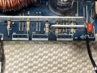
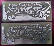
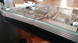
Lovely holed braces
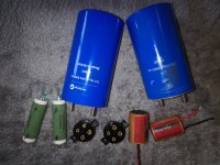
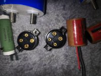
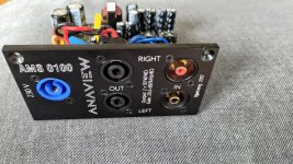
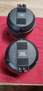
Yes yes, I know ... He chose this banana jack binding post set (instead of Speakon) for a good reason i am sure, possibly having something to do with the tight quarters underneath the stage ...