Discrete 4x1.5V Battery Headphone Amp, Lowpower

It works down to +/-2.0V.
Distortion is low and current consumption is only like 3-4mA depending on the status of the batteries.
Has been tested in simulation with 32ohm and 300ohm load.

I challenge everybody to try to design a real lowpower headphone amp for +/-2.0V.
Post your schematic here.

Lowvolt Battery Headphone_03.jpg

Resistive port cardioid active speaker insipired by D&D 8C

Hey guys,
Actually, I've been keeping an eye on D&D 8C active monitor speaker for a while now and after Erin's Audio corner YT review, I'm tempted to try my luck designing a similar active speaker to see what would come up at the end.
I have access to many sample drivers so it's needless to buy drivers in the first place. I'll use Hypex DLCP with some Ncore NC252MP (rated 250watts@4ohms). I have also miniDSP 4x10HD if needed. For now, my biggest concern is about maintaining a controlled cardioid pattern from about 100hz give or take for the midbass/midrange driver. I'll use one or two subwoofers at the rear side as boundary coupled bass drivers just like 8C. I have also some options for a tweeter that I think will be of lower significance for now. I'll take care of that later.
It will be a big profile bookshelf type of speaker, not a floorstanding.
Hary F. Olson has an article "Gradient speakers" AES Volume 21 Issue 1; January 1973 I'm sure I had downloaded it many years ago but can't find it on my laptop and I have no active membership for now. If anybody has access to this article I would be grateful to have it. It would be much of help to read that article.
For now, I'm thinking about some drivers. for subwoofers, I'm considering SEAS L26RO4Y. I don't know one or two. I'm gonna have two on the prototype enclosure so I can test both ways. I have no smaller than a 10" driver for this region. for the midbass/midrange region I have a couple of choices. this is the most critical driver within others. Due to gradient cancellation, it will have about 6dBs lower SPL so a high dynamic and high excursion driver is more suited to have the same acoustic output after the cancellation. A driver with resonance frequency close to the lowest midbass frequency will be needed and I may have to use some EQ to boost lowers frequencies to have a flat response around 100hz.
I've never design anything with a flow resistor port to get a passive cardioid pattern. I'm gonna use polyester felt, natural ship wool or Ecco felt, I don't know for now. I have not much idea about the port itself. I have to figure a way out to measure the delay needed for phase cancellation. I think it could be measurable by the impulsive response in the time domain but I have no idea about the size of the port and the ratio between it and the SD of the back of the diaphragm.
Faital Pro 8PR200 and 10PR410 are my first choices. High excursion and good dynamic range. there are a pair of SEAS U22REX/P-SL also available. I have also Beyma 12P80ND but I think that would be oversize for the project. for the tweeter, I'm considering Beyma TPL-150/200H or Aurum Cantus G1 or AST25120 or maybe a BlieSMa T34B with a waveguide. I have a 3D printer at hand and can print a waveguide for the dome if needed.

that's it for now. I will make my mind and any idea is much appreciated. I'm totally new to this kind of speaker design so I like to hear opinions. I hope in the end it will be a good project with justified and measured results so anyone interested could build it as a DIY.

ICEpower 125ASX2 Measurements and Mods

I've purchased several of the B&O ICEPower 125ASX2's. The bass is astoundingly granite solid, but the rest of the range wasn't as good as my Hypex amps on my Quad ESL63's. This weekend I decided to put my ears away and strap on my engineering hat and try to understand the differences between my three switching amps (tripath, ICEPower, and Hypex)

I started by inputting a logarithmic sweep into each amp and measuring the output across a 7.5ohm wirewound resistor and measuring the output. I then calculate the difference between the input and output. After I have that "baseline", I then replace the resistor with the Quad ESL63 (which is a nasty reactive load) and repeat the measurement. This was my zero order starting point before I started looking at distortion spectra.


One of the differences in these switching amps is that some change their response with the changes in load (Tripath, I'm looking at you).


Anyway, I saw something horrifying with the ICEPower amp, the treble was rolled off significantly, as you can see in amplifier frequency response graph below.

I've added a potentiometer at the input of the amplifier, and it turns out that the input impedance of these ICEPower amps drops significantly with rising frequency. At DC, the input impedance is 270K, at low frequencies, it drops to about 27K, and at 20KHz it's below 6K. This means that the amp needs a low output impedance source to drive it The beauty of these amps as I saw it was that they were complete with only connectors and an enclosure needed. But it turns out that a simple volume potentiometer put in front of the amp messes up the frequency response significantly.

As seen below in the input schematic, there is an anti-aliasing filter, I unsoldered the grain of salt sized capacitors and the input impedance got much more stable. The input impedance graph on the left shows the input impedance with and without this filter.

I'm building an Op-Amp buffer stage to go between the potentiometer and the amplifier input. The op-amp stage will be powered from the auxilary output of the amp itself.

Keep this "feature" in mind when you consider this design.


Sheldon

Attachments

  • ICEPower Input Impedance.png
    ICEPower Input Impedance.png
    23.2 KB · Views: 7,120
  • icepower_frequency_response.png
    icepower_frequency_response.png
    23.5 KB · Views: 6,509
  • icepower_input_circuit.png
    icepower_input_circuit.png
    54.2 KB · Views: 6,744

Hi, I'm Gesualdo

Hi everyone,

My name is Gesualdo, and I’m excited to finally join the diyAudio community

I've always had a passion for electronics. Although I’m a qualified electronics technician, I’ve never worked in the field professionally. My knowledge is therefore somewhat limited, but I’ve always managed to get by thanks to curiosity and enthusiasm.

I’m particularly interested in analog audio and amplifiers. In recent years, I’ve repaired a few solid-state amps, but I’ve never had the chance to work on tube amplifiers. I’d really love to hear how they sound in person!

So far, I haven’t tried working on tube amps mainly because I still feel I have a lot to learn. But I hope to grow here with you—by reading, learning, asking questions, and maybe one day building something of my own.

Best regards to all!

Cheers!

Proof of Concept: DSP Amp with 2x TAS3251

TL;DR: A friend and I are developing a DSP amp and are seeking feedback on our proof of concept.

Note to admins: This post is not intended for commercial purposes. I have deliberately avoided advertising any brand or product names. The sole purpose is to gather feedback for our feasibility study on a project that may potentially become commercial in the future.


Dear fellow engineers and enthusiasts,

This is a prototype of our audio amplifier, which is based on the ADAU1452 DSP and two TAS3251 chips in the output stage. This setup provides a total output of 4x175W (or 2x350W) at 36VDC.

After several months of development, we now face some critical decisions, the most important being the viability of this device for mass production and the potential features to add or remove since this proof of concept.

This version is not the final iteration; we are still optimizing certain parameters. Most notably, the THD+N currently measures at 0.08% at 100W into 4Ohm and 0.008% at 10W into 4Ohm, with an A-weighted noise floor around 105uV. While these numbers are quite good, they do not fully match the TAS3251 datasheet. We are continuing to optimize the PCB layout, LC filter components, and PFFB.

We aim to provide plug-and-play functionality for this device, meaning users will not need to tweak the ADAU DSP and can select one of the pre-made use cases that are easily configurable and controlled via a user interface. For more advanced users, full access to the ADAU DSP will be available using SigmaStudio.

The main firmware, based on FreeRTOS, runs on an STM32F4 MCU. This MCU initializes and controls the DSP and amp chips, among other functionalities on the board. The audio signal path is also managed through the MCU, allowing for various measurements such as level metering and FFT. Additionally, the MCU handles USB audio input and the user interface.

We are also considering integrating 3rd party module to significantly enhance connectivity and streaming capabilities.

Our current focus is to prepare the hardware fully, so all new features can be added or enabled simply by updating the firmware in the future.

Please share your thoughts on how appealing this project is to you and what features you would like to see added or removed. Your feedback will be invaluable in guiding our next decisions. Below is a detailed list of features.

Thank you!


Notable features:

Inputs:

  • I2S
  • SPDIF
  • Bluetooth with aptX
  • USB audio class

User interface:
  • GPIO and Rotary encoders
  • All features controllable over I2C registers and through SCPI interface on UART
  • Few RGB LEDs on board

Powering:
  • 36VDC up to max power
  • USB-PD up to 100W (up to 240W in the future once the technology becomes available)

Connectivity:
  • Point-to-point stereo link with another module using CC8520
  • Integration with third-party module for streaming services such as Spotify, Apple Music, Amazon Music, Tidal, Deezer, Qobuz, TuneIn, and more...

Upgradability:
  • Main firmware upgradable over USB
  • USBi interface emulated by main firmware, allowing real-time DSP tuning and debugging without a dedicated hardware programmer

Attachments

  • amp2.jpg
    amp2.jpg
    545.3 KB · Views: 496
  • amp3.jpg
    amp3.jpg
    549.9 KB · Views: 435
  • amp1.jpg
    amp1.jpg
    546.1 KB · Views: 442

IanCanada's Latest RPi GB Goodies Impressions... and your tweaks, mods and hints...

I've had a bunch of the goodies from Ian's latest and greatest Group Buy on hand for a bit over a week now, with various combinations making music since this last Monday. NONE of it is broken in yet and I have a LOT of combinations and variations to try still... so no impressions to post YET.

BUT I'm starting this thread as a way to gather impressions and info about his GB RPi goodies... the FiFoPi, various DACs and I/V / output stages along with the ESS DAC controller, the LiFePO4 supply, the updated IsolatorPi, and a bunch of supporting accessories.

Anyone got any sonic impressions or tips they'd like to share.

Me, I'd like to get through a few more of the permutations I'm planning to try before starting to share how they work. PLUS I still have bits and pieces arriving... LL1544a's AND LKS discrete opamps both delivered today. A few more orders are yet outstanding. AND a few more to get in.

I'll update at some point what I've got and what I'm trying.

In the meantime, post away!

Greg in Mississippi

P.S. Anyone got any good alternative clocks worth trying? I have 22/24 & 45/49 Crysteks AND various NDK's... 22/24 & 45/49 SDAs, selected 90/98's from Acko, and a TON of standard SDs. Anyone got a good source for high-grade Connor-Winfield's or other possible alternatives?

Crossover help

Hello everyone,

So I am trying to build my first speakers, and I got stuck (obviously) with no idea why predicted crossover and real implementation is way out of acceptable range?
I will attach program I've used and response graph and photo ,of loose and glued implementation. I do hope for help. Thanks in advance

Attachments

  • image_2025-04-06_105129539.png
    image_2025-04-06_105129539.png
    396.7 KB · Views: 66
  • Basta M cros.png
    Basta M cros.png
    339.8 KB · Views: 64
  • d615e269-ae43-49e1-94ac-ddf9468f7f41.jpg
    d615e269-ae43-49e1-94ac-ddf9468f7f41.jpg
    168.6 KB · Views: 62
  • 776a2545-8100-434b-8f1b-ec1bf5f8a500.jpg
    776a2545-8100-434b-8f1b-ec1bf5f8a500.jpg
    141.4 KB · Views: 68

New member

Hello, I'm a new member in this forum and I'm really interested in building my first kit speaker. Since I'm very unsure about whether I should get this one, I'm curious about opinions and thought this forum might have the most members with opinions about it. I just started this DIY journey and am learning about parts, drivers, crossovers etc and want to learn about what components might improve the overall performance.

GM Audio Class D 4 channel 2400.4 info ??

Hi does Anybody has info about this Amp , looking i found is kind similar to Polk d4000.4 and Precision power p900.4
20250303_152925.jpg


Power Supply fets : IRF3205
Output controlled by IRS2092s per channel.

Other tecguy touches the regulators to220 (7812,7815,7915) dont put it back in the right places .

This Amp came in protection , shorted outputs , pullout shorted components still in protect.
DOes anybody got info about this type amp or any schematics .
Lot of thanks .
20250303_153007.jpg

Passlabs D1 (PCM63) vs. Threshold DAC-2 (Ultra Analog D20400a) - who have heard both?

A friend of me want to buy one of both, but he is unsure, which of both should he prefer.
Maybe anybody have heard both at the same time on a listening test.
I can imagine that both devices have excellent sonic character. But maybe the Ultra Analog D20400a sounds more musical.
Thank you for advices.

Here some links:
https://www.passlabs.com/sites/default/files/d1_om.pdf
pass labs dac - d1 0 pass labs - Hifishock
PASS Labs - D1 - Familie Witt
Ultra Analog 20400A – Threshold-Lovers

Attachments

  • Threshold DAC-2 front.jpg
    Threshold DAC-2 front.jpg
    30.8 KB · Views: 1,479
  • Threshold DAC-2 silver.jpg
    Threshold DAC-2 silver.jpg
    98.3 KB · Views: 1,461
  • Threshold DAC2 rear.jpg
    Threshold DAC2 rear.jpg
    6.8 KB · Views: 1,594
  • Threshold DAC-2 PCB D20400a.jpg
    Threshold DAC-2 PCB D20400a.jpg
    72 KB · Views: 2,307
  • d1-1b-pass-labs.jpg
    d1-1b-pass-labs.jpg
    155.4 KB · Views: 2,988
  • pass-labs-d1-front.jpg
    pass-labs-d1-front.jpg
    96.3 KB · Views: 1,242
  • pass-labs-d1-dac rear.jpg
    pass-labs-d1-dac rear.jpg
    63.3 KB · Views: 1,138
  • pass-labs-d1-dac-r2r-burr-brown-pcm63k.jpg
    pass-labs-d1-dac-r2r-burr-brown-pcm63k.jpg
    59.3 KB · Views: 1,098
  • Like
Reactions: Russellc

Helping hands soldering station

The solder/solder fume extractor threads lead me to search for an inexpensive adjustable arm to mount a 40mm axial fan to. I recently salvaged one from a dead NVR and It's dead quiet at 9-12V, with nice, gentle airflow. I figured it would be a huge improvement over the 4" fan that I'd tried in the past. Under-volting it was fine, but positioning wasn't ideal.
In any case, I was lead back to the multi-arm stations that I'd considered in the past. Have any of you tried This particular unit ?
If so, I'd love to hear your thoughts
1000009959.jpg

fuses on amp power rails

Hi All. I'm about to make another push-pull power amp (100W) and was wondering if I should have fuses on the supply rails (+-50V) Currently I have an amp that I made and simply have the DC supplies DIRECT from the main power supply. I do however have a LS protection board on it. My thinking is that the fuses (Fast/Normal or Slow?) is that they introduce quite some resistance (non-linear?) to the supply and spoil the very solid 40,000uF I have on each channel. They are, after all, just lengths of very thin fuse wire and I use silver-plated thick connecting wire for minimum resistance. What are the thoughts on these fuses please? I am tempted, as usual, to leave them out. The way I see it is that the only time they will blow is when one or more of the O/P transistors blows (or maybe just a smaller component) and they will in themselves, act as fuses? If any component does blow/burn out it will need replacing anyway so nothing has been saved by the fuses. PS: I will use them for the first powering up session.

Info on the Yamaha JA-6681 compression driver

Funny, I'm raving about the sonics of my Radian 850PB and people
keep contacting me about the Yamaha JA-6681.

Because I think that this driver deserves it's own thread
and because I don't want to keep answering the same questions over
and over again, here are some facts and thoughts:

Yes, that thing sounds absolutely fantastic.
Altec, JBL, B&C, BMS....no contest.
TAD? I don't know, I never heard one, but prior to my purchase I contacted
three people who possessed both drivers and two of them preferred the Yamaha,
while one said they are equally good but different in sonic signature.
Take it for what ever it's worth. YMMV.

It's not an alnico magnet driver despite the look. It is actually only a
1” driver with a cast aluminum conical extension. In fact, the cheap
looking Yamaha 6603 driver is identical except for the phenolic diaphragm
and the missing conical extension. If you know how to correct shifted
magnets, and you want to use a tweeter anyway, there is your chance.
I'm using my 6681 with the phenolic diaphragms and I think they even
sound a bit more organic, if you know what I mean.

No, there are no diaphragms out there anymore. Money, or a friend
who works at Yamaha etc. will not get you any diaphragms. Zero. Nada.
You could get some from Meyer Sound and carefully scrape that stuff off
from the Copper Beryllium suspension, butt $$$$$.
Or you rent some Meyer Sound …...ups I killed......
OK,OK, just kidding.

Yes, it can give output from about 250hz on up, but who would want to do that.
Remember, there are no diaphragms anymore and one mistake is all it needs.
500hz first order to a good paper cone sounds more natural anyway and the
radiation pattern up high is way better.
I would still use a good tweeter, even with the aluminum diaphragms, as it just
adds that extra ambiance and realism and because you will not be stuck to a one chair
sweet-spot. It's just allot more fun to listen to good music with some friends
and nobody is missing a whole octave which makes a big difference.
That's actually why I prefer a slot tweeter instead of the normally used bullet.

Anyway, I think this is all about the Yamaha JA-6681 that is relevant.
If you have any more information about this driver please feel free to
add it below.

Greets,
Klaus

For Sale 12AU7 Tube preamp - Bottlehead Foreplay circuit with NOS RCA 12AU7 tube pair

FS: 12AU7 Tube preamp - Bottlehead Foreplay circuit, complete and functional, uP controlled (Basic Stamp). One of my first tube preamp, made with love and care, all point-to-point with quality parts, ground bus, and a nice part of NOS RCA 12AU7 tubes. Just the tubes still sell for about 100$... Chassis is made of oak. stained red, solid steel top and bottom plate. Weight 18Lbs! so shipping of a large box, well packed will probably be around 50$...

You won't find a nicer little tube preamp, well made with quality parts, at a better price...

You'll get all the documentation, schematics, and the Basic Stamp controller code. You can modify it as you wish. Processor programming accessible from the DB9 on the back. Remote control code is included, as well as the motorized ALPS volume pot. I never completed the IR receiver and decoding code, there is still a few bugs. The rest of the code is working fine if you don't try the remote...

Front buttons: Power-On/Standby, Mute and source selection. Four inputs, one output, one Tape output (parallel to the selected input).

Asking 250U$ o.b.o + shipping + Paypal fee.

For Canadian the preamp is also listed on CanuckAudioMart 350$CAN + shipping, local pickup is welcome, as well as EMT direct bank transfer, or cash in person

Let me know
Thanks
SB

Attachments

  • 20250406_144940.jpg
    20250406_144940.jpg
    375 KB · Views: 194
  • 20250406_145007.jpg
    20250406_145007.jpg
    300.9 KB · Views: 191
  • 20250406_145134.jpg
    20250406_145134.jpg
    295.5 KB · Views: 179
  • 20250406_144959.jpg
    20250406_144959.jpg
    352.6 KB · Views: 197
  • Inside_Completed_small.JPG
    Inside_Completed_small.JPG
    94.6 KB · Views: 203
  • Both Supplies and Relays_small.JPG
    Both Supplies and Relays_small.JPG
    81.6 KB · Views: 199
  • 20250406_145015.jpg
    20250406_145015.jpg
    289.2 KB · Views: 179
  • 20250406_145010.jpg
    20250406_145010.jpg
    283.2 KB · Views: 166
  • Dscf0068.jpg
    Dscf0068.jpg
    117 KB · Views: 195

Marantz PM66 KI tweeks

Hi

I am new to this brilliant forum (can't believe I never found it before).

I have for the past 6 months been heavily modding my CD63 KI and the results have been fantastic.

So I have turned my interests to the KI amp.

So far I have changed C705/706/751/752 for equivalent Black Gates

C717/718/719 for uprated Black Gates.

C709/710/753/754/755/756 to equivalent silver mica types

The results have been very good indeed, bringing new life to the amp.

I was wondering if anyone here has done similar mods and has any more pointer for me.

cheers

Yes It Can Drive An F4 -- an example circuit using tightly matched bipolar transistors

Last month at the Burning Amp Festival, I presented a little PCB called BJT Simple Matcher. That BAF talk, plus some photos, the matcher schematic, and the PCB Gerber file, are available on the diyAudio Forum (here). At the very end of the talk, I showed a little example circuit which greatly benefits from BJT matching, named "Yes It Can Drive an F4" (revision A).

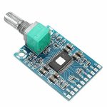
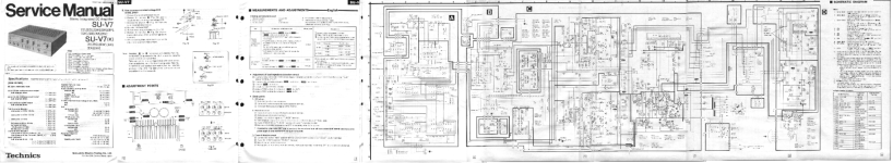
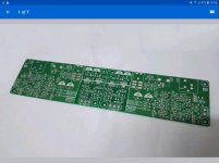
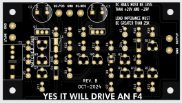
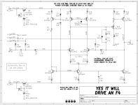
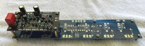
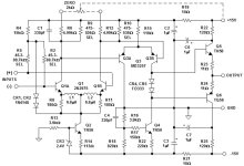
A couple of small tweaks later the newest release (rev B), which I hope is the final release, is presented here in this thread. You can see a top view of its unpopulated PCB, and also the circuit schematic diagram, in the attachments below.

WHAT IS F4 AND WHY DO I MENTION IT HERE?

F4 is one of Nelson Pass's many FirstWatt amplifiers (link). Unusually, the F4's circuitry is arranged as a Unity Gain Buffer: although F4 provides enormous current gain, its voltage gain is only 1X. To get the maximum available output, 20V (peak), you must supply an input of 20V (peak). A large number of DACs, streaming devices, smart phones, and linestages are unable to swing their outputs to 20V (peak), so these are not a good match for the FirstWatt F4.

In fact, it is so rare to encounter a line level device which CAN swing its outputs to 20V (peak), that a snarky catch phrase has arisen here on diyAudio:
  • Yeah, yeah; but can it drive an F4?
I'm pleased to report that the little example circuit presented here, gives an affirmative answer. Yes it can drive an F4. Yes it can swing its output to ±20V (peak).

The board is designed to be installed within an F4 chassis and to use the existing F4 DC rail voltages, with NO modifications of the F4 power supply or the F4 amp channel. Just bolt in the new boards, one per channel, and wire them up. Done.

DOUBLE DECKER / PIGGY BACK MOUNTING OPTION

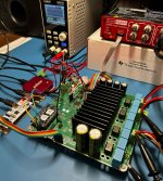
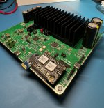
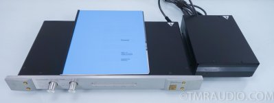
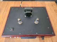
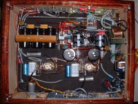
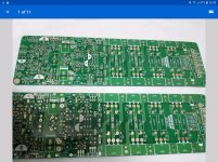
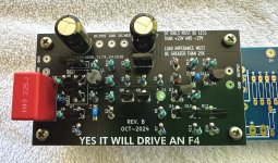
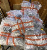
This circuit board is 50mm X 90mm; its mounting holes are 40mm X 80mm. Which is a perfect match to the left hand (or right hand) set of four mounting holes on the F4 PCB: 40mm X 80mm. Using spacers, you can mount it directly atop an existing F4 PCB, in Piggy Back (Double Decker) fashion. Please see the attached photographs.

An F4 amplifier channel board (blue PCB) has a Yes It Can Drive An F4 (black PCB) mounted directly above. The spacers in this picture are 20mm tall (M3 female, hex body, M3 male) but Amazon also sells 25mm tall spacers if you prefer longer. The male ends of the spacers replace the M3 screws which secure the F4 amp channel to its heatsink.

Of course, builders are free to mount their Yes It Can Drive An F4 boards wherever they wish, in whatever orientation they like; there's certainly no requirement to use the piggy back mounting scheme.

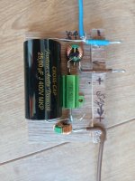
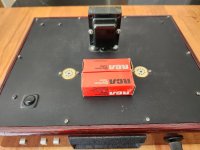
YOU CAN ZIP-TIE Q5 AND Q9 FOR BEST THERMAL CONTACT

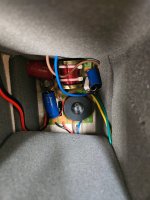
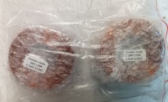
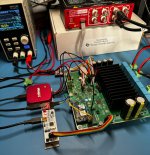
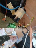
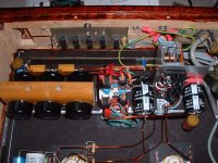
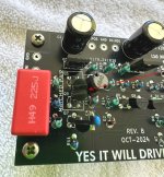
I've arranged the PCB footprints of the matched pair Q5-Q9, so you can zip tie them together (face to face) before stuffing and soldering. Personally, I solder all six legs and then cut off the zip tie, before I scrub the board with 99% isopropyl alcohol to remove flux and grunge. See the attached photo with a thin red arrowhead that points to the matched pair of transistors.

After I'm all finished with IPA and other solvents, then and only then do I apply a dab of heatsink thermal grease between Q5 and Q9. Finally I zip tie them back together again. This time: forever.


CIRCUIT DESIGN OF YES IT CAN DRIVE AN F4

The main goals of this board are (i) to use and to exploit tightly matched BJTs, thanks to the BJT Simple Matcher from BAF 2024; (ii) to provide high gain and wide output swing -- 20V (peak) -- without any shenanigans or funny business on the power supplies. Just use the same ±23V rails as the amp channel, and be able to swing > ±20V on the output.

Goal (i) is met by choosing Q5 and Q9 in the circuit, to be a pair of tightly matched BC546C devices. The schematic asks for matching within plus or minus 0.3 mV; but in the real world you'd just test 30 or 50 NPNs and then select the two pairs with best matching (one pair for the Left channel, one for the Right). If you can't quite get 0.3 millivolt matching, it's not the end of the earth. And if you can get better than 0.3 mV matching, how lovely for you.

Notice that there is only one capacitor in the signal path: input coupler C1, a high quality polypropylene film capacitor by Wurth. C1 blocks any DC offset that may be present on the input ("J6") from polluting the circuit and its output.

The circuit is designed to drive an F4, which includes a pair of AC coupling capacitors between the F4 input buffer and the (large) F4 push-pull output stage. Therefore I have omitted a coupling capacitor at the output of Yes It Can Drive An F4; one is already installed, on the F4 amp-channel PCB. If anyone plans to use Yes It Can Drive An F4 in a completely different application, without an F4 amp-channel, they ought to think very hard about whether or not to AC couple the YICDAF4 output.


CIRCUIT DESIGN: PART 2

Yes It Can Drive An F4 is a two stage amplifier; the first stage is (Q5+Q9) with (Q6+Q8) current mirror load. The second "voltage amplifying" stage is (Q10+Q11) with Q12 constant current load.

Because it's a two stage amplifier taking its output directly from the collector of the 2nd stage, the circuit is not able to drive a low impedance load. But that doesn't matter since the F4 amp channel board is a high impedance load. It's 100K ohms, which is easy to drive, even for this scrawny two stage amplifier.

Bias current for the two amplifying stages is provided by reference current generator Q3, which drives a first current mirror (Q4, Q7) for the first stage, and which also drives a second current mirror (Q4, Q12) for the second stage. The bias current flowing in Q3 is set by zener diode ZD1 and emitter resistor R6:

IcollectorQ3 = Iemitter = (Vzener - VBE) / R6

Plugging in numbers, Icollector of Q3 works out to be approx 2.7 milliamps. Oh by the way, after enduring the tenacious, obstinate, unrelenting "recommendation" of member @6L6, I eventually installed a pilot light LED "D1" in this 2.7mA current path. When power is applied and current is flowing, this LED lights up and reassures you that the circuit board is properly connected to the supplies.

The first stage's bias current is just a resistor ratio multiplication of the reference current

IcollectorQ7 = IcollectorQ4 * (R7 / R11)

In the same exact fashion, the second stage's bias current is another resistor ratio times Ireference

IcollectorQ12 = IcollectorQ4 * (R7 / R20)

It's illuminating to notice that the second stage transistors which drive the output (Q11, Q12), can EACH swing almost all the way to their respective supplies, VTOP and VBOT. Other designs for the second stage constant current source (Q12 here), cannot swing nearly as close to the CCS supply. The current mirror topology is the king of this particular hill.

I have specified the ultra fast and ultra low capacitance diode 1N4151 for position D2. Its part number is exactly 3 greater than the ubiquitous junkbox diode 1N4148, and indeed these two diodes are blood brothers. Diodes whose final eTest measurements are excellent, fall into the 1N4151 bin. And the rest of the diode batch, the average and the mediocre, fall into the 1N4148 bin. I think it's a Good Idea for serious DIYers to have a bag of ten or twenty 1N4151s in their parts cabinet, for those occasions when a super fast or super low capacitance diode, matters. But if you disagree, if you don't want to spend 20 cents on a new diode part number, by all means please feel free to use 1N4148s instead. The circuit's performance will suffer only a very small amount.

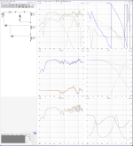
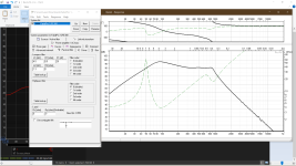
FOR EXPERT DESIGNERS: GAIN-BANDWIDTH, SLEW RATE, AND INDUCTOR L1

Yes It Can Drive An F4 uses an extremely well studied topology with (at first glance) completely standard Pole-Splitting "Miller" compensation. James Solomon's 1974 tutorial article (link) models it quite well; we can populate Solomon's equations by inspection, yielding the circuit's gain bandwidth product and slew rate:

GBWP = { 1/[(1/gmQ5)+R10] } / C5

SR = IcQ7 / C5

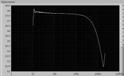
thus GBWP = 9.0E7 radians/sec = 14 MHz

and SR = 100 volts/microsecond.

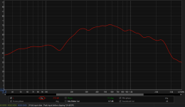
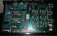
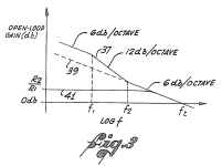
Now let's consider the effect of the inductor L1 in the "tail" region of the Long Tailed Pair, Q5-Q9. This turns out to be quite an old idea; according to Scott Wurcer here on the DIYA Forums, Richard Burwen of Analog Devices used it in 1966(!) on the hybrid discrete opamp "ADI121", shown in the attachments below. Later, Deane Jensen was able to take out a patent (US 4,287,479) on the same circuit. I've snipped out "Figure 3" of Jensen's patent and attached it below.

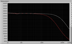
At very low frequencies, the inductor acts like a short circuit, so the emitter degeneration resistors R10,R13 are removed from the circuit at low frequencies. This has two benefits: (i) the noise contributed by R10 and R13 is eliminated at low frequencies; and (ii) the effective transconductance of the long tailed pair stage is greatly increased. In this circuit, gm rises from 2.4 millisiemens to 52 millisiemens -- a growth of 20X (26 dB). There is 26 dB more gain available at low frequencies, thanks to the inductor. That's 26 dB more negative feedback for distortion reduction. And, oh by the way, the Gain-Bandwidth Product increases by this same factor of 20X at low frequencies. It rises from 14 MHz to 280 MHz. Cowabunga.

I encourage expert readers to derive expressions for "f1" and "f2" (the pole frequency and the zero frequency introduced by inductor L1). I think you'll be pleasantly surprised at how high these break frequencies actually are. I think you'll be delighted at how much extra gain / distortion reduction is made available at 20 kilohertz. All for the cost of a single inductor.

DON'T DO ANY OF THE FOLLOWING, THEY ARE BAD IDEAS

First: I have set the gain of Yes It Can Drive An F4 to 20 volts per volt (+26 dB). An input of 1 volt (peak) produces an output of 20 volts (peak), which is the maximum input signal allowed by an F4. Don't attempt to change the gain unless you really know what you're doing. If you need someone to help you change the gain, that means: you don't really know what you're doing. Stop now.

Second: Don't reduce the gain below four volts per volt (4.0X = +12 dB). If you do, there is a very good chance the circuit will oscillate, blowing your tweeters and perhaps also destroying the power transistors on your F4. If you need gain less than 4X, switch to a different design without this limitation.

Third: Don't put this circuit into an amplifier that is wildly different from the standard, stock F4 as documented by Nelson Pass. In particular, don't run at supply rail voltages greater than 29 volts. Neither the transistors nor the capacitors will survive at higher voltage; you will need to design a new circuit with different components and possibly different topology.

Fourth: Don't drive a load impedance less than about 25 Kohms. If you NEED to drive a lower impedance load, you will need a different circuit. This one is designed for the F4 which presents a high impedance load.

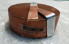
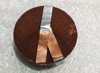
Fifth: Don't experiment with other values of inductance. Either use 680 microhenries (choose an inductor whose self resonance frequency is the highest Mouser will sell you), or else omit the inductor entirely and don't stuff or solder anything into the L1 footprint on the board.

Attachments

  • PCB_top_view_revB.png
    PCB_top_view_revB.png
    211.8 KB · Views: 1,396
  • raster_scan_schematic_revB.png
    raster_scan_schematic_revB.png
    130.8 KB · Views: 1,526
  • stacked_oblique.jpg
    stacked_oblique.jpg
    297.3 KB · Views: 1,844
  • thermally_coupled_BJTs.jpg
    thermally_coupled_BJTs.jpg
    451 KB · Views: 923
  • Jensen_Fig3.png
    Jensen_Fig3.png
    326.9 KB · Views: 947
  • Yes_It_Can_Drive_F4_schematic_revB.pdf
    Yes_It_Can_Drive_F4_schematic_revB.pdf
    33.2 KB · Views: 328
  • PartsList_Yes_ItDrives_F4_revB.zip
    PartsList_Yes_ItDrives_F4_revB.zip
    4.2 KB · Views: 164
  • Gerbers_Yes_itdrives_F4_revB.zip
    Gerbers_Yes_itdrives_F4_revB.zip
    105.5 KB · Views: 161
  • stacked_daughter.jpg
    stacked_daughter.jpg
    462.3 KB · Views: 1,390
  • ADI121_Richard_Burwen_1966_inductors.jpg
    ADI121_Richard_Burwen_1966_inductors.jpg
    94.2 KB · Views: 1,228

When/Where use "low ESR" caps and when/where not?

Hi Folks,


I'm a newbee regarding the picking of certain part types for certain applications. The probably basic questions came up when I read "somewhere", that filter caps right after rectification should not have low ESR:


- In which cases/applications should low ESR caps be used?
- In which cases/applications would "higher ESR" caps be the better choice?
- In which cases/applications it simply "doesn't matter?


Thanks for some enlightment with explanations why.
Regards,
Winfried

What is the voltage and current for Neutron Star clocks 2 and 3

I remember few days ago a member posted the build or their dac with Neutron Star clock (2 or 3, i don't quite remember that) and the power source for the clock was a custom DIY board (one of the power supply boards from DIYA). Does anyone know what is the voltage and current expectations for the Neutron Star clocks?

Thanks.

Marantz CD73 fault

My Marantz cd73 sometimes outputs loud scratchy static sounds usually when first turned on and only briefly. This issue may go away for a week. Then come back again. It may not be there for 20 hours. Then it returns for a short run of torture.

Recapped, new regulators, laser current and focus coil aligned.

Tell me your ideas for this issue ?

Attachments

  • 20250407_171030.jpg
    20250407_171030.jpg
    510.6 KB · Views: 23

For Sale 750 VA High End Toroid Sealed Transformators

For sale: Unique set of two High End 750 Watt toroidal transformers in sealed housing from the German high end brand Thel Audioworld.

Available output voltages are 40, 50 or 60 Volt.
With a 40 Volt configuration the transformer delivers up to 9.4 Ampere, at 50 Volt up to 7.5 Ampere, at 60 Volt up to 6.3 Ampere.

These are unique transformers that are unfortunately no longer available from Thel Audioworld. They served for almost a year in two DIY Pass Aleph 2 monoblocks, but due to marriage and children they had to go to the attic within a year and have not been used for all those years.

These transformers are fantastic for making heavy DIY amplifiers with a superb power supply.

Both transformers have some black spray paint that has leaked onto the transformers through an opening in the housing, but this is of course purely cosmetic.

The new price at the time was (if I remember correctly) around 300 euros per transformer. They can now go for 250 euros both.

Pick up near Arnhem (The Netherlands)but shipping also possible.

Each transformer weighs 6.5 kilos, but I will pack them really well.

Selling can also be arranged by Ebay account.

ESL Diaphragm coating

I have been reading about coatings until I could stand the subject no more. Sigh.

Seems there is very little consensus out there and quite a few secrets :-(

Mind you, I do appreciate the effort that some people put in in finding a good solution for this problem, and I fully understand if they want to keep their secrets. Besides it is their right to do just that. And there is always the risk that some company would want to run off with the formula and patent it. Talk about scr*** the inventor!

So I have absolutely nothing against secrets!

Having said that, I prefer to use a public domain solution (if at all possible). I like the idea of being able to reproduce my efforts at some other time (or by someone else) without the problems of having a supplier going out of business, or being bound by a promise for confidentiality.

Thus the coating is reduced to the following possibilities that I know of:

1) Graphite rubbing
2) Nylon in methanol
3) Glue
4) Elvamide (possible sourcing problem, better to use option 2?)

How are the experiences with any of the above?
Which one seems best for quality and long term stability?
Are there more solutions (pun intended!) for this?

Duplicating a Tangent RS2 (My first DIY)

Objective: Duplicate a vintage Tangent Acoustic RS2 using NOS/Currently available drivers

Intent is to a) first build a copy of the original speaker, and compare it vs the original. If it comes close enough then to experiment with alternate drivers for the 8" woofer, while utilizing the commercially available T27 tweeter.

Equipment on hand:
1) 2x Tangent Acoustic RS2 speakers
2) 2x T27 Tweeters, new from Falcon Acoustics
3) 2x NOS Audax 8" HD20B25J driver (the OEM driver for this speaker)
4) Umik-1
5) Dayton Audio DATS
6) Some free time here and there
7) Lots of enthusiasm

Plan:

1) Cabinet to be built as per the original spec, Of what I understand it's birch plywood with an MDF front baffle. No internal cross bracing, 1-1.5 inch foam padding all around. The drivers are mounted directly to the baffle. Status: In-work, Have opened up one speaker to assess crossover. will be utilized as main reference for measurements.

2) Crossover to be replicated using currently available components. Some interesting findings to share further in the thread.

3) Objective a) Speakers on hand, pending cabinet and crossover. 😀 Easier said than done.

4) Objective b) Have shortlisted 2 drivers (for the forum's review and feedback). File names in ( )

1) OE Audax 8" HD20 B25J specs: (HD20B25H - Catalog 1982)

2) Option #1: Audax HM210C0 (HM210C0 - Catalogue 1994) (comes very close with the fs at 30hz vs the 27 +/- 1 of the OE Audax)

3) Option #2: (slightly smaller) Scanspeak 18W/8424G00 (18w-8424g00)


Other drivers in consideration; Visaton BG20 (sitting by my desk), Visaton W200 (Also sitting here).

Disclaimer: I am not well versed in speaker determination, but I can match numbers better than my kid.

First up, Umik 1 freq response measurements of stock speakers. (1/6th octave smoothing).

RS2 Left speaker.jpg


RS2 Right speaker.jpg


Be right back. Bedtime for kids.

Attachments

Ground connection

Hi everyone,


I’m working on a custom audio build that combines an R2R DAC, an Aleph 1.7 preamp, and a power amplifier inspired by the Dartzeel NHB-108, all inside the same chassis.


Given the mix of digital, analog, and power circuitry, I’m trying to carefully plan the grounding strategy to avoid ground loops and noise. I’ve labeled every GND point in my design and created a PDF diagram showing all connections, supplies, and ground references. Each GND is numbered to make it easier to follow.


🔧 What I’m asking:


I’d really appreciate some help figuring out:

• Which GNDs should be connected together?

• Where should the central ground (star ground) be placed?

• Which GNDs (if any) should be isolated (e.g. digital vs analog)?

• How to properly handle speaker return ground in this context?


The PDF diagram is attached to this post.

Any suggestions or guidance would be hugely appreciated!


Thanks!
Daniele

Attachments

Hoping for some repair guidance

Hi, I know this is a bit of a long shot, but I could use some help on where to start looking for issues so I'm hoping someone may have a guess based on ...very little information.

I have a pioneer d23 active crossover driving 3 way active. A few months ago I replaced all the electrolytics in a successful attempt to repair an issue. I've been using it without issue since then until last night I went to listen to music and got some mild volume from one driver only, everything else silent. After fiddling around a bit I now have no sound from any drivers. It's definitely in the crossover as preamp directly to driver amplifiers works fine.

I'm completely at a loss as to where to start. Powers on fine. I can't see any physical issues. I assume it can't be in any of the individual crossover boards or the whole thing wouldn't just not produce sound at once...

So I know it's not much info but I'm just hoping someone might be able to eat "it's probably xxx" or "check continuity on yyyy" because I'm unskilled and baffled

I Have a copy of the schematic but hifi engine seems to be down for a web version.

There is a version here that requires a few steps...

https://elektrotanya.com/pioneer_d-23.pdf/download.html

Tia for any advice or thoughts

New Markaudio Drivers

Hello all,

As hinted at here and there, Mark has some new drivers on the horizon in the Alpair range.

18 months ago after we successfully released the Pluvia range of drivers, which have been well received, Mark set about the next design evolution. As some of you will know Mark's design ethos is mechanical efficiency, adding lightness and simplifying where possible. In these new drivers Mark has managed to achieve much more with much less.

One of the things that frustrated some of Mark's previous design efforts was the rear suspension being a pain in the ***. The necessity of it leading to design compromise. Freed from the necessity, drivers could be lighter, have tighter production tolerances and could be much more linear through the whole excursion range.

For these new drivers Mark has spent countless engineering hours trying to engineer out this need, not only did he find a solution but it helped him solve another long held desire - greater dispersion. For a long time now the drivers have used Aerospace grade alloys for stiffness, allowing shallower cone profiles. The multiform cone pressing process has allowed Mark to use complex cone profiles to enhance the stiffness further and increase dispersion. The new cones take this concept even further.

The removal of the spider means moving the centre of gravity of the whole drive train so that it can balance without the need for the spider at that centre. Removing the spider allows space for the magnet and the coil/former to move forward which helps, but the cone needed making shallower still. The answer to this answer also answered the question of increased dispersion as well, thus killing two birds with one stone. The new cone is negative camber, so not only is it very shallow but the outside edge actually comes back on itself.

The results of this new engineering leap are presented in the all new Alpair7 MS and big brother Alpair 11 MS where MS stands for Mono Suspension.

I've attached a teaser image here and over the next week or two we will get the PDF's uploaded for mass consumption and Scott will be working up some box designs as usual. the A11MS fits straight into a Frugal Horn XL acoustically although it is a little larger so modification will be needed. The 11 also does work in the Pensil 11 although the alignment isn't quite optimal, Scott is working on either a new design or a way we can all modify an existing cabinet, there will be other designs and obviously the A7MS will get the same treatment.

To start with these will be in VERY short supply but rest assured over time stock will increase and obviously the current drivers will still be available for some time to come as well.

Alpair-11-MS.png
  • Like
Reactions: sser2 and Bryguy

Dipole switching for active speakers (preview)

The weird speaker in the picture below is an updated version of an active 5-way speaker I built about 15 years ago. I wasn't happy with the DSP/amplifiers in the original design, so I stuffed them in a closet until I could finish off new electronics.

Each octagonal "tier" has 8 drivers, and I had wired them so that I could reverse the polarity of the drivers in the back. The original design used relays to reverse the polarity, but in this updated version the polarity is controlled by processing in an ADAU1466 DSP. This approach requires 10 power amps for each speaker, with one amp for the front and one for the back. The DSP processing for the dipole switching/compensation is shown in the SigmaStudio snippet below. Each of the rear drivers has a signal inverter plus a biquad for a shelf filter, plus a gain block to adjust the volume.

I only have one speaker running right now, but I'll get the second one working as soon as we finish refurbishing our upstairs bedroom. I've only got this one speaker running in a small workroom, and there is still a lot of work to adjust the delays and experiment with different crossovers. However, the difference between dipole and monopole mode is fascinating.

I know...the lights are kind of weird, especially when they are flashing to the music 🙂

1744729899708.png


1744729796042.png

Trying to get the best out of cheapo piezos

Over time I've occasionally seen the position advanced that piezo tweeters can be pretty good, but you have to filter them the right way. I haven't heard a fancy pants piezo setup, so I've kinda wondered if it's true. A while back I saw some closeout piezos of the 2x5, 1016 type. They were super cheap, so I ordered 10. They lay dormant in my garage for a time, but now 2 of them will spring forth into a 6" 2-way to sing the song of their people. But can I get it to sound nice?

These will partner with a 6" buyout driver I got some long time ago. It's a buyout that says Taiwan 13014690W. DATS measurement and a modeling says 10L, sealed, f3 ~60 Hz.

So the first thing I did was make up a test baffle and measure all the piezos on it. They start at about 3 kHz, and the biggest bummer I think is the variability 7-10 kHz where there is some sort of resonance. I chose 2 examples that are nominal / matched. All 10 and the selected 2 shown below.

Attachments

  • 10piezos.jpg
    10piezos.jpg
    69.5 KB · Views: 256
  • selected-piezos.jpg
    selected-piezos.jpg
    60.4 KB · Views: 250

For Sale Holco H2-H4-H8

I have several thousand of these old non magnetic Holco resistors.

I originally bought them because I wanted some specific values.

I’m just testing the audience. Is there an interest in me listing those surplus to me? The price will be $1/pcs, min 50 assorted or one type, plain non-registered envelope. $5 in fixed shipping cost.

Of course if someone wants a substantial amount, reduced price and registered shipping will be made available.

Thanks for looking.

R

Attachments

  • IMG_9167.jpeg
    IMG_9167.jpeg
    815.5 KB · Views: 248
  • Like
Reactions: petoluk

Cambridge Audio Azur 840E Schematic, Service Manual

Hi

I am trying to fix my Azur 840E Preamp from Cambridge audio. Some of the resistors are damaged and needs to be replaced. Problem is that they are burnt so bad that the color code is no longer visible.
Therefore I was wondering if anybody on this forum have the scematics or the service manual for this preamp?
Any help is appreciated 🙂

Regards
ohmsweetohm

The Singing Bush Tips 'n' Tricks

The Singing Bush Tips 'n' Tricks, so even Cheerleader Girlie can build it ...

....OK , here it is

ORIGIN THREAD : The Singing Bush


First few posts with graphical info, then I'll write separate posts for both amps, explaining few details


////////

however , most important thing when starting, applicable for both amps:

be sure that trimpot in buffer negative rail (lower JFet group source) is set to max position, prior to first powering up - check that measuring across parallel 39R resistor - reading must be close to 28R

/////////

another thing - remove that silly blue collar from needle wire terminal you got from me - either use heat gun or heat it with solder or lighter ...... then pull it

all wires need to be crimped then soldered in wire terminals, then heatshrinked, to look nice

///////// ( you can see from these slashes that I spent some time recently struggling with Arduino :rofl: )

for 2SK77B - lucky bstrdz having these - all 3W resistors in Mu part of amp - they are still 1R/3W , no change ........... Iq 3A2, output node or SIT Drain (what's easier to reach for measurement) set at approx U/2

///////////

edit 27.07.2020. - SIT Singing Bush startup procedure , post #29

Depletion MosFET Buffer

Here is a little buffer using depletion mode BSP129 SMT MOSFETs.
It will drive low impedance loads at .000% thd range. Frequency response is very extended to video range.
It needs some heatsinking or lots of copper because the current is close to 100 mA.
The circuit is the old White video buffer with silicon.

Attachments

KAC-51 making a humming noise when turned on

I got 4 free Kenwood KAC-51 that do not work. All four have made 2 fets burnt all in the same location.
After replacing the 2 fets and gate resistors I turn it on but only get a loud humming noise. My Oscillator shows a square wave but jumps up and down.
Im hopping if I can fix this one with your help the other 4 will have the same fix or close to it.


Thank

Modifying MidBass Woofer with a cone mounted phase plug?

I have a pair of B&W DM603S3 Speakers. This started as a single tower rescue, and later I purchased a second tower in mint condition for a stereo setup.

One of the things I did was send the midrange driver to a reputable speaker repair shop. The dustcap was torn to shreds. They mounted a CM8 driver phase plug in its place and I never thought about it again.

I am currently modifying the crossovers and that phase plug revealed itself as a major issue I had let go on for years.

The phase plug was mounted to the magnet, which based on research is the correct way to do it. The stock driver has the phase plug glued to the cone and moves along with it . Theoretically the modified phase plug should provide much better dispersion at high frequencies and essentially improve the off axis response. It also explains why my soundstage always sounded phase-ey as they are now essentially completely different drivers.

This woofer has louder high frequencies compared to stock under the same crossover (ear tested without tweeter)

I want to perform measurements to see what else I can find.

Naturally I could just buy a replacement unit, trash this one, and restore parity but curiosity has the better of me and I am seriously contemplating performing the same mod to my stock unit. It would probably require a crossover redesign but I'm already in the middle of that anyways.

I will perform very very rudimentary measurements in the next few days.

Should I call it quits now and just replace the whole thing or is this something worth pursuing?


IMG_20160511_153307.jpg
IMG_20160623_175753.jpg

Bluetooth speaker I brought to Burning Amp 2022

I made this lil bluetooth speaker! I took it to Burning Amp 2022 and a few people were entertained by it, so I figured I'd put up some info about it. Also, it's fairly clearly not fully optimized, so as I continue to work on it ... slowly ... I'll post up results here.

First! Every thread is better with pictures, so here it is.

BT Spkr.jpg


This is what I built based on driver suggestion from Planet10 back in this thread https://www.diyaudio.com/community/threads/driver-choice-for-bt-speaker.385079/#post-6995827 -- if admins wish to combine these threads that's fine. I thought about just continuing with that thread but felt the thread name (Driver choice for BT speaker) was misleading since I've now bought the drivers and am no longer seeking input there.

So what's going on here? This is a pair of MarkAudio CHN-50, in 2 liters per side, each tuned to target 80 Hz. I'm using a Dayton KABD-250 to power them. It's cool b/c it's got bluetooth built in, nice enough little amp, and it's got DSP and uses Sigma Studio which I was excited to try out. It's also got line-in and line-out. There's a battery board that matches it, and you need to get a programmer board to work the DSP angle.

As we played with it at BA, it's got 4th order HP at 80 Hz, and some compression (dual band! yay for Sigma Studio's flexibility) and some EQ. Honestly I don't feel like I've gotten a really complete understanding of the FR yet (I've made a few measurements) so the EQ probably needs honing.

Further, BassBox said that 2 liters would take a port 5" wide and 1/4" tall and 7 1/8 inches long (with a 90 deg turn internal) to tune to 80 Hz. Impedance sweep made it look like I had hit the target, but the guy who was measuring stuff at BA took a nearfield of the driver and said he saw the port null down at 60. So I'll have to verify that and change the porting if necessary, as matching the HP and the tuning frequency to save excursion is a must. Why the discrepency? Maybe the substantial aspect ratio of the port makes it function differently at low level (impedance sweep by DATS) vs higher level (measurement, music playback)? Needs investigation.

Further Mr. Measurement was getting reasonable FR, but REW was giving him odd looking impulse. AND, he came to the conclusion that there was something funny going on, he said he could feel the off cone being driven when feeding a single channel into the measurement (connection over BT), so a few people thought something funny going on with some processing in the BT setup (as distinct from the DSP chip), so I'll have to check that out also.

Finally, if I can get everything else together, the plan is to use flexible tuning options in Sigma Studio to make a sub out with the line-out, that can switch to a higher HP optionally and feed everything else to an external sub.

So that's what's up! I got a job and a family and a house, so probably gonna take some time to go through all this, but I wanted to start a thread while the folks I met at BA maybe still had an idea of the device.
  • Like
Reactions: stv and gregulator

OLD ICEpower 500A Based Amp - Power Up?

I have an Acoustic Reality ear 2 (I think) that probably has not been powered up in 15 years.
It has a pair of B&O IcePower 500A MKII boards that look fine, and a decent sized power supply
with big 10,000uF 100V caps.
I've never worked on a digital amp and am wondering should I power it up on a Variac say
90 to 100V and let the caps form?

Printed on the board is ICE500A MKII

Any suggestions?

Tube audio buffer

I have the following tube audio buffer that I use with my Magnavox AMP-142 which takes a stereo signal, makes it mono and converts it to a lower impedance output as the amp is about 15' away from the preamp and to do it any other way caused extra hum and some Miller capacitance issues due to the first amp stage being 1/2 of a 12AX7.


1743503436083.png


I really don't like running an unbalanced line level signal more than a few feet even if it's a lower impedance due to the potential for hum pickup. I can make the circuit into a balanced output by doing this.


1743505866733.png


The problem is I'm not sure how to convert the balanced output to unbalanced at the amplifier itself without using a transformer.

How would I do that?

Factory Modified Threshold 400A:

Hi everyone, I recently came upon a 400A (dismantled!) which seemed an attractive project for me.
Someone's partially completed amp, which they'd dismantled and done some work on.
When I got it home and began a parts inventory, I noticed this amp has driver boards which don't agree with published 400A schematics
and are labeled “520683 Mod II”.
I've been searching high and low since then for info about the mod, and I did find that Threshold offered upgrades to their older amps to the Stasis technology at some point.
The only other thing I found was a reference saying it could have been upgraded to a S-300.
I tried creating the schematic of the board I have, but that quickly became quite a chore.
I did find tracing the initial input seems to agree with the schematic of the S-300, but there are differences too. (or maybe I'm just interpreting it wrong)
Long story short, this amp is a good candidate for the new Stasis FE, which I'll pursue, but I'd like to play with this first.
I'll post some pics.
IMG_4146.JPG
IMG_4117.JPG

New member

Hi there!

Yes I'm a new member of diyAudio. As many may also quickly find, English is not my native language, but I'll do my best to express myself in English (that is, not copy/paste my threads/responses from Google Translate!).

I'm a retired Linux SysAdmin with experience with Raspberry Pi for 4-5 years now, mainly to build my NAS solution based on OpenMediaVault and many Docker containers.

Now I'm looking for a solution for my audio players with multiroom. I've tried Volumio first, Hifiberry OS (I have 2 Raspberry that have a Hifiberry DAC), a solution based on myMPD and SnapServer, now trying moOde Audio Player.

As every solutions I've tried have there pros and cons, what I look for with moOde is a solution that will evolve without bumps with every update as I have encountered too often.

Alpine X701D-A4 preout issue

Not sure if this is the best area for this thread, but here we go.
My pre-out section on my car stereo recently stopped working. There are three (front, rear, sub)
Rear and sub can be turned off via the software in the menu, but front should be always on. I tested all three to be completely silent. Nothing changed. Everything else works perfectly.
I took it apart for a visual and a few basic probes, but nothing popped out at all.
I am still awaiting a new bench power supply and microscope, so I wasn't able to scope it yet.
Just in case the software got a glitch I did a power drain and factory reset.
Back traced a small bit, there are three opamps then back to a volume control IC, then some traces seem to go back to a dsp chip.
Since Alpine's rep companies in UK won't even acknowledge emails, have no contact number anymore, and Germany didn't answer either, it looks like I'm on my own.
When I do finally get some new tools, I'm gathering ideas on how to proceed. The unit as a whole is pretty complicated and spread between 3 pcb's, but I'm thinking this issue would be contained in this board as the others seem to house the hdmi, usb, and CANBUS interface. The amplifier circuit is working, so I was thinking of tracing both of the paths back to where they meet as, unlike a traditional amplifier, there is no physical input to trace from really. Then taking a signal generator and scope to try and trace it back. I'm still not very adept at following signal path without points a AND b.
Just wondering if you lads had any advice or ideas.
The SMD components go as small as 0402 size and there are many unlabeled larger ones as well which poses an issue. Even the labeled diodes I can't find info on, so it's hard to tell what they should even be reading. At least I can identify the IC's.

Attachments

  • 20250413_162920~2.jpg
    20250413_162920~2.jpg
    500.4 KB · Views: 28

How to build a standalone supertweeter?

Total newbie question, I have never built a speaker. I am planning to build a super tweeter (ST) to sit on top of the bookshelf speakers, a pair of Pioneer SP-BS22-LR . Bunch of questions:
  1. I would need a filter to set the frequency, wouldn't I? I am thinking of setting it at 18000hz, make sense?
  2. Preferably, the ST will take power from the pioneer's blinding posts.
  3. Do the STs have to match the Pioneer's ohm, in this case 6 ohm, and efficiency, 86db?
  4. I am planning to have the ST either face the front wall behind the speakers, or at 45deg angle ear and top, make sense?
  5. How much additional effort to have a level volume control?
  6. What type of driver would be more preferable? bullet? ribbon etc etc? I am open to all.
Thank you guys in advance for helping.

Bad Carver M1.5 Power Transformer?

I am having problems with my Carver M1.5 amp. It acts like the transformer my be bad but I have never had a transformer act like this. With the transformer completely out of the amp,the secondary windings are not hooked to anything and using a Variac on the input widings, I can feed this transformer with 45 volts all day and it will just get warm but push it to 75 volts on the primary and it draws 9 amps on the primary side. At 45 volts in I only get about 75 volts - + on the highest rail. My 1.5T runs 125 volts - + . If this transformer had a shorted winding it would get hot and smoke at any voltage,it does not. It acts like the core saturates at about 50 volts and any more than 50 and you are pushing it hard. Any Ideas?? Many thanks, Al :xeye:

What should the rail voltage be set at on the M1.5 and 1.5t Carver amps?

B&W DM603 S3 Crossover Upgrade Attempt

Inspired by the Rutcho Dm601 S3 mod, I decided to tackle the crossover on my pair of DM603 S3's using his design. It is my first time diving into this and I will admit I have no idea what I am doing. I imported the response graphs of the Kevlar woofer and tweeter into VituixCAD, and simulated the stock and Rutcho crossovers. I came up with a 1.5ohm R1, a 3.3uF C1, short of the resistor on the tweeter inductor. For the mid-woofer, I created a zobel network just like Rutcho, at 4.7uf cap, but a different resistor value of 4.7ohm.

Using a 2.5 Allen key, I removed the silver woofer. There are three screws - one at the middle and one at each bottom corner. The top corners are held by expansion pins. I used a pair of pliers to squeeze them and put my hand behind the board to apply pressure inward. For the zobel, I cut open and balded the blue and brown driver wires and mounted the capacitor and the resistor from the leads vertically. The mounted components are held by glue, and I had to use a knife to pry them off. I did this to both speakers but my beginner soldering skills had my zobel bridge compromised and open. This gave me a unique opportunity to A/B the before and after while running simultaneous modified tweeters.

The highly crossed Kevlar woofer was essentially distorting at the high frequencies. It sounded like outright white noise and heavily muddied the mid-range.
VituixCAD shows on the stock crossover a terrible phase shift after 7.5Khz and both the directivity graphs and phase patterns looked ugly. My post-mod speakers sound huge, delicate, spacious. it is definitely an improvement all around. However, I lost a lot of mid range and I suspect it is due to the 4.7ohm resistor on the zobel. I could play with 1.8ohms but the second problem is that the phase is nearly completely opposed from 2-4.7 kHz. The vocals sound delicate but they are also distant and lacking bark. I suspect I am not getting the full sound stage yet out of these drivers.

After some research, it occurred to me that the zobel increases the order of the filter. For parity, do I have to do the same to the tweeter? I ran this through VItuixCAD and came up with a 4.3uf C1 (I add a 1uf cap in parallel to the existing one), a 4th order filter created by a 5.6uf cap and a 200uh 15AWG inductor, and reducing the Zobel resistor to 3.3ohms.

Attachments

  • Cross_Mod.jpg
    Cross_Mod.jpg
    571.9 KB · Views: 87
  • Cross_Stock.jpg
    Cross_Stock.jpg
    761.5 KB · Views: 71
  • Rutcho_Measurement.jpg
    Rutcho_Measurement.jpg
    301.9 KB · Views: 69
  • DM603fig3.jpg
    DM603fig3.jpg
    42.7 KB · Views: 70
  • DM603_Freq_Response.jpg
    DM603_Freq_Response.jpg
    34.3 KB · Views: 85
  • Rutcho_Based_Mod.png
    Rutcho_Based_Mod.png
    647.2 KB · Views: 80
  • New_4th_Order_Twtr_mod.png
    New_4th_Order_Twtr_mod.png
    667 KB · Views: 83
  • DM603S3 Stock.png
    DM603S3 Stock.png
    679.2 KB · Views: 82
  • Like
Reactions: zaylle44

Jantzen Audio coil inductors

For sale are Jantzen Audio coil inductors:

000-1299 Air Core Coil 2,200mH +/-3% 0,630Ω wire 1,20mm=17AWG OD-57 / 30mm 10€/PCS

000-6542 C-Coil 13,3mH +/-5% 0,25Ω +/-10% 500W / 8Ω wire 1,2mm=17AWG core-40 OD87 H28 32€/PCS

000-8450 Wax Coil 3,300mH +/-2% 0,51Ω +/-5% 14AWG OD106 H37 52€/PCS

Coils are unused

Shipping from Slovenia, EU

Attachments

  • IMG_20240606_085154.jpg
    IMG_20240606_085154.jpg
    214.3 KB · Views: 65
  • IMG_20240606_085157.jpg
    IMG_20240606_085157.jpg
    316.8 KB · Views: 71
  • IMG_20240606_085223.jpg
    IMG_20240606_085223.jpg
    323.3 KB · Views: 66
  • IMG_20240606_085239.jpg
    IMG_20240606_085239.jpg
    234.6 KB · Views: 69

Two XH-M564 class d amplifier as one amplifier

Hi I'm new here forgive any mistakes. I want to use two XH-M564 Modules as one amplifier so i can get 200 watt output as 2 channels If possible. Or 4 channels output. This module contains tpa3116 d2 amplifier chip and it is a stereo module gives 50w per channel output

Attachments

Sony Esprit TA-E901 - Any Service Experience on Phono?

I have a Sony Esprit TA-E901 Esprit pre-amp. It's a bit of a unique beast.

On the phono stage only (all other inputs are fine), I have an intermittent right channel problem in stereo. Especially when warm, the right channel will go dead. Sometimes it will work for days at a time before not working for days at a time. All other inputs will still work perfectly when the phono stage is acting up.

I took it to a known good electronics shop, and they were baffled on what was wrong. They couldn't find anything. They successfully reproduced the right channel issue only on the phono stage.

My question is because the problem wasn't obvious, do you think one of the epoxy modules in the EQ or Flat Amp? Or something that takes more diligence like finding a cold solder or something given the complexity of the unit.

My Garmin Nuvi with Euromaps gave out -- anyone recommend a new one?

My Garmin Nuvi GPS, the one with European maps, isn't taking a charge. While I can use Google or Apple Maps on the iPhone I've found out that you can wind up on a C-Road in France behind some fella's harvesting. Moreover, when we went to Ireland the cell service was spotty and we had to drive until it became operational again.

Garmin no longer makes an automobile version with Euro maps. Even they suggested buying one in Europe.

NAD 7250PE help with finding short

Hi, I have this amp that is blowing the fusible resistor R632 in this Left Channel Amp Circuit. I've tried to isolate different parts of the circuit and have all of the driver transistors Q616, 617, 618, 619. 703, 707 as well as Q609 and all of the complimentary right channel transistors unsoldered and out of circuit and the resistor still blows after some time. When the resistor is out, I measure -70v on one side and like 2v on the other. When I remove right channel's complimentary resistor 682l, I still get -70v but on the other side where on the left I get 2v, on the right I get around 7v. Just looking for some guidance on how to hunt down what's causing this. I have read the variable resistors on this board can cause fits but not sure how to identify if that's the problem here...

1742311380220.png

Need help designing my first amp :D

Hi everybody! I'm a newbie seeking to design my own amplifier. I would be delighted if someone from this hobby could guide me along. Let me try to explain the features and what was intended.

1. I'm designing a stereo amplifier for Headphones/IEMs.
2. I use 1x NE5532 for each channel for a HPF (15Hz - 23kHZ) -> LPF + HPF = HBF
3. I then used 1x LME49720 for each channel for the unity buffer stage + "power" amplification stage.
4. Each op-amp ICs are connected to 100nF & 1uF capacitors for both power rails as decoupling capacitors.
5. I'm using 3.5mm TRS for now, but I'm considering a 4.4 TRRS Balanced connection as well. Maybe both?
6. This is a derivative from the "47-amp", but I'm thinking of making it into a portable amplifier...
7. I understand that L48xx/L49xx voltage regulator ICs is common, but it seem to be far too noisy as the power supply for audio applications and will need further circuit additions to be usable. Is there any recommendations for ICs replacement? With portable in mind, OOTB regulator ICs would be preferred?
8. I intend to do op-amp rolling [the LME49720s] so my first prototype would be DIP8 package for now on a breadboard. If it works, I will move on to PCB design using SOIC chips, the passive components shall be surface mount as well.
9. I will be separating the ground into signal ground (which is use AGND here) and true ground (GND)

Any feedback is welcomed 😀 2 random question out of this project:

1. Does it makes sense to replace the unity-buffer stage with JFET transistor amp design? I heard it makes the amp slightly colored to be more warm... in fact if I could implement both and choose between JFET (Warm) and Op-amp (Sterile) in one circuit would be fantastic!!

2. Am I the only one that thinks the commercial "portable amplifiers" are much larger than needed?
1744351503787.png

Does relationship between single resistor attenuation linear?

Assume a 6.8 Ohms resistor is placed in midrange crossover at the input terminal side and a 2 Ohms resistor is placed at the same position in the tweeter crossover. The difference between them is 4.8 Ohms (6.8-2 Ohms). If the woofer is replaced with a higher sensitivity one, the mid and tweet will need to lower their attenuations. And if the tweeter is bypassed its 2 Ohms resistor, would it be successful by simply replaced the 6.8 Ohms resistor of the midrange by a 4.8 Ohms resistor? By doing this, the difference between tweeter's and mid’s resistors still remain 4.8 Ohms (4.8-0 Ohms). That means the relationship between these two resistors is linear. Is this assumption true?

How to upgrade your 1st Gen Klipsch Jubilees to 2nd Gen (Heritage) Jubilee Acoustic Performance

This is aimed solely at those owners and potential future owners of first-generation Klipsch Jubilees that want to upgrade them to meet and/or exceed the acoustic performance of second-generation Jubilees (pdf attached).

EDIT (31 July 2024): Those owners of 2nd-Gen (Heritage) Jubilees can also access assistance here in getting those loudspeakers dialed into their listening room environment. There is a real need to do this with virtually all home-sized listening rooms, as the fixed factory settings in the Heritage Jubilee DSP crossover will likely be overwhelmingly imbalanced below 40 Hz. I've also found that "room correction software" packages like Dirac and Audacity have systemic issues in the room transition region (a.k.a., Schroeder transition region) that seems to consistently produce unbalanced results for these type of loudspeakers.

EDIT (27 April 2025): I now have a Xilica XP or XD series processor configuration file, otherwise known as an *.xdat file, that has the necessary PEQ, crossover filters, and channel delay corrections to dial in a stereo pair of Heritage Jubilee with Axi2050 drivers - also known as K-694 drivers.

Send me a message if you have interest in changing your fixed Klipsch DSP box with another third party DSP processor or PC-based DSP solution (e.g., CamillaDSP, etc.). The settings in this configuration file use something known as a "zeroth order" crossover, which has no all-pass phase growth due to the crossover filters themselves. This allows the user to possibly avoid using FIR filtering to further flatten the phase response of Heritage Jubilees.


Chris

Attachments

Technics SU-V7 bias problem

Hello,

Had this one in my office for a while. I did a full recapping job, calibrated most of the things, per service manual, then ran into a bias problem and left it there.
6 months after picking it up where I stopped.

What I did:
  1. all electrolytic capacitors changed​
  2. both Thyristor replaced (were damaged)​
  3. Supply voltage adjustment & check done and working
  4. Adjustment of load impedance detection circuit done and working
  5. DC balance calibrated and working
  6. Protection circuit calibrated and working
  7. Overload detection circuit calibrated and working
  8. replaced output relay
  9. cleaned controls and potentiometers

The problem, adjustment of Ico (bias).
The right channel is nicely biased @ 2mV, as the manual suggests. Everything works smoothly with it.
The left channel, oh boy oh boy... Looking at the schematic, my Q317 collector measures 0.5V, Q319 collector measures -3.3V, with respect to 0V. Everything after that is not even close to the values in service manual...
My thought, I have one channel working, and I don't have these transistors in stock, let's change transistors and diodes from one channel to the other and see.
I exchanged (left channel with right channel): Q317, Q319, D305, D307, D311, D309, Q321, Q331, Q333, Q327, Q329. Of course, I didn't replace everything just like that.
I check the bias adjustment after each exchange. The thing is the same... I also checked resistors, all good. I resoldered most of the left channel. Still the same. I measured all ceramic capacitors on the left channel, all good.

The amplifier works, it passed the signal, but after few watts of power, as expected, the left channel waveform (the bottom sine wave) starts to distort.

Any ideas? Any help will be appreciated. Maybe I'm missing something, or everything 😀

Ciao,
John

EDIT: VR301 is also replaced with new trimmer, Z301 power resistor has been replaced also. Schematic is attached, so you don't have to search through manual 😉 The voltages before bias circuit (Q301, Q303, Q309, Q313, Q315, Q311) are correct.

Attachments

  • Technics_SU-V7-schematic.png
    Technics_SU-V7-schematic.png
    721 KB · Views: 50

6SN7 + EL34 SE stereo amplifier build - questions

Hi folks, I have a stainless chassis, some Chinese iron, and some Russian and Chinese tubes that I'd like to turn into a decent amplifier. The schematic that comes with these kits varies widely, and the one that came with this kit is a mess. It is attached. It shows the two halves of the 6H8C/6SN7 drivers wired in parallel, which I have been told is generally a bad idea and also not necessary. So my idea is to simplify and just use one half of a single 6H8C/6SN7 driver tube for each channel.

I also got rid of the tube rectification in the power supply discussion here: https://www.diyaudio.com/community/threads/5c4s-replacement-with-solid-state.405726/

I am at the point where I am trying to put together a schematic that will not just work but work well in case I decide to keep this amplifier. It started out as a learning tool and an experiment where I didn't care much about the final result, but now that I am this deep into it, I'd like to do at least a half way decent job.

I have redrawn the schematic to show the solid state power supply and 1/2 6H8C/6SN7 per channel.
  • I have no idea how to determine the proper values for the negative feedback resistor and any parallel NFB capacitor. I'd like to move the negative feedback to the 4 ohm output. I will not ever use the 8 ohm outputs, and although I know in theory it should be fine to attach the negative feedback to the 8 ohm output anyway, to satisfy my curiosity I'd like to put it on the 4 ohm output.
  • Is there any reason for me to try 4k (or higher) output transformers instead of the 3.5k specified? I'll be replacing the tiny ones that came in my version of this kit and I can get any value needed - update 3/30/2025 - larger replacements arrived today.
So if this group can help me optimize this schematic, at least getting it close enough for me to build it and test voltages and see how it sounds, help would be very much appreciated. I will be replacing all of the resistors and caps that come in the kit with decent parts from Mouser and Digikey. I will get whatever is needed to do it right. update 3/30/2025 - adding parts to Mouser and DigiKey carts. Proposed schematic with regulated screen supply and a single driver tube attached.

I do not have an oscilloscope. I thought about buying one of these but I would have exactly no idea how to use it or how to begin. https://www.amazon.com/Hantek-Digital-Storage-Oscilloscope-Analyzer/dp/B015XVPPJ6

Proposed schematic updated 3/30/2025:

schematic SEP 6SL7-EL34 regulated.jpg

Attachments

QUAD 33 Balance Problem

Hi - I have a Quad 33 where the balance is doing strange things. Symptoms;
  • With the Balance slide centered - The Right Channel is much brighter in the mid and treble, the left by comparison is dull
  • With the Balance slide fully to the Right - The right level increases by about 70%, the left level decreases by about 20%, and remains dull
  • With the Balance slide fully to the Left - The the left level increases by about 50-60% and the sound is not dull, the right level decreases by about 10-15%, and sound is dull
I have carried out the tests above with the Controls(Bass, treble & slope) in "Cancel" mode

1744549758147.png


I have checked RV5. The mechanical linkage is sound, the resistance of the pot is circa 1K Ohms, and in center setting about 500 Ohms either side. This grounding of the center of the pot is good as well.

I have swapped around the M12017 boards, left to right to confirm there is nothing wrong with either of them.

Should I be looking a be looking at potential issues around here?
1744550052586.png
.
1744550072601.png


Any help or insight would be appreciated.
Projects by fanatics, for fanatics
Get answers and advice for everyone wanting to learn the art of audio.
Join the Community
507,773
Members
7,888,047
Messages

Filter

Forum Statistics

Threads
406,219
Messages
7,888,047
Members
507,773
Latest member
pete2000