I have the following tube audio buffer that I use with my Magnavox AMP-142 which takes a stereo signal, makes it mono and converts it to a lower impedance output as the amp is about 15' away from the preamp and to do it any other way caused extra hum and some Miller capacitance issues due to the first amp stage being 1/2 of a 12AX7.

I really don't like running an unbalanced line level signal more than a few feet even if it's a lower impedance due to the potential for hum pickup. I can make the circuit into a balanced output by doing this.

The problem is I'm not sure how to convert the balanced output to unbalanced at the amplifier itself without using a transformer.
How would I do that?
I really don't like running an unbalanced line level signal more than a few feet even if it's a lower impedance due to the potential for hum pickup. I can make the circuit into a balanced output by doing this.
The problem is I'm not sure how to convert the balanced output to unbalanced at the amplifier itself without using a transformer.
How would I do that?
Typically you would use either a differential amplifier (LTP) or a Broskie CF. Or indeed both, as he describes here:
https://www.tubecad.com/2011/03/blog0203.htm
https://www.tubecad.com/2011/03/blog0203.htm
Have you tried simply lowering the AMP-142 input resistor to 47K or even less from 470K? I do that with my amps because I drive them only with SS pre and all is quiet and fine over 20ft. standard good shielded RCA lines of reasonable cost/quality. My amps, Maggies and DIY typically have 12AX7 type inputs.
Last edited:
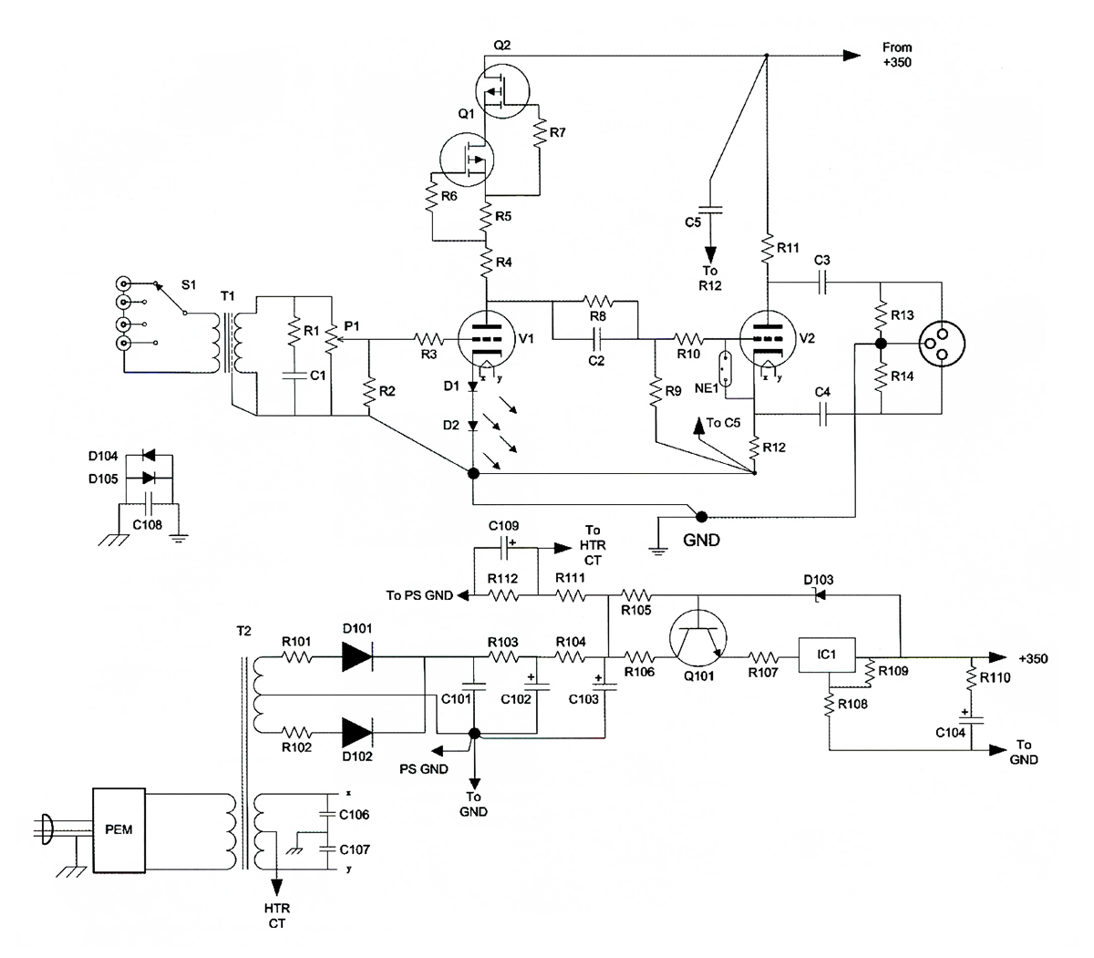
I don't have the whole amp schematic of the amp handy, but I do have the part where I redid the input and phase splitter.

I sort of figured it wouldn't be that simple to convert the balanced to unbalanced without using tubes. I could use an Edcor WSM15K/15K balanced/unbalanced to balanced/unbalanced transformer, but I don't know if it would negatively affect the sound.
I sort of figured it wouldn't be that simple to convert the balanced to unbalanced without using tubes. I could use an Edcor WSM15K/15K balanced/unbalanced to balanced/unbalanced transformer, but I don't know if it would negatively affect the sound.
In your split-load circuit, if the plate cap side is grounded at, say, pin 3 of XLR connector, the circuit becomes an unbalanced cathode follower. Your circuit has inverted polarity by the way.The problem is I'm not sure how to convert the balanced output to unbalanced at the amplifier itself without using a transformer. How would I do that?
Have a look at Stuart Yaniger's Impasse preamp article that shows the circuit below.

If the amp didn't have feedback I could wire up the 12AX7 stages as voltage amps and feed a balanced signal directly to the amp.
The amp uses an output transformer with 4 8 and 16 ohm taps.
If I just have to go with a balanced signal, how would I modify the amp to where it can still have feedback?
Before I do anything I may take an Edcor WSM6400 stereo to mono balanced transformer home from work then connect it to an Edcor WSM15K/15K balanced/unbalanced to balanced/unbalanced transformer with its output feeding the amp and see how it sounds. If there's no noticeable impact to the sound quality then I might order one of those Edcor WSM6400 stereo to mono balanced transformers and use that.
If the transformers work it would eliminate the need for the tube audio buffer.
One reason for doing this is I have a slight hum and I'm not sure if it's coming from the amp itself or the audio cable to the amp or the buffer circuit.
Your high input impedance is going to make it sensitive to environmental radiations. Do you get hum with chassis grounded inputs? Open inputs? Grounded cables on the open end, no pre or source, when attached to the amp?

You can ground 4 ohm tap as the center tap and take feedback from 16 ohm and Common symmetrically feed back to 12AX7 cathodes.The amp uses an output transformer with 4 8 and 16 ohm taps.
If I just have to go with a balanced signal, how would I modify the amp to where it can still have feedback?
That's the stock schematic, however mine is not totally stock. Think I do have the correct schematic at home though. Will post it when I get home from work.
The hum is barely audible with my ear right close to the speaker. Now if I unplug the input to the amp I get some buzz which is to be expected. I can solve that by wiring the switched portion of the jack to ground.
I can ground the input and see if I get hum.
Not quite sure what the output impedance of the buffer is, but it is low enough to eliminate a miller capacitance issue I had when I used two 5k resistors on the input to sum the stereo to mono before I built the buffer.
With the 10uF cap on the output of the buffer I can use a 47k resistor to ground on the amp input and still have zero phase shift at 20Hz.
I don't know if it's the speakers I use with tube amps having a higher sensitivity or maybe I just hear real good, but I can hear hum in a speaker with my ear close to the speaker even if the voltage across the speaker is just a few millivolts.
I did not know that.
Gonna try other solutions first and only modify the amp as a last resort as it took much testing and work to get the amp to be basically flat to 20kHz.
The hum is barely audible with my ear right close to the speaker. Now if I unplug the input to the amp I get some buzz which is to be expected. I can solve that by wiring the switched portion of the jack to ground.
I can ground the input and see if I get hum.
Not quite sure what the output impedance of the buffer is, but it is low enough to eliminate a miller capacitance issue I had when I used two 5k resistors on the input to sum the stereo to mono before I built the buffer.
With the 10uF cap on the output of the buffer I can use a 47k resistor to ground on the amp input and still have zero phase shift at 20Hz.
I don't know if it's the speakers I use with tube amps having a higher sensitivity or maybe I just hear real good, but I can hear hum in a speaker with my ear close to the speaker even if the voltage across the speaker is just a few millivolts.
You can ground 4 ohm tap as the center tap and take feedback from 16 ohm and Common symmetrically feed back to 12AX7 cathodes.
I did not know that.
Gonna try other solutions first and only modify the amp as a last resort as it took much testing and work to get the amp to be basically flat to 20kHz.
Last edited:
Some mention needs to be made as to the quality of the long interconnect cable- is it a decent cable? Yes- ground the center to shield at the end of the long cable farthest from your amp, and see if you still hear any hum.
The cable is quality. The first cable is a 6' GE brand RCA cable I bought a few years back from Wal-Mart, however I had the need to cut one in half once and the cable is well made with good shielding. The other cable is a 6' Radio Shack 1/4" male to RCA female cable.
Yes- I echo what 20to20 said- the grid resistor at the input of your amp is really high to begin with- 470K. This was because typically the output source impedance of the Magnavox radio chassis was really high, but also connected via very short cable. You have exacerbated this problem by changing 470K to 1M so a flea farting will induce noise. On all of my Magnavox chassis, I add a 10K volume pot to the input so I can listen to directly connected CD player. 10K is very easy for modern sources to drive (which typically have output impedances below 1K). When I am using a preamp with volume control, I turn this pot all the way up, but it still places a 10K resistance from input to ground and does a great job of eliminating hum. Are you using a tube pre-amp? If you are, it may also have high output impedance, and you will have to do all of these gymnastics to preserve such a high impedance signal. But, if you are only using modern solid state sources, make your life easier and add a pot or resistor before the .68uF cap.
I tend to be of the camp that everything that touches the audio path degrades the quality, so less is more. By adding a bunch of even well designed buffer and conversion stages before and after the long run, you are adding noise, distortion, and more headaches than you are fixing.
I am using the audio buffer I posted in the first post.
The 1 meg is there due to the different phase inverter circuit I used which eliminates the issue of needing a 12AX7 needing matched sections and also eliminated an issue I had of the upper audio frequency response not being very good.
Thought I had an updated schematic showing the modified fixed bias circuit, but somehow that mod slipped through the cracks as I am usually very good about updating a schematic when I change some part of the circuit in an electronic device. I should have a schematic done tonight.
I wound up using the power transformer from a Bogen CHS-35A amp to provide the bias voltage.
Last edited:
You can leave the whole phase inverter and 1 Meg alone. Put a 10K to ground at the input connector (or a pot) and you're done. Toss the audio buffer.
I ask again- Are you using modern solid state source, or a tube source to drive your buffer and long run?
I ask again- Are you using modern solid state source, or a tube source to drive your buffer and long run?
The hum is barely audible with my ear right close to the speaker.
Honestly, that's power supply filtering or microphonics from PT vibration or output tube idle balance. Grounding the inputs should show if it's the amp. Good luck trying to get 100% silence. It's doable but I think you need to try other possibilities before focusing on the input type. It doesn't sound like a ground path issue. It sounds pretty common and most folks would let it pass as you describe it. I've squeezed low hum out of an amp and it takes some patience if filtering doesn't do it on the first attack. But if that's a secondary issue, and noise from a longer RCA cable is the 1st issue, I think it's the high input Z. Use some clip leads and jumper in some different grid to ground values. It could be that simple. Lower input Z should kill the affect of Miller and cable capacitance.
Last edited:
I've squeezed low hum out of an amp and it takes some patience if filtering doesn't do it on the first attack.
I saw in a Philco 118 cathedral radio where a capacitor was put across the choke to resonate the choke at 120Hz and that greatly reduced the ripple voltage. I tried that once in a tube amp I built and it dropped the ripple from about 200mV to 12mV and the barely audible hum in the speaker attached to it was gone.
I did that to this amp a few months ago and the B+ ripple after the choke is 27mV.
I shorted the input to ground and only hear a barely audible hum with my ear right at the speaker which sounds more like a 60Hz hum. For some reason I connected the junction of the two 100 ohm resistors that are across the heater winding to the - bias voltage. Maybe that's causing the residual 60Hz hum. Only other thing I can think of is inductive coupling, however the cores of the power transformer, bias power transformer and output transformer (I used an Edcor) are all at right angles to each other so that cannot be it as I'd hear the hum in the speaker before the tubes warm up.
I connected the cable, disconnected it from the buffer and shorted the signal and ground to each other. So the hum may be coming from the buffer.
Toss the audio buffer.
I need it for gain. When I redid the input and phase splitter the gain was reduced some plus my preamp has a gain of 1 in passive mode and active mode with active mode using a FET.
So I might try the transformer idea and ditch the buffer as I got the buffer as hum free as I reasonably could, however it must not have been enough.
Well, that is a good technique to reduce hum. With the cathode at a positive voltage so the grid is negative, the cathode can act like a plate, drawing AC electrons from the hot filament wire and inducing filament hum right into your cathode. Dave Gillespie did this on his 8600 build for that reason.For some reason I connected the junction of the two 100 ohm resistors that are across the heater winding to the - bias voltage.
Everything in engineering is a trade-off. Pick your monkeys. I prefer minimalist elegance.I need it for gain.
The ripple voltage on the - bias voltage is 100mV. Now if the output tubes were much better matched that ripple would not be a problem, however the tubes are not 100% perfectly matched so maybe that's causing the barely audible 60Hz hum as the bias supply uses a 1/2 wave rectifier. I used a 56uF 125V cap so I can either make a bridge rectifier or increase the cap size.
- Home
- Amplifiers
- Tubes / Valves
- Tube audio buffer