

I think, but someone will correct me if I am wrong...
You have a 3-way modelled. A 2.5 way would have no high-pass on the midrange. If it were passive, the woofer would just have an extra inductor, so try But06 rather than But12 on the woofer.
You have a 3-way modelled. A 2.5 way would have no high-pass on the midrange. If it were passive, the woofer would just have an extra inductor, so try But06 rather than But12 on the woofer.

Considering I don't know what I'm doing it's possible. This is midrange high pass shorted and a But06 on the woofer. Is this what it's supposed to look like?

The ".5" in a 2.5/3.5 way is usually used to counteract baffle step loss. You can simulate baffle influence in vituixcad.
It seems you use ideal drivers in 2pi configuration (thus no baffle step) in your simulations.
Edit: full 6dB baffle step compensation by adding a second driver may be too much for many cases, by the way.
It seems you use ideal drivers in 2pi configuration (thus no baffle step) in your simulations.
Edit: full 6dB baffle step compensation by adding a second driver may be too much for many cases, by the way.
Last edited:
I may be wrong cause I don't know what I'm doing as well, but in theory should be something like that: adjust filter type/slope and level of the drivers as you like.Considering I don't know what I'm doing it's possible. This is midrange high pass shorted and a But06 on the woofer. Is this what it's supposed to look like?
Try this. (I'm a rookie at 2.5x-overs.) Playing around in PCD, this seems to work.
Adjust the .5 woofer to be 3dB lower than the main woofer, and cross it 2nd order at 350hz. No additional filtering on this woofer, other than EQ or notches, if needed.
Now roll off the main woofer as needed to blend with the tweeter. .
Adjust the .5 woofer to be 3dB lower than the main woofer, and cross it 2nd order at 350hz. No additional filtering on this woofer, other than EQ or notches, if needed.
Now roll off the main woofer as needed to blend with the tweeter. .
Last edited:
I think, but someone will correct me if I am wrong...
You have a 3-way modelled. A 2.5 way would have no high-pass on the midrange. If it were passive, the woofer would just have an extra inductor, so try But06 rather than But12 on the woofer.
That's correct. Also, because they have different outputs the woofer and "mid" can't share the acoustic space, so common to see the "mid" in a sealed compartment and "woofer" in bass-reflex.
My suggestion is to steepen the woofer's low pass filter, and lower it. It looks like you are trying to get some midrange output from it, and htat's not really the point, and as you can see is mucking with your off axis plots.
Theoretical simulations with ideal drivers are a great way to check the viability of your basic design or to test some unusual topology, I'm doing them a lot. Great study tool too.
You don't need to flatten drivers' responses with a transfer fuction tool, that's a task for crossover to do.
6in + 1in is inherently a bad topology, the directivity mismatch is simply unavoidable. Any loudspeaker is a compromise, but here the compromise is greater than usual. Do you want to improve your existing speaker, or to build one from scratch? Basically, how fixed are you in the driver choice and baffle layout?

I have tried to achieve smoother horizontal directivity at mid/tweet x-over by using asymmetrical slopes and moved x-over higher in frequency for better verticals (and to avoid edge diffraction). Maybe even higher x-over point would be better.

Lowest driver compensates baffle step.
You don't need to flatten drivers' responses with a transfer fuction tool, that's a task for crossover to do.
6in + 1in is inherently a bad topology, the directivity mismatch is simply unavoidable. Any loudspeaker is a compromise, but here the compromise is greater than usual. Do you want to improve your existing speaker, or to build one from scratch? Basically, how fixed are you in the driver choice and baffle layout?
I have tried to achieve smoother horizontal directivity at mid/tweet x-over by using asymmetrical slopes and moved x-over higher in frequency for better verticals (and to avoid edge diffraction). Maybe even higher x-over point would be better.
Lowest driver compensates baffle step.
@VoxCelestial "Do you want to improve your existing speaker, or to build one from scratch? Basically, how fixed are you in the driver choice and baffle layout?"
I chose the size because a Scan-Speak 15W8424 was one of the suggestions on the 3-way budget monkey box build thread and SS supplies CAD files I can use to measure diaphragm diameters. In this case, 120mm. So it was the 3D file that drove the decision.
I have no idea what size drivers work well with 2.5ways + 1 inch domes. Revel has a F35 and F36 with 5.25in and 6.5in diameter drivers but I don't know what that means in terms of diaphragm diameter.
I'm not at all fixed on baffle layout. I'm just trying to get an idea of how these are designed and what advantages they create. With the 1 inch dome I would most likely use a waveguide and enclosure simulation (shaped to assist directivity) in a real build.
Basically anything up to about 10 inches - as long as tweeter is paired with equal waveguide, like in Revels. Without a waveguide there won't be an adequate directivity matching. So, to get smooth dispersion w/o WG, it's better to switch to something like 10+3..4+1 in, which will get you smooth power response and early reflections. Moreover, instead of traditional vertical arrangement it's beneficial to do something a-la KH310, but with a low W to M crossover - this provides some directivity control down to Schroeder, at least in horizontal plane. Constant wide directivity from 400 Hz to 8 kHz:I have no idea what size drivers work well with 2.5ways + 1 inch domes
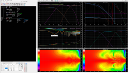
Anyway, I explored the 6+1 layout further. First, I've moved M-T crossover even higher and changed slopes to asymmetrical 3rd order Butterwort/Bessel. This finally gave me truly smooth power response and early reflections, although the vertical directivity isn't great. It's an inevitable compromise when stepping from large mid to 1" tweeter; besides, Infinity Primus series used similar trick and was highly regarded, so verticals appear to be an acceptable sacrifice, if nothing else could be done. Second, instead of MMT layout I switched to MTM layout, as it gives larger acoustic source size and, therefore, directivity control to lower frequency.
This concept can be refined further by adding another 6 in driver and switching to 3 way topology (I don't like .5 way that much). This gives us very constant 5-6 dB directivity index from 400 Hz to 10 kHz (take note at how 1000-400 Hz HOR widening is compensated by VER narrowing in the same range) and reduces IM distortion, as midrange cone now barely moves at all.
Finally, we move that third driver to the very bottom. Though vertical directivity at low mid now looks a bit wonky, this increases source size at low frequencies even more, increasing DI and, more importantly, reducing floor bounce and associated peaks/dips in the lower midrange (compare tangerine/dashed blue floor reflection curves), so in real rooms this layout will sound better.
Attachments
Last edited:
@VoxCelestial
It's amazing how vituixCAD simulation can let you explore a complex design like that. It also gives me a chance to see the details in your crossovers and see what it changes in the graphs. It looks like you designed a 3.5 way if that's the correct terminology. And I can see the crossover order choices as well as the frequencies where they are applied. Just because I don't know anything so I'd always cross one typology with the same, except you created unmatched typologies and it worked well from what I can see. That's pretty advanced from my point of view.
The ScanSpeak 15W8424 has low frequency limitations. It can only make it down to 200Hz with just one but could probably make it to 150Hz with two or three of them. So ultimately it's the wrong driver choice for something like this. It can never be the 2.5 Revel or 3.5 way you designed here.
1) Would you ever build the 3.5 way you designed here (but using different divers)? Is it a design that shows promise or is it just making the best of my bad starting point? If it does have merit in your opinion, what drivers would you choose for it?
2) What designs would you pick for a ScanSpeak 15W8424? After all this, I'm sort of confused what ScanSpeak intended for the driver. What purpose did they design it for?
- Home
- Loudspeakers
- Multi-Way
- 2.5 Way Crossover Simulation Help