For Sale Singxer SU-1 USB Bridge

I am continuing to clear the cupboards, and this time it's the Singxer that is up for sale.
Never really used the thing. I got it in 2020 pretty much new, and it was since then in the box, never used.

So in great condition, looks like new and in the original box. pictures can be provided in MP.

Selling for 175 EUR. Shipping in EU prefer, but will ship internationally (that of course risks to cost a lot...).

For Sale DIY Audio PC components clearing

We will be doing large renovation works in our house, and I am looking to clear out a lot of components I accumulated over the past 4 years from different projects. Shipping in principal in EU, but happy to discuss oversees shipping especially if purchasing multiple items. Photos and details in MP

WaveIO XMOS-based Asynchronous USB to I2S interface - card only - 20 euros - RESERVED

Multiple components intended for an audio PC project that never happened.....

Streacom FC10 Alpha case. This was a complete audio PC I bought a few years back. I have kept only the external case (and the base mobo unit inside - see below) - 50 EUR - I also have the original box so can be shipped securely.
Multiple Streacom FC10 accessories I sourced from Streacom to complete the nude case and allow the installation of a fresh Audio PC:

New in the box Heat pipes - SH2/LH4 - 30 EUR
New in the box HT4 Thermal Riser - 10 EUR
Additional screws and bits and pieces required to complete the box - free for the buyer of the other items
New in the box HDplex 400W Hifi DC-ATX - 60 EUR
Motherboard Jetway JNF9M including 8GB of RAM - Pentium N2900 - low power and ideal of a streaming end point. Currently installed inside the case - prefer to sell together - 30 EUR

VOX AC30 CC2 Ground scheme

hey team,

Just fixing up a Vox AC30CC2 and for the life of me I can't figure out what the purpose of the ground scheme is. All the grounds come to a common point via the two diodes, 10r resistor and 220nF cap and then on to the chassis.

Feel like I'm being stupid and missing something obvious or that its a common thing which I haven't seen, anything greater that the forward voltage of the diodes will go straight through to chassis why the resitor and cap?

If anyone can enlighten me I'd be grateful!


Screenshot 2023-12-27 at 17.47.31.png

Steamrepair CV ER124

Hi friends.
I have a lonely Cerwin Vega ER124 middle tone 12 inch.
Someone used the membrane side to store some?!?
I will carefully and gently ( I believe its this way Hedgehogs have sex?)
..Use the boss'es cloth steamer to make it look conish again.

Q: with what should i treat this paper organ style middwoofy?
I imagine wood fibres of the paper pulp become looser after steam.
Cheers and love!

For Sale SARA 2016 (MJL4302A+MJL4281A)

2x SARA 2016 (fully asembled and set bias)

Original thread: https://www.diyaudio.com/community/threads/sara-2016.295317/

dc offset, lower than 10mV
bias 120mA per output pair transistor

Price 100eur + shipping

2x PSU for SARA (partially asembled)

Price 20eur + shipping

Payment: Paypal
Shipping: WorldWide

Attachments

  • 1.jpg
    1.jpg
    548.7 KB · Views: 159
  • 2.jpg
    2.jpg
    519 KB · Views: 155

World's best midrange Blind Testing - Need your help.

***18th july 2015 update***

Thank you to all contributors in my quest for the best midrange drivers.
Got many interesting suggestions and i sure will consider some of them.
Since this thread as drifted to more noise than signal not too long after his beginning, i'll now communicate essentially by private messages; so if you want to get updates on the test, video link, photos, data, etc... you'll need to send me a PM. Thank you and good luck in your future projects!


-------------------------------------

Hi everyone,

We will soon conduct a comparison (blind) test regarding Midrange transducers. Identification type blind test first, then appreciative test...

We have pretty much decided which will be tested among the ''big boys'' (see list below) but we'd like to throw in the game some lower-cost drivers as well... Who knows? An underdog might cause a surprise...

So basically, all drivers will be on an baffle, electronic xover from about 400hz to 7000hz (somewhat the minimum for comfortable listening), EQed and all SPL matched for fair comparisons.

So what i need is some drivers suggestions that can work in these frequencies.


Fyi: here is the list of our best contenders so far:

- Fullrange Voxativ AC-1.6
- ATC SM75-150
- Radian PB950 with Beryllium diaphragm + short horn

In addition, we might consider: Visaton B200, some Supravox, Seas exotic F8, Max fidelity PR65neo, etc...

Please let me know if you have any idea of mid drivers to submit, thank you in advance for your help. Results of the test will be posted later, of course.

-----------

FINAL Pre-selection List update:


Scan-speak 10F/8424G00

Scan-speak 12MU/4731T00

Voxativ AC-1.6

ATC SM75-150

Seas exotic F8

Fostex FF85wk

Vifa/Peerless TG9FD-10-8

Visaton Ti100

Visaton B200

Max Fidelity PR4 neo

Max Fidelity PR65 neo

Alpair 7.3eNc

Airborne FR151 paper cone version

Airborne FR151 wooden cone version


-----------------------

1st August 2015 Notes:

The biggest news (and maybe a little surprising) is: once SPL-matched, in a controlled Blind test environment, the drivers are in fact much more difficult to identify than expected.

For that reason, we will proceed with groups of 4 drivers for each test round. Drivers for each group will be selected for their potential of contrast between each other. Therefore, the identification should be easier and the whole exercise more enjoyable for participants.

Simple Silver Flutes 2 Way

I built a SET tube amp (a Bottlehead SEX 2.1) about a month ago to use in a headphone rig. It sounds so nice that some high(er) efficiency speakers became a must. Looked around for a fitting design, saw the Decware DM945's, read a review, recognized the drivers, and figured I'd take a stab at an homage to them. Here's my disclaimer: I've never heard or even seen the 945's in the real world. Their cabinetry looks great on the website. If you want beautiful, professionally built stuff, I wouldn't hesitate to give Decware a shot. I just wanted to see (and hear) what I could do on my own.

Madisound was really fast at delivering the Silver Flute 8" 4 ohm woofers, the Hivi RT1C-A tweeters, the 3.9 micro F Clarity Caps (SA), and the binding posts. I grabbed some Home Depot 3/4" MDF and poly-fill NU-Foam from Jo-Ann Fabrics.

Here are a couple of pictures and a rough in-room frequency response chart (no particular absolute db scale on the chart).

They're not broken in yet, but they sound pretty good. 🙂

Attachments

  • IMG_0004.jpg
    IMG_0004.jpg
    427.2 KB · Views: 1,567
  • IMG_0006.jpg
    IMG_0006.jpg
    463.2 KB · Views: 1,597
  • IMG_0008.jpg
    IMG_0008.jpg
    161.7 KB · Views: 1,506
  • Like
Reactions: bassman_soundki

Ian Canada streamer - How to lock I2S signal on FifoPi Q7

Hi all, I just built Ian Canada streamer and I have issue of locking I2S signal on FifoPi Q7.

Components used:
1. Pure Pi II
2.Raspberry Pi 4B, 8GB memory
3.FifoPi Q7
4.Transport AES

Prior built I studied all manuals and wached Gabster channel how to build high quality streamer (Gabster call it D5). And was looking forward to test new DIY streamer.

Unfortunately, when I play music via Volumio, there is no signal on coaxial output. FifoPi Q7 I2S Led is off, and lock led is also off.
I went to the manuals (again) several times and can not find
IMG_011412.jpg
IMG_011413.jpg
solution.

Has anybody have the same problem and how did you fix it?

I will appreciate help to resolve this issue.

DIY Class D: Module vs Make

I know this is a subject as old as time, whether module/make or chip/discrete is better in the long run, but I'm asking it in a certain context. Recently I happened upon an article about a comparison of the purifi 1ET400 and the orchard audio starkrimson (https://audioxpress.com/article/fre...d-audio-bosc-and-purifi-audio-eigentakt-eval1). One thing that stuck out to me was the stark contrast in design philosophy. The purifi has clearly had a lot of research put into it with a much more complex design, but the starkrimson held its own just fine. I was wondering if I could get some thoughts on it from the community. From a design perspective, I'm very curious about how they were able to come to the same conclusion, but with very different methodologies.

Bench Testing a Tube Amp Without Tubes

I have a Sherwood S-5500 III integrated tube amplifier that has not been used in decades. My plan is to restore it and have on order new capacitors for the power supply. It has the original tubes which I will remove and test in a tube tester. The tubes are (5) 12AX7 (Telefunken) and (4) 7868 (Sherwood). It is solid state rectified. Before I power it up with a variac and dimb-bulb tester, I will clean all of the controls with contact cleaner because I'm sure they are crunchy.

To avoid damaging the hard to find tubes, can I power it up and measure the power supply voltages without the tubes installed?

Three LM1875 in parallel producing 38W into 8ohm schematics and PCB

I have created this project to try how much power I can extract from LM1875 chip. At first I was thinking about having two in parallel, but then adding a third one was not too hard so I decided why not.

I have assembled two channels and measured them and they are performing very well.
Producing 38.06W into 8 ohm resistor load.
THD+N at 1kHz is 0.0034%, and THD is 0.0028%.

Input signal connector footprint is for Neutrik NCJ6FA-H-0.

Edit: Simplified the gain structure by setting the gain to 10x (20x if you account for the balanced signal) and other minor fixes.

Attachments

  • Screen Shot 2023-03-03 at 9.38.04 PM.png
    Screen Shot 2023-03-03 at 9.38.04 PM.png
    47.1 KB · Views: 496
  • Screen Shot 2023-03-03 at 9.39.23 PM.png
    Screen Shot 2023-03-03 at 9.39.23 PM.png
    46.3 KB · Views: 428
  • Screen Shot 2023-03-03 at 9.37.20 PM.png
    Screen Shot 2023-03-03 at 9.37.20 PM.png
    72.2 KB · Views: 307
  • Screen Shot 2023-03-03 at 9.37.28 PM.png
    Screen Shot 2023-03-03 at 9.37.28 PM.png
    69.6 KB · Views: 416
  • Gerber_PCB-lm1875-lm4562-rev2.0.zip
    Gerber_PCB-lm1875-lm4562-rev2.0.zip
    156.3 KB · Views: 121

Soundstream Rubicon 404 help with trimpots and bench testing

First thank you to this wonderful forum filled with such great posts and people. I'm new here and loving it! I decided to pull an old soundstream rubicon 404 out of 25 years of storage and see if it works so I could install it in my car. I read many articles, including babin perry's website on amp repair and I am so hooked on the topic. I didn't want to go through the trouble of installing the amp in the car first, so decided to bench-test it with a Dell 500W 18A ATX PC power supply. I combined all the 12v rails and the ground rails and used those to feed 12V and Ground to the amp. I also used one 12V power supply wire for the remote and grounded the PC power supply "power on" green lead. To my excitement, the amp turned on. I then wanted to see if it produced the sweet sound I remembered from long ago so I hooked up a set of MB Quart Comp 6.5" mids/tweets to channels 1-2. Played them at a low then medium volume and they sounded just amazing. They had the fullness and depth I remembered and have been lacking in my car audio since. My audio source was my cell phone with a 3.5" audio jack to RCA adapter. I did have to adjust the amp's input level volts but in barely moving the trimpot I encountered some very loud crackling which was so loud I thought I was going to blow the speaker. I therefore decided to make these level adjustments with the amp off and finally had to leave them at 0.3V.

I then repeated the steps but moved my speakers to channels 3-4. Here I did notice that one channel played lower and that one of the two input level volt trimpots didn't feel smooth like the other. I then proceeded to test a sub on these same channels 3-4 bridged and the 6.5's in channels 1-2 and it worked fine. Played it at medium volume so as not to push the amp too hard. The next day I tried the same last setup and for some reason the sub was barely noticeable but the cones was vibrating slightly. Channels 1-2 were fine. I then tried retesting the 6.5" on channels 3-4 and they worked as before.

So I decided to open the amp up and look for anything odd and since the trimpots were acting strange wanted to take a closer look. Upon inspection, I noticed that the left input level trimpot for channel 3-4 was actually not turning. The plastic piece that is attached to the metal shaft is cracked. See attached picture. so the plastic turns but the shaft doesn't. Also I wanted to measure the resistance of each of the trimpots but they are very hard to reach in such tight spaces, especially the center pin. They appear to be from pictures online to be model CA9 by ACP in Spain. Any tips on how to reach the pins to read the resistance. See attached picture. Could this LEFT trimpot be seized and that is why the plastic broke when it was turned? What does everyone recommend for fixing the shaft and the plastic? Should I apply some lubricant on this trimpot and the others as well? If so, would Deoxit F5 do the trick since the CA9 specs say it's a carbon trimpot?

Lastly, during my inspection, I did notice some white marks or stains around the leads for the crossover switch for channels 3-4. See attached picture. Are these anything to be concerned about?

Thank you all for reading my long post. Any and all help is truly appreciated. Also, what are everyone's thoughts on how I'm powering my amp with the ATX power supply? Is this an acceptable power supply for temporary testing? I don't plan on using it long-term this way. Once I can confirm it all works I will then install it in my car.
IMG_0112.jpeg
IMG_0111.jpeg
IMG_0110.jpeg

Boyuurange A50 modding experience

First a big thanks to Stephe for her videos/guides on this A50. There is much work involve making/editing those videos, great work!

I have always wondered about no feedback sound thru my audio journey. Started with Fisher 300/400, progressed to Dynaco, large tube mono blocks, threshold and parasound, most slightly or massively modified. I'd thought it was time to make an effort to sample a SET amplifier. Along comes the Boyuurange A50 mk3 300b. I have followed along Stephe's path, from initial purchase to the full modded version and would like to share my experience. Been doing the audio thing for a long time, almost 50 years. Of course, can't hear as well now. Maybe the reason I don't experience much break-in sensation of parts. However, I've have learned to listen carefully over those years.

My system is made up of sources; Meridian, Oppo modded for 2 channel only, VPI/Dynavector, Tara labs bi-wired Von Schweikert VR-5 HSE(91db). Multiple DIY interconnects (RCA/Eichmann) . Room has been tuned as best I can manage for a non symmetrical arrangement. It very difficult to explain sound as we all experience and prefer a certain presentation. I for one have had a long battle between detail/edgy, warm/blur with the soundstage definition a priority. I'm a low level listener, no 100db level here, and mostly acoustic/folk and light rock.

Stock A50;. I only listen long enough to make sure the unit operated. I only recall the sound was encouraging, and leaning toward my liking which I suppose is "musical", what ever that means to you and me.

Mod #1; As in the videos, I raised the voltages as Stephe advises. Jumper resistor, 5AR4, cap between the chokes, changed 6sn7s to 50s GEs. Now this was a very nice upgrade. I was using the 4 ohm taps to match the impedance of the woofer section of my speakers. The mid/tweeter section is reported to be 8ohms, for an overall 6.5ohm specified impedance. Wow, the ease of the presentation was a nice experience for me. Lacking bass NOT. I can't explain how or why, but musical without having to ramp up volume to get a full picture if you know what I mean. Not perfect, but very surprising, fine detail a little muted. My system, my preference, I could enjoy this for awhile, YMMV.

Cascode mod;. First I have Auricaps(.47 for coupling) and KZ Muse for the 300bs. The first obvious change is the input sensitivity dropping quite a bit. To achieve the same loudness the volume control must be advanced at least a quarter turn or more than previously. Not because loss of power output, just the loss of sensitivity. Overall a cleaner general presentation. Bass also diminished surprisingly but was better defined. The overall presentation had lost it's, say it, it's ease of presentation leaning towards SS. My opinion. What surprised me was the arrival of delicate detail. Can't think of a better explanation, just that. Little delicate details in voices and in the soundstage became apparent. Not forced into the presentation, just floating into the picture.

There is little run-in time on the mods at this time. I will give it an appropriate "break-in". I could be tempted to go back one mod to only raising the voltage. Will see....
  • Like
Reactions: gigantic and aroS3

Tracking down source of noise, 2A3 Amp, goes away when pot turned up

I'm not clear if this is the right place to post this.

I designed and built a 2A3 amp.
6SL7 input tube in SRPP directly coupled (Loftin White) into 2A3 running about 50mA bias, AC heaters.

I have a hum in the right channel with no input connected that goes away once the volume pot (100K, Alps Blue Velvet) reaches about 1/3 volume. To clarify the noise is there from 0 -1/3 at constant volume then quickly fades out and it gone up to full volume.

My first assumption is this has to be a ground issue, but I'm unclear how that could be only on the right channel.
I'm at a bit of a loss as to where to start to try and track this down.
Everything is grounded through a busbar running down the center of the amp.

Any Suggestions

Manipulating Directivity (guide about the fundamental principles)

Several years ago I investigated much time to understand the fundamental principles how to control the directivity of a loudspeaker. I made research using ABEC and some prototypes. The document was written in German so it was limited to a small number of readers compared to world's population. I now translated it to english so that anyone can read it. Please tell me if the translation has any mistakes or is hard to understand.

I hope the document may be helpful. 🙂

Manipulating Directivity

Need help diagnosing and repairing diy speakers

Hi, this is going to be an extreme noob question. I purchased a pair of used/pre built speakers (Jeff Bagby's Solstice, Parts Express) from a person who shipped them to me a few months ago. Unfortunately they seemed to have suffered some damages on the way here, and I'm trying to fix the issues. I'm new to this, and only built one pair before myself that turned out without issues so I'm very lost trying to find the root of the issues.

The tweeter of one isn't playing, and the mid/bass pair of the other isn't playing. The crossover is built on a PCB, and the wires going from input - crossover board - drivers seems ok, I reattached them. There's still no sound from the tweeter, and woofers on the other.

I just bought a multimeter, and I would love to learn how to find the issues. Is it the PCB? Are the drivers damaged? Is there a weak connection somewhere?

How do I begin?

Really appreciate any help here, thanks!

Anyone already produced a usefull modding guide for amps? looking to mod/upgrade a CA azur 650a

Im going to pick up a Cambridge Audio azur 650a in next couple of days.
I would like to mod it and upgrade some of the components.
A comprehensive swap of electrolytics will be 1st thing, starting with C24,25,26,27 c41,42,43,44 currently 8 at 2200uf 50v , scene on a vid somewhere guy replacing caps on a CA A1 and here reduced the number of caps by half, so instead you end up with 4 caps of 4700uf 50v.
I was of the impression that you could up the voltage also?

Has anyone on here modded a azur 650a? or similar?

Suggestions on a postcard

Ta
Paul B

Attachments

  • 650a.jpg
    650a.jpg
    156.9 KB · Views: 187
  • azur trannys.png
    azur trannys.png
    67.7 KB · Views: 122

Tivoli Pal battery problem

I just bought a Tivoli Pal radio from ebay.
The problem with this radio is that it can not charge it's internal battery . I checked the battery pack on the back of the unit and did not see any obvious problems. The unit supplies 14.8-15 volts of DC voltage to the battery pack for charging. But the batteries do not charge!

I took a closer look at the battery pack and noticed that something like a big resistor is connected in series between two batteries (of the six). This component has two legs and a metal body for cooling I suspect. It writes KC100oC 250V 5A. Does anyone know what this is? Maybe this is causing the problem. Can I bypass it?

Many thanks
George

what is this metal clip that holds countersunk screw to chassis?

Hello,

I have a Hagerman Clarinet preamp which is missing one of these metal clips and the corresponding countersunk screw. The clips goes on the chassis, the top panel goes on, a countersunk screw attaches the top panel to chassis via this clip. I'm thinking of selling the preamp and would like to have it all together before I send it off to someone else. Any tips on identifying/acquiring this part would be appreciated.

The chassis is from Lansing, I've reached out to them but yet to hear back.

Cheers,
-Art

Attachments

  • PXL_20231226_232545957.jpg
    PXL_20231226_232545957.jpg
    111.7 KB · Views: 122
  • PXL_20231226_232537793.jpg
    PXL_20231226_232537793.jpg
    98.5 KB · Views: 117
  • PXL_20231226_232522930.jpg
    PXL_20231226_232522930.jpg
    52.1 KB · Views: 123

Carver PM 1.5 speaker protection dials on front face

I recently picked up a carver pm 1.5 and it has speaker protection dials? On the front panel that I don’t see in the mainstream pictures when searching for how to set them. I have only seen two other pictures but they aren’t referenced at all. Can anyone give me any information on these? They are labeled rms output voltage and can set set by a flat head screw driver for delays of 1.5 and 30 seconds. Attaching a picture.
thanks in advance for any help
IMG_2701.jpeg
IMG_2702.jpeg

Crossover slopes within the Schroeder region?

Hi folks-

I bet many of us have systems with a crossover frequency right smack dab in the Schroeder region. Let's chew on that specific problem. Do rules of thumb exist?

Crossover slopes is my main question - do we like a particular "taper" or "feathering" from ray behavior to wave behavior?

I'm thinking more about how you slope the woofers than the mains. I think the mains lowpass is dictated by your power bandwidth needs, and you typically take all the lo end you can get.

On the other hand, you can noodle the subwoofer highpass all day and call it art. But what do the great artists do?

Put another way: Assuming ideal speakers & ideal subs but non-ideal (real) rooms, does an optimum Schroeder transition philosophy reveal itself? Thanks.

Kubelik NOS DAC kits

Updated December 2023

Kubelik NOS DAC kits have now reached the end of their almost 2 1/2 year lifespan and are no longer available. If you'd like a more recent design, have a look at Dorati - https://www.diyaudio.com/community/threads/dorati-nos-dac-kits.387035/ and Abbado II - https://www.diyaudio.com/community/threads/abbado-ii-nos-dac-kits.400326/

Toscanini https://www.diyaudio.com/community/threads/toscanini-nos-dac.389937/ is an enhancement of Kubelik with gerbers, Mouser BoM and schematic freely downloadable but no complete kits.

------------------------------------------------------------------------------------------------------------------------
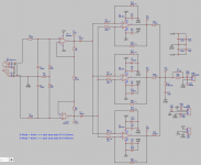
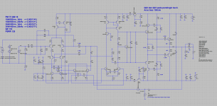
PM me and be sure to include your payment method and location so I can quote you inclusive of fees and shipping. Kubelik is an upgrade of 'PhiDAC' and keeps the same physical footprint of 81mm * 50mm, the maximum height is 19mm. The design is non-oversampling (i.e. no digital filter on-board) and the input format is I2S (three signal wire) at 44k1/16bits. BCK can be 1.4 or 2.8MHz, no MCK is required. Output is CD standard 2VRMS. There's a digital invert function which allows a balanced output DAC to be made from a pair of Kubeliks. Schematic may be found here : lingDAC - cost effective RBCD multibit DAC design

Preferred payment method is via Wise which typically adds a 2% fee. Our receiving currency is CNY, alternatively USD or Euro. PayPal may also be used, in USD but will attract higher fees, about 16%.

Price for a Kubelik kit : 128RMB (~$17.60)

Shipping is in addition and depends on your location and speed of service. Courier (FedEx, TNT, DHL) typically takes 8 - 10 days and e-packet four to eight weeks. Not all locations can be serviced by e-packet though.

FAQs

What else is needed to turn the built up kit into a fully operational DAC?

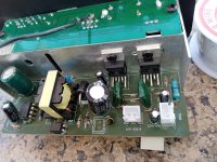
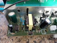
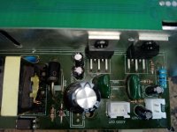
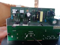
First you'll need a well regulated low noise power supply of 20V rated at 100mA or higher. An LM317-based board set to the correct voltage will suffice if you already have an unregulated supply (like a typical wall-wart). I don't recommend switching supplies due to issues with common-mode noise, its very hard to filter out. We can supply an LM317-based board with either DC (for unregulated DC) or AC (for a transformer) input option.

Second you may need a digital interface card. I say 'may' because some digital sources produce I2S directly (like Raspberry Pi, dedicated SDcard players) but most sources will either output USB (like a PC or laptop) or S/PDIF coax (a CD or DVD player) or Toslink. We can supply a card for interfacing one (or more) of those sources to Kubelik's I2S input. A CM6631A-based card for USB input is the premium choice as it operates under 'async USB' which is the lowest jitter. A mid-range alternative is an interface based on an STM32F4 microcontroller - while still low jitter, its output is not as clean on start/stopping as with CM6631A. In the bargain basement dept are the interfaces based on 'adaptive USB' such as CM108 and PCM270X. The S/PDIF board we recommend handles both coax (two inputs) and Toslink. Further, it has a switched I2S input - this can accept I2S from the USB source. A single pole switch acts as source selector, cycling through the inputs. An OLED screen is an option to indicate the selected input. The one drawback with this board is it needs a 5-12V supply, so a pre-regulator is necessary if fed from the DAC's supply. The simple coax/Toslink board needs a regulated 5V PSU.

Third you'll be wanting some output sockets, typically RCAs so you can connect your finished DAC to your amp or preamp. We can supply these and we're working on a PCB to mount them to make outputting Kubelik to your system easier.

Lastly, and this is obviously optional for a DIYer, is a case. We haven't supplied cases in the past because they're so heavy (i.e. expensive to ship).

USB CM6631A card examples : https://www.aliexpress.com/item/32874113831.htmlwww.aliexpress.com/item/1005004083748180.html
USB STM32 card example : https://www.aliexpress.com/item/1005003632369097.html
USB PCM270X card example : https://www.aliexpress.com/item/4000141799137.html
Multi-input S/PDIF card : https://www.aliexpress.com/item/1005002923079600.html
Coax/Toslink S/PDIF card : https://www.aliexpress.com/item/1005002772984954.html

Do I need special tools to build and test my Kubelik kit?

You'll need some fine diameter solder (0.3mm is recommended), a temperature controlled soldering iron with a fine bit and a pair of tweezers. A magnifier comes in very handy but that depends on your eyesight. Desoldering braid is helpful for correcting mistakes. If you've never soldered SMD before then maybe Kubelik will be too challenging for a first project as there are more than a hundred parts. However none of them are microscopic (the smallest is 0805) and none of the ICs has pins closer together than 1.27mm. For testing you'll need a DMM (digital multimeter).


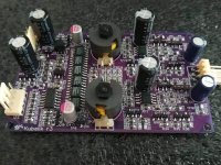
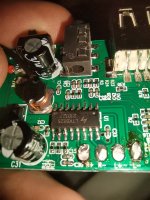
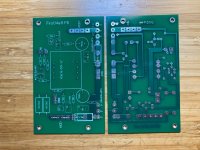
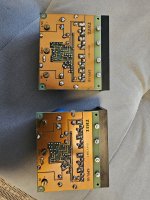
What's supplied in the kit?

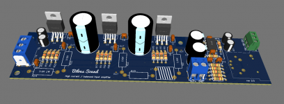
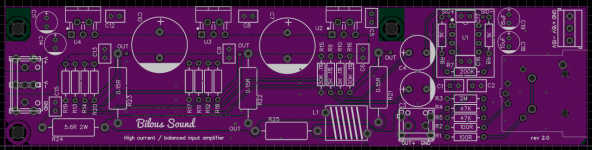
There's a picture directly below of the contents : the bare PCB plus all the components that mount on it (resistors, caps, inductors, LED, ICs etc.). Given that 0805 sized components are incredibly easy to lose, we include a spare or two for each value. Input, output and power are supplied via 4pin Molex-style headers, we supply the mating half with crimped wires to these too.


What, if anything, is unique about Kubelik's design?

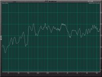
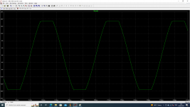
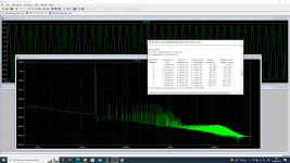
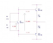
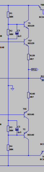
Commercial NOS DACs typically have minimal filtering after the DAC chip itself. Kubelik has two kinds of filters resulting in a 5th order overall lowpass response - a 3rd order passive filter prior to I/V and a 2nd order active filter afterwards. The passive filter prior to any active stage improves subjective dynamics - it means the I/V opamp no longer 'sees' a step waveform out of the DAC chip, rather a continuous signal. The active filter provides 'NOS droop' compensation - meaning you get a flat frequency response to around 17kHz whereas a typical (not every) NOS DAC has roll-off approaching 3dB by 20kHz. It also has headroom to cope with 'intersample overs' which may occur on some heavily compressed recordings. Meaning it won't clip its output no matter what digital input you give it. Opamps are used but their outputs are buffered with discrete transistors as I've found this results in improved instrumental separation when the music gets very 'busy'. Kubelik's DAC chips are 'multibit' but they're not strictly speaking 'R2R' as internally they use no resistors. Instead capacitors are used as elements in the DAC which have their charge constantly refreshed (similar to the DRAM in your computer) to compensate for any drift.


Here's the build and test guide for Kubelik - lingDAC - cost effective RBCD multibit DAC design

Update : The two older versions of the stuffing guide had various errors, here is the up to date version : https://www.diyaudio.com/community/...-rbcd-multibit-dac-design.324933/post-6889095

Attachments

  • Kubelik_kit.jpg
    Kubelik_kit.jpg
    118.9 KB · Views: 2,554
  • Kubelikr3_builtup.jpg
    Kubelikr3_builtup.jpg
    167.8 KB · Views: 2,586

Pearl 3 Cartridge Thread

Thought that it might be useful to have this as a container for things cartridge related. To start off here is a link to Part 1 of a post by Michael Fremer re. cartridge azimuth.

In regards to measuring azimuth I mentioned a little box that Bob Graham markets which I believe takes the left/right channel sums them while inverting 1 channel. Then by playing a mono recording, without a lot of high frequency content, you can adjust azimuth till you get maximum cancellation. Please someone chime in if I got this wrong.

5Ц4С replacement with solid state?

What is the solution to this problem without adding a whole lot of complexity to the power supply?

1) I want to replace the Russian 5Ц4С with solid state rectification in this power supply, and I don't want to jack up the voltage. The voltage drop across the rectifier tube is about 45 volts, correct? How do I get rid of the excess voltage from solid state rectification without harming the power supply performance and preferably improving it? If I can use solid state and get a performance improvement at the same time, great!

2) I also need to drop a little more voltage because the transformer is rated for 110V and I have 120V from the wall. It's a single-ended, 6H8C - EL34 amplifier, and I don't know what the current draw for that might be. The choke is rated at 200mA. Specifications call for 310V and 285V out as shown. Wall voltage is 120VAC going into a transformer designed for 110VAC.

3) If I decide to use tube rectification, what is the expected lifespan in hours for a longer life replacement tube, and which tube type to use? 5Ц4С is rated only 500 hours. I really want the convenience of solid state like my other three tube amps. Only 500 hours is a real pain, and the cost adds up as I put a lot of hours on my system.

I can make simple changes, as the amplifier hasn't been built yet, but I do not want to add a whole lot of complexity to this schematic. There has to be some reasonable solution.

Let's not discuss the merits of or problems with the audio circuit here please. Let's save that for later if I build this kit. Let's focus on the power supply as that is all that matters right now. Power supply design is a subject of its own and a critical skill, so that's why I started this thread.


1700459284870.png


1700460962604.png


schematic raw.jpg

That time I gave a toaster an exorcism

Dateline: Late 70's. My first job in broadcast, a 3KW FM/5KW AM radio station.

The station was built on farmland but the suburbs had grown to surround it. One day I got a call from a very upset but very sweet and very old woman. She was mad that she couldn't NOT hear our station. She had a lot to say so I heard her out, and it turned out she was convinced her toaster was possessed because it was speaking to her.

She lived at the back corner of our property. I had to go see for myself.

The AM station was a four tower array with different daytime / nighttime patterns. Both patterns had a lobe pointed straight through her house. The closest tower to her was all of three hundred feet away.

I was met with the specter of a vintage chrome toaster singing Cher's "Gypsies, Tramps and Thieves", clearly and unambiguously, directly to me. It. Was. Haunting. The lady was right!

Now I don't know if Satan exists or not but I was damn sure he wasn't gonna use my radio station as his unholy vessel. And I can't speak for Cher's relationship with the evil one but I suspect she was an innocent in all of this. Then the toaster told me the weather.

I was fresh out of garlic and crucifixes so I did some LC thing on the powerline and cleansed all the souls involved. Sadly it was before the movie Poltergeist so I didn't think to say "this house is clean".

Marantz PM6005 little/no sound from right channel intermittently

Hello,

Was hoping someone could help me figure out what might be the problem.

I have a Marantz pm6005 that I have stopped using because the right channel would produce no sound or almost no sound. Sometimes if I turned the volume all the way up I could barely hear it. I swapped the speaker cables, tried different sources (digital/analog), different speaker outputs (A,B), cleaned the volume pot, and also replaced the volume pot.

But the problem persisted. Sometimes it would work for a few hours or days then randomly it would stop.

About 1.5 years ago I took it to a repair shop and they kept it for 3 weeks to see if they could reproduce the problem and, according to them, it never happened while they had it. I picked it up and that same day the problem popped up in my system. At this point I gave up on it and started to use a different amp.

I have some time now to really look at it again and would like to be able to locate the problem and fix it if possible, however I'm not sure how to approach this.

Any help would be appreciated.

Regards,
R

Full range speaker for arcade build?

Full size MAME Arcade cabinet build, that will also double as playing blu-ray movies. Started with intent to repurpose very old auto components/amp, but I need to pivot to using full range, and a much more efficient amplifier/speakers. I do not want to have a powered sub, so will probably need at least a 4-5 inch speaker. Will also likely be powered by a not yet acquired simple 2-channel amp board, like the Dayton KAB-250v4 2 X 50W

Any suggestions on a good full range that would have a decent amount of bass? I have been out of the building game for some years now, and never really tried full range designs before. I will be putting a new baffle panel, so will not need to use existing. I also would not be averse to constructing a sealed enclosure behine the baffle for each driver, if that turns out to be necessary to get proper bass response.

I know the HiVi B4N's could be an option, but haven't any experience with using them full range, without a tweeter.

2.jpg


1.jpg


3.jpg

Eve Audio Studio Monitor Problem

Hi All,
Please listen to the recorded mp3 file : I play a pure sine wave (852Hz) . As I turn the level up, an strange noise apears. I have no clue where the problem is. My monitor is SC307 which uses SMPS , DSP and Class D amplification. Any help would be appreciated
2023-01-31-20-28-12-084.jpg
2023-01-31-20-28-47-156.jpg
2023-01-31-20-29-13-315.jpg

Attachments

Simple HEC Amplifier 24VDC

HEC amplifier topology created by Bob Cordell. I'm interested to make simulation using this topology.
It used 24VDC PSU and OITPC compensation that created by Dadod.
Output stage is simple using double emitter follower with driver bootstrapped. Using small transistor in driver,
make loop gain higher because their high hFE.

Any suggestion are welcome.

Attachments

  • HEC45_Loopgain.png
    HEC45_Loopgain.png
    57.8 KB · Views: 676
  • HEC45_clip_20kHz_8Ohm.png
    HEC45_clip_20kHz_8Ohm.png
    49 KB · Views: 333
  • HEC45_THD20kHz_8Ohm.png
    HEC45_THD20kHz_8Ohm.png
    62.3 KB · Views: 668
  • HEC45_SCHsim.png
    HEC45_SCHsim.png
    44 KB · Views: 726

LTSpice Amp Simulation

I came across an issue where a spice model isn't made for a part (the one in question is the TPA3255). I'm not really trying to do any distortion measurements as much as just checking for signal integrity from input to power stage. Is there a way to simulate a chip amp like that using the universal op amps? If not, is there a way simulate the power uplift from the output stage? (I was also considering just doing a simple transistor class A or something just to complete the simulation, but I figured I would ask just in case)

A couple of domes, a ribbon and a compression driver walks into a bar...

The hard dome says "When I'm surrounded by a waveguide, I am smooth and can control my directivity"
1703764301478.png
1703760566622.png

1703760619905.png
Reference:
SB26CDC in custom 6" WG by @augerpro


The ribbon tweeter says:
"Really? I don't need a waveguide to be smooth or to control directivity. And I can be heard from all around"
1703764252807.png
1703758924833.png

1703730771744.png

Reference: Fountek Neo CD3.0 datasheet


The compression drivers says "Well I may not be as smooth, or play as widely as you two, but I'm far more dynamic"
1703764352175.png
1703758841012.png

1703729612580.png1703729689385.png
Reference:
Tymphany DFM-2335R00-08 in SB Audience H225 90°H x 70°V constant directivity horn.


The soft dome says "Well I may be a bit rough around the edges, and I'm not as sensitive, but people have accepted me just the way I am"
1703764446734.png


1703759012587.png


1703730062239.png


Reference: SB Acoustics SB29SDAC centred on a 8" wide x 12" high baffle

edit: correct SPL responses for 2.83V @1m, clickable polar maps for comparisons, example HF units explicitly named

Tube PSU leveling Caps

I am planning to build and LCLC PSU filter for a tube PSE amplifier, and I am debated on 'how good' capacitors I should use in each position to achieve the best sonic performance.

My though process:

C2 is connected directly to the anodes, so the current across it is characterized by large/steep swings and the same frequency of the audio signal, hence I want a high performance capacitor in that position: most likely a high grade electrolytic capacitor in parallel to a film one.

On the other end, C1 current swing frequency is limited by L1/L2, hence my deduction is that any decent capacitor should be good in that position.

1703618445023.png


Any opinions?

Transistor Tube hybrid circuit, will it work like in the simulation?

Hello,

This is my first topic in this forum, my name is Jan, I live in Germany and I'm interested in audio circuits building mostly Headphone and Phono Preamps the last years. I often use tubes, my goal here is to use technology from 70 Years ago and build something that performs on a level close to modern circuits.

My last project was an Phono preamp using INA849 instrumentation amps in the input, ECC83/12AX7 tubes for the LF equalization and OPA output stage. The circuit around the ECC83 was “classic”, a feedback loop was limiting the gain to 10dB in the HF range, at 20Hz the Gain was 30dB. The highest harmonics (K2) with 1.55V output was around -85dB, measured with an AP ATS-2. Not bad for tubes.

I recently found a real treasure, 2x EF12 NOS Tubes that have been build by Telefunken before WWII. I really think about using them in a phono hybrid circuit again using OPAs in the input Stage (AD797 instrumentation amp) and do all the equalization in a circuit around the EF12 where noise is not an issue. They will be in a shielded case because unfortunately the cathode is connected to the shielding of the tube which is basically an antenna.

My goal was to improve the performance of the ECC83/12AX7 circuit. The output of my old circuit is limited to around 5V, after that THD is increasing. Typically for such an circuit, THD is rising with higher output levels.

So I was simulating OPA circuits, really good results I got with the HDAM design. (HV+ = 150V, V+/- = +-24V) To my surprise, using tubes and transistors in the differential amps is not really an issue. Sure, the offset is extreme because of the unbalance in the input stage, many Volts. But with capacitor coupling (an using caps in the feadback loop deceasing gain to 1 at DC) this is not really an issue. To my surprise in the simulation this circuit reaches around -96dB distortion (mostly K2) @ 5V output in 1kOhm. Using 2 tubes in the diff. Amp does not really improve things here, THD is around the same. I'm not sure how this will perform in real life, the tube could be better in the simulation than in real life. For sure this circuit has some problems, if you power the circuit, output will rise close to the V+ rail until the tube is heated. Stability is really good, circuit is unity gain stable with phase margin > 60°

Röhren_Transistor_OPV.png


Would like to hear your opinion! My feeling tells me I will get trouble because of the Tube/Transistor combination in the diff. Amp, I was surprised how good this is working in the simulation.

Thanks!


Best regards,
Jan

mosfet mask probably solution

Good evening, I want to make my first contribution since a lot of information has been obtained from this forum that has helped me repair some equipment.
Regarding the topic about the mosfets with their numbering erased, I have found a xion brand amplifier with the code A4 and the curious thing about this one is that they did not completely erase the surface of the mosfet, leaving a small detail that I now put in photos
When I dedicated myself to researching on the Internet, I found a page and brand of the possible company that manufactures the type of mosfet. I cannot guarantee that it is the only company, but when reviewing the stock, some values agree or are close to those most used by common brands of the same. form attached page link and make your comparisons I hope the info helps and does not affect anyone

https://wxdh-semi.en.made-in-china....nt-Mode-Power-Mosfet-DSG059n15na-to-220c.html

Although at the moment it would be impossible for anyone other than a company to acquire these spare parts, at least there is data to use and compare with those of other brands and look for a possible substitute.

sorry, I used google translator
20231228_012739.jpg
Screenshot_20231228-013306_Chrome.jpg

For Sale LCYLCY-130S 38mm Length Twin-Ribbon Tweeter

https://www.ytaudio.com.hk/brands/product/204/

  • 3rd generation twin-Ribbon technology
  • Excellent vertical and horizontal pointing characteristics
  • Parallel multi-wiring OFC transformer
  • Improvement horn dispersion aluminum front plate
  • Highly concentrate magnetic field neodymium magnet system
  • High power handling

Lightly used, Asking 450USD include posting. n Paypal Fee

Attachments

  • WhatsApp Image 2023-12-28 at 15.35.46 (1).jpeg
    WhatsApp Image 2023-12-28 at 15.35.46 (1).jpeg
    198.3 KB · Views: 58
  • WhatsApp Image 2023-12-28 at 15.35.46 (2).jpeg
    WhatsApp Image 2023-12-28 at 15.35.46 (2).jpeg
    187.9 KB · Views: 57

Open-wing Headphone Crossfeed Stereo Sound

I did a bunch of experiments with crossfeed headphone stereo perception, using Chord Hugo crossfeed function, foobar2000 Meier crossfeed plug-in, and more recently a classic crossfeed circuit (Linkwitz-Chu Moy). I was able to achieve stereo sound, depth perception with singer/musicians/stage in front of me, albeit smaller and nearer than the presentation through stereo loudspeakers. The music separates/delineates more easily and sounds more natural. This effect requires:

(1) twisting the headphone pads "OPEN-WING" so sound comes from FRONT-LEFT/RIGHT (and very slightly above if possible), not shooting straight into ear canal; headphones with 2-degrees-of-freedom work best
(2) EQ DOWN both trebble and bass for a realistic sense of distance, but compensate for bass-loss due to pads not being sealed (try hand-cupping ears or draping flaps over the gap as in picture)
(3) time-delayed crossfeed to opposite channel (I conjecture that additional lower bass delay would be better)

Headphone Stereo Test Prep Music uploaded to China's bilibili (click triangle to play)
LISTEN WITH HEADPHONES "OPEN-WING" foobar2000 Meier Crossfeed set to max, EQ'ed https://www.bilibili.com/audio/am33118121?type=7
original/control for comparison purpose only https://www.bilibili.com/audio/am33116224?type=7

I hope there is interest in this topic. I have found a few circuit diagrams. Crossfeed miniDSP anyone?

1666931886500.png

1666931910978.png

1666931991944.png

1666932058778.png

1666932128494.png

1666932092739.png

Attachments

  • 1666931899722.png
    1666931899722.png
    44.4 KB · Views: 311
  • Like
Reactions: vdljev

Room Gain Spreadsheet

I saw a video of NWAS 2018 where Scott uses an Spreadsheet to estimate the final response of the speaker in the room depending on position.

I have a pair of Mark audio CHN 110 and I would like to use this spreadsheet to estimate the response of the many speakers projects in the mark audio website to see what fits the best in my room

Somebody know where I can find this spreadsheet?

Link of the video in the moment Scott is talking about the spreadsheet:

Login to view embedded media

Thank you

Attachments

  • room-gain.png
    room-gain.png
    28.8 KB · Views: 128

Kenwood XR900-5 Amp. Need help identifying component

Hello folks, I got this amp and someone had messed with it before. Looks like they tore off a transistor and I cannot find a service manual to tell me what it was. Can someone help me make maybe an educated guess? It is the one circled on the left of the first photo. I am guessing it is the PNP version of the CR533 such as a 2SAR533D but not sure. Is it possible it is another NPN like the CR533?

Attachments

  • IMG_8447.jpg
    IMG_8447.jpg
    731.7 KB · Views: 86
  • IMG_8455.JPG
    IMG_8455.JPG
    655.8 KB · Views: 83
  • IMG_8456.JPG
    IMG_8456.JPG
    647 KB · Views: 76

Repairing Kenwood XR900-5 Car Audio Class D amp. Need help identifying missing component

Hello folks, I got this amp and someone had messed with it before. Looks like they tore off a transistor and I cannot find a service manual to tell me what it was. Can someone help me make maybe an educated guess? It is the one circled on the left of the first photo. I am guessing it is the PNP version of the CR533 such as a 2SCAR533D but not sure. Is it possible it is another NPN like the CR533?

Attachments

  • IMG_8447.jpg
    IMG_8447.jpg
    731.7 KB · Views: 87
  • IMG_8455.JPG
    IMG_8455.JPG
    655.8 KB · Views: 81
  • IMG_8456.JPG
    IMG_8456.JPG
    647 KB · Views: 76

Recommendation for a DIY Push-Pull amp kit/PCB?

Greetings friends. I've found myself at the early stages of planning a DIY audio community and have been tasked with finding a suitable amplifier for a DIY kit to be assembled by newbies, and I am here to ask your advice.

I am looking for a PCB-based circuit for a power amplifier, an AB1 Push-Pull amp using EL34/6L6 output tubes and something other than those hard-to-find 7199 to drive em. I would prefer a cathode-biased circuit for simplicity, but will accept arguments for fixed bias design. Above all, I am looking for a DIY project with a high rate of success, so we can bring more people into the glorious world of Tubes.

Any ideas, projects, advice, or warnings welcome.
Thanks!

Will

DIYA Soft Start and Speaker Protect Boards

I purchased 2 sets of these boards in October, populated and used them for about a month until I completed my own custom soft start control board. Purchased and built 2 sets as I have a pair of Aleph J's in bi-amp mode. They are ready to use!
Great price: $60 a pair (1 soft start, 1 speaker protect). Once you let me know your location, I will provide ship cost. I don't charge any extra on shipping, just recovery of cost!

Attachments

  • DIYA-SP.JPG
    DIYA-SP.JPG
    243.9 KB · Views: 175
  • DIYA-SS.JPG
    DIYA-SS.JPG
    244.5 KB · Views: 183

Identifying 211 VT4C or 284D Western Electric?

Hi,
I recently acquired from a relative these two old tubes. searching the internet they look very similar to Western Electric 284D or alternative Amperex 211 VT4C?

Is there any experts who can identify these from internal construction. Photos attached

Thanks!

Attachments

  • IMG_8020.jpeg
    IMG_8020.jpeg
    372.1 KB · Views: 144
  • IMG_8021.png
    IMG_8021.png
    566.8 KB · Views: 136
  • IMG_8022.png
    IMG_8022.png
    554.3 KB · Views: 132
  • IMG_8023.png
    IMG_8023.png
    555.2 KB · Views: 123
  • IMG_8024.png
    IMG_8024.png
    497 KB · Views: 117
  • IMG_8025.png
    IMG_8025.png
    574.3 KB · Views: 121

Vbe multiplier with Si for output stage with Ge

As a follow-up to a recent post: is it possible to apply a VBE multiplier with a Si transistor for a complementairy output stage with Ge transistors?
(See example).
R2 in the circuit must be of a very low value to avoid a melt down of the Ge's. But is it 'controllable' with a certain adjustable value of R1?
Wrapping up: what would be the lowest possible multiplied Si-Vbe?

Answers not needed:
  • how Vbe multipliers work (explanations, doubts of my knowledge about this topic)
  • to have things thermally connected / frequency related issues / driving or loading issues
  • &c
Just: if, how, what can, what not. Nothing else.
It's theoretical.
Practical solutions from the past are appreciated, as long as they fit the scope.


Thanks Andersonix for your very single example.

Attachments

  • GEbias.jpg
    GEbias.jpg
    42.6 KB · Views: 169

HELP! What rank is SONY 2SK6O with A580

Hi Sony VFET experts , I need help determing the rank of 3 vintage Sony VFETs found inside a part unit of a high end vintage Sony VFET amp the VFET is shown in the pic, your kind help will be greatly appreciated ! Thanks! And a very happy new year!🙂 the 3 VFETs are all marked SONY 2SK60 A580, I could not find any info as to what rank they might be .

Attachments

  • IMG_3140.jpeg
    IMG_3140.jpeg
    235.6 KB · Views: 65
  • IMG_3138.jpeg
    IMG_3138.jpeg
    190.8 KB · Views: 67

Phono preamp symetrical push-pull output stage implemented as cascode?

Hello fellow DIYers !

With much help from the fine folks here I begin to master the design intricacies of my vintage integrated amp's MM/MC phono stage. The amp is 30+ years old and the only schematics I could find online were for the revision 3 of the design, whereas my unit is rev. 1. When trying to match the PCB to the schematic there were areas I couldn't make heads or tails, and it turns out there's a major difference on the implementation of the output stages.

Rev 1 implements a cascode stage while Rev. 3 doesn't; of course in both cases the output (TP13) is still taken off the center of the push-pull stage. See below.

Rev 1:
Capture d’écran 2023-12-27 132159.png


Rev. 3:
Capture d’écran 2023-12-27 132308.png


So my question is, why use a cascode at all if the output is not taken off the top transistor's collector? The top collectors are directly connected to the supply so there can't be any output taken there. My guess is to mitigate power dissipation in the output devices since the supply voltages are relatively high (The phono stage shares the same regulated voltage as the power amp section). But if it is for this reason, why drop it in Rev. 3, since that version has the same supply voltages? Simply to save a few transistors I guess... Or are there other advantages I don't understand? A cascode provides extra input to output isolation, but only if the output is taken off the top collector right?

Note that the second stage's output has the same cascode arrangement but with extra filtering capacitors between ground and base of the top transistors :

capture-decran-2023-12-27-134702-png.1251867


Thanks in advance for any insights, and let me wish you all the best for 2024, good health and successful projects!
- Joris

Attachments

  • Capture d’écran 2023-12-27 134702.png
    Capture d’écran 2023-12-27 134702.png
    3 KB · Views: 284

Magic

I have always been fascinated by magic tricks, some I can explain but some are a complete mystery.


From the 70’s onward, I played keyboards in the north of England working men's clubs, providing musical backing to all manner of variety acts.


On this particular evening I was at a club in Castleford, and the artist was Johnny Burnette, A one legged, close up magician I had worked with on many occasions.


I arrived at the club to find Johnny showing a magic trick involving a pound coin, to Alan, the drummer. I was at the opposite end of the dressing room (about 20 feet long), getting changed. After about five minutes of magic, Johnny announced it was probably time to get ready for the show.


Where is my pound coin, asked Alan. Oh, I seem to have lost it, said Johnny. He looked at me and enquired what time it was? I slid back my dress shirt sleeve to look at my watch, TO FIND A POUND COIN SLIPPED UNDER MY WATCH.


HOW? He was never within 20 feet of me. A one legged guy cannot spring across the room. Not hypnotism, I have worked with many hypnotists, and it has no effect on me.


To this day, I am still mystified.

Suggestion BR Cabinet for TangBand W4-1337SDF

Hi friends,

Couple of weeks ago I bought this nice looking TB drivers.
My plan is to put them into a simple BR cabinet.
I Also like to reuse my old Stands that I kept from an old project.

Here 11,5 ltr Net.
Poort tuning 55Hz.

Anyone experience with this driver?

Hereby the first concept.

Attachments

  • Opstelling TangBand W4-1337SDF.jpg
    Opstelling TangBand W4-1337SDF.jpg
    305.2 KB · Views: 169
  • W4-1337SDF - BR - with Stand_page-0001.jpg
    W4-1337SDF - BR - with Stand_page-0001.jpg
    152.8 KB · Views: 189
  • W4-1337SDF - BR - with Stand_page-0002.jpg
    W4-1337SDF - BR - with Stand_page-0002.jpg
    244.4 KB · Views: 196
  • W4-1337SDF - BR - with Stand_page-0003.jpg
    W4-1337SDF - BR - with Stand_page-0003.jpg
    187.8 KB · Views: 191
  • W4-1337SDF - BR - with Stand_page-0004.jpg
    W4-1337SDF - BR - with Stand_page-0004.jpg
    191 KB · Views: 181

For Sale Large haul of drivers (BMS, B&C, 18Sound, Eminence) and turntables

Hi all,

After several years of successful R&D for our loudspeaker company (A for Ara), we have a rather large haul of drivers we didn't end up using in production models.

I'd like to pass these along to the fine folks of this community.

Does anyone want to come visit and take the entire lot away for a very reasonable price? We are located in upstate New York (2.5 hrs from NYC and Boston).

Please reply here or email me directly: db@aforara.com

I'll work on a more exact list of what's on hand. Everything is neatly stored in boxes.

Someone with a bit of patience could easily purchase this as a lot and make a couple grand piecing it out for sale.

OK!
Rob

Turntables: VPI Classic 30th anniversary model, Collins, more (no Garrards, sorry!)

Here's a partial list of the drivers:

BMS Coaxial Compression Driver Model 4590
BMS 4591-16
BMS 4592-16
BMS 4548 Plus-18
Dayton Audio DC160-8
18 Sound 8NMB420S 8"
16" Vintage Woofer
FOSTEX T500AMK2 Horn Tweeter
SB Acoustics 6" SB17NRXC35-4
Radian Audio Engineering Model 760NEOPB-16
Radian 450PB-8
Bastanis Spare Parts (12" Driver)
Bastanis Spare Parts (Compression Drivers, polyester tweeter diaphgram)
Peerless 10.5" Driver P830668
18 Sound Model 8NMB420S
18 Sound 15NLW9500 15"
Eminence Kilomax Pro-18A Professional Series 18"
Eminence Alpha 15
Eminence Omega Pro 15A
Tone Tubby DD 12"
B&C Speakers 21.5" 21SW152-8
B&C DE250-8
Beyma 5CX200Nd/N
Faital 6PR160
SB Acoustics SB29RDNC-C000-4
B&C DE35-8
  • Like
Reactions: taloyd

Philco Gramophone Amp Project

Hello folks!

I've scavenged a working power transformer, output transformer and speaker from a very dead Philco 1224 Gramophone, and my plan is to build a small guitar amp using those as the core. This is my first attempt at design, so I've cobbled together a best-guess schematic which reinvents as little as possible. In that spirit, the rectifier, filtering and output sections have been lifted straight from the original schematic:

original.png

For the preamp, I've settled on a single-jack version of the typical Fender input, cascading a couple of 7F7 tubes, and thrown in the most copied tone stack of all time for good measure. This is what I have so far - I struggled to find appropriate symbols for all the necessary components, so please excuse the obvious substitutions:

1224v3.png

The matching BOM:

bom.png

I want to start working on the component layout, but I suspect there are errors aplenty in the schematic due to my inexperience. I'm hoping that some more experienced people are able to look at my work and suggest improvements to the general topology and/or component values before I go further. Is there anything glaringly obvious about what I've got so far which you would do differently?

As I progress through the build, I'm also putting the source files up on Github too: https://github.com/akhumphrey/1224-amplifier

Logitech Z-5300 Amp Connection

Hi all. First time poster here so if I have this is the wrong section please accept my apologies.

I'm not a DIY electronics person but I do enjoy dabbling in simple projects from time to time. That said I found a Logitech Z-5300 system at a local thrift store. It had all 5 satellite speakers and the control pod so I grabbed it up figuring I might be able to find just the sub on Ebay. Well I couldn't find the sub/amp combo for a decent (cheap!) price but I did find a working Z-5300 amp without the sub. I paired it up with a sub I already have and stole the 120v transformer from another cheap Logitech sub found at the thrift store.

Now as I am trying to hook things up I'm unsure of the proper connection to the transformer. As Wendle states in the thread linked below there are three sets of wires coming out of the Z-5300 amp. Two speaker wires for the sub, 2 power mains that go to the transformer, and 3 wires that go to the other side of the transformer. (These would be the longer green, blue and black twisted set in the photo Wendle posted.)

The problem is that my transformer only has 2 wires for the secondary side of the transformer, not three like what is coming off the amp. So I'm unsure of how to wire these up.

Do I just connect one of them to a single wire on the transformer and then connect the remaining two wires to the remaining single wire on the transformer? It's probably a pretty simple thing, but I'm very much a novice at the electronic side of DIY projects, so any help would be greatly appreciated.

Thanks!

http://www.diyaudio.com/forums/chip-amps/135930-logitech-z-5300-without-remote.html

For Sale KEF SP1587 (Q100) including Cover Ring

Hello together, I am selling 2 KEF SP1587 (coax from Q100) including cover ring. Technically the drivers are very good, see impedance measurement (impedance measurement was redone especially for the sale) and visually they are very good. They were only in use for about 1 year and have been in the cupboard since then. Price will be 200,00 Euro alltogether but is negotiable. Shipment inside EU will be extra 16,00 Euro. Best Regards Johannes

Impedanz Kef.jpg


IMG_9750.JPG


IMG_9752.JPG


IMG_9751.JPG

Choke load phono what if

Normally with phono amps a regulated or choke filtered B+ is advised but here is a what if.

Let's say one uses a decent RC filtered supply and uses a plate choke load on the first stage. In theory the first stage noise contribution is the most critical and high gain is desired there. Of course an active load would be another reasonable option I think.

Would the PSRR and increased gain be sufficient? Something on this order. R load used on second stage to allow DC couple to CF.

ChokeLoad12AY7_Schem.png

Roksan Darius - most ultimate Approach for Stands - other Brands wanted to know

Unfortunately I know only this brand, which have realized this approach to obtain a lowest value of parasitic noise/sonic radiation (still an unwanted effect owing the use of usual MDF pressboards instead sandwich parts for chamber cabinet resp. box enclosure). - go also to
https://stereonomono.blogspot.com/2022/11/roksan-darius-loudspeakers.html
for further information.
Are there also other brands with this kind of fixing the speaker envelope ??

Also the kind of tweeter mounting with springs is of interest (never seen before and thereafter at other manufacturers).

Thank you for advices.

P.S. - for your information:
Also very special was the outdoor unit for the crossover network.
This loudspeaker was equipped with custom made transducers based on follow good known drivers:
1) KEF B200
http://www.zenn.com.sg/Marketplace ima…ch/KEF_B200.JPG
TL Links
2) Seas (similar to K26FX, but only single magnet, supronyl-cone+Ferrofluid)
either
http://www.seas.no/images/stories/vintag…h297_25tnft.pdf
or
http://www.seas.no/images/stories/vintag…h253_1_dome.pdf

Attachments

  • Roksan Darius top-front without cover.jpg
    Roksan Darius top-front without cover.jpg
    277.1 KB · Views: 1,240
  • Roksan Darius top-front without cover-II.jpg
    Roksan Darius top-front without cover-II.jpg
    57.2 KB · Views: 1,103
  • Roksan Darius top-front without cover-III.jpg
    Roksan Darius top-front without cover-III.jpg
    191 KB · Views: 1,069
  • Roksan Darius top-front.jpg
    Roksan Darius top-front.jpg
    272.9 KB · Views: 977
  • Roksan Darius tweeter mounting.pdf
    Roksan Darius tweeter mounting.pdf
    131.9 KB · Views: 202
  • 41429496-198-640x853.jpg
    41429496-198-640x853.jpg
    72.9 KB · Views: 165
  • 940952-9b8ce027-roksan-darius-speakers-for-sale.jpg
    940952-9b8ce027-roksan-darius-speakers-for-sale.jpg
    60.5 KB · Views: 206
  • roksan-darius-lautsprecher rear.jpg
    roksan-darius-lautsprecher rear.jpg
    380.1 KB · Views: 144
  • roksan-darius-lautsprecher.jpg
    roksan-darius-lautsprecher.jpg
    289.7 KB · Views: 184

Choosing between drivers?

Update on a post further down....... now trying to decide between teh Anarchy 7 and the Wavecor SW182BD03/4, or the Dayton Epique 7"

I'm designing a subwoofer for my specific scenario... Several drivers seem to fit the parameters I need.....and model a very similar frequency response in a similar ported box, etc. Trying to figure out if there's something else I should look for/think about before choosing between drivers.

I'm looking for a subwoofer that is...more "musical" and not about punch/shaking the house..... and won't be played at an extreme volume ever (I have downstairs neighbors that I don't want to constantly offend).... I just want to round out the frequency response in my room, more bass than the Carmody S2000 kit will provide. I'd like good low frequency extension, but at relatively low volumes, and I have box size limitations. (SAF, etc)..

Is there something else I should pay attention to that WinISD modeling wouldn't show when choosing between drivers?
For example, I'm looking at the Dayton 6.5" paper cone sub, or the Anarchy 7 aluminum cone sub, and other similar size sub drivers, like the Dayton Epiques, etc..... Is there some other parameter to pay attention to, like cone material? Or magnet size, basket, etc? Or will WinISD lead me astray? (Modeled 40hz performance of one driver vs another won't be accurate, etc?)

Thanks for your thoughts!

-Nate

JBL Synthesis 1400 Design Study

So I’m planning on building a system along these lines for the horn section but instead replacing the 14” woofer with a pair of 8” drivers for an overall narrow presentation. Trying to figure out what JBL did here with the horn…..is it just an existing biradial modded and turned on its side?……JBL says 60 degrees horizontal in their literature but looking at the lens, how’s that possible?

Anyone have any data or points to share?…..I know there’s a member here who has them and I’ve auditioned them a while ago and remember them being really dynamic and engaging

IMG_0308.jpeg
IMG_0308.jpeg
  • Like
Reactions: CinnamonRolls

Looking for a toggle switch assembly Support/Bezel

Hello,
I need a switch Support or Bezel that allows the switches to be recessed inside of the case, here are photos of that part:

unnamed.jpg


This type of Switch Support/Bezel was use in all the Nagra IV line of models but also in equipment of other brands,
here is a photo of some DI Box supposedly made by Helios (closed down in 1979) that used the same type of assembly:


ooFA6I4.png


Does anyone know any info on these parts?
Sources for it?
Or any other equipment that might have used them?

Thank you so much for your help

Passive Phono Pre-Amp Board...Reduced Hum levels

I’m pleased with the big reduction in hum level by removing the original built-in transformer and bridge rectifier and then using a toroidal transformer with an Ebay Chinese rectifier/capacitor board. It required a bigger box too. Hum level is so low as to be inaudible now even though I have increased the overall gain to give an output similar to CD. I also changed the original mica cartridge load cap with a polystyrene one and added a second switchable one to sum to it if required on each channel. Also, this circuit needed DC blocking caps on the output which at best is around 100mV...this value does vary quite a bit with different samples of LM4562. I have also included a series and discharge resistor on each side of the O/P caps as seems to be the norm. Sound quality really is superb and totally transparent using my Ortorfon VMS 30 Mk2 (fine-line stylus). The transformerless late board is now available shown below
P1080517.JPG
phono latest.jpg

Tangband W8-1808 replacement

Hello to all. Having built several rather sophisticated horn-loaded systems, I've recently heard the Voigt Pipe speakers. Yes, I saw that video, too. And now my hands are itching again. And this time, you guessed it right - I would like to build the Voigt Pipe. In order to overcome the inherent weakness of full-range speakers when it comes to very dynamic passages, I decided to add a tweeter instead of relying on the wizzer. Initially, I was going to use the Tang Band W8 1808. But then I thought to myself, If I'm not using the wizzer cone why not use a comparable driver without one? So, here's the questio: what 8" driver would come the closest to the venerable Tang Band W8 1808 but without the wizzer cone?

Hello from Montreal, Canada

Hello everyone,
Just joined the forum! I live in Montreal, Canada ❄️! My lifelong passion for audio has taken me from creating (repetitive) electronic music in the past to enjoying vinyls (with by a glass of whisky 🥃 even better). I've always configured various media players, using platforms like xbmc, Moode Audio, RPi+DAC etc but now willing to take it to the next level (with your help please!).
Big fan of SomaFM DefCon during long nights of DIY'ing 😎 Looking forward to the discussions.
Cheers!

For Sale First Watt power supply cap banks, F6 boards & Jensen transformer (built), B1 front end (built), Alfet Mosfets, Audio transformers

Offer something reasonable. Shipping costs (from Finland) are added to the sum.

Items for sale:

1) First Watt Power supply Cap banks: Dual mono / fully built with Abico connectors

2) First Watt F6 boards designed by late DIY member Georg M. / made in Finland by a quality company

3) First Watt F6 fully built PCB with Jensen transformer /Toshiba JFETs / IRFP Mosfets / Simlic & Wima caps

4) Pass Labs B1 front end / built - only connecting cables needed

5) Toroidy Tranformers 50€ / pcs

a) 2x24VAC 600VA (primery 2x115V)
b) 2x32VAC 600VA (primery 2x115V)
c) 2x50VAC & 1x18VAC 520VA
d) Triadin 2x24VAC 50VA (18 euroa)
- details in the pic

Attachments

  • PS cap bank 2.jpg
    PS cap bank 2.jpg
    533 KB · Views: 165
  • PS cap bank.jpg
    PS cap bank.jpg
    489.8 KB · Views: 164
  • B1.jpg
    B1.jpg
    455.1 KB · Views: 172
  • F6 boards.jpg
    F6 boards.jpg
    482.8 KB · Views: 185
  • F6 & Jensen.jpg
    F6 & Jensen.jpg
    533.9 KB · Views: 185
  • Transformers.jpg
    Transformers.jpg
    374.8 KB · Views: 195
  • Transformers.jpg
    Transformers.jpg
    374.8 KB · Views: 179

Tuning / tweaking TDA2003 BTL Hifi bass power amp

Tuning / tweaking of a Chinese BTL mode TDA2003 Mono amplifier.

It has some mediocre working Bluetooth 2.0 which I do not use.

If Bluetooth is needed I recommend a more modern 5.0 Bluetooth preamp.

I put on the electrolytics 0.1 microfarad foils in parallel. Also same size power decoupling foils between legs 3 and 5 of the TDA chips.

100picofarad on the inputs between plus and minus against oscillation.

There is an smps power supply I left untouched.

I put 1.3 microfarad and 4.5 ohms paralleled in line with the 4 ohm loudspeaker in order to attenuate a fullrange driver and to lower distortion by using Esa Merilainens simple resistor method for a bit current drive. More on this on his website current drive info.

IMG_20231007_120451.jpg

Attachments

  • IMG_20231007_144417.jpg
    IMG_20231007_144417.jpg
    677.2 KB · Views: 159
  • IMG_20231007_120500.jpg
    IMG_20231007_120500.jpg
    528.3 KB · Views: 157
  • IMG_20231007_120505.jpg
    IMG_20231007_120505.jpg
    518.7 KB · Views: 159
  • IMG_20231007_120510.jpg
    IMG_20231007_120510.jpg
    370.6 KB · Views: 148
  • IMG_20231007_120520.jpg
    IMG_20231007_120520.jpg
    449.2 KB · Views: 168
  • IMG_20231007_120524.jpg
    IMG_20231007_120524.jpg
    367.3 KB · Views: 141
  • IMG_20231007_120755.jpg
    IMG_20231007_120755.jpg
    347.2 KB · Views: 156
  • IMG_20231007_123849.jpg
    IMG_20231007_123849.jpg
    481.2 KB · Views: 140
  • IMG_20231007_123824.jpg
    IMG_20231007_123824.jpg
    424.9 KB · Views: 130
  • IMG_20231007_123814.jpg
    IMG_20231007_123814.jpg
    399.6 KB · Views: 139
  • IMG_20231007_121459.jpg
    IMG_20231007_121459.jpg
    379 KB · Views: 161
  • IMG_20231007_120552.jpg
    IMG_20231007_120552.jpg
    455.2 KB · Views: 131
  • IMG_20231007_123849.jpg
    IMG_20231007_123849.jpg
    481.2 KB · Views: 139

THEL 10A regulator pair

For sale a pair of verry good regs for class A amps or other hifi builds.This are good for constant 10A of current and 20A on spikes.I buy some pieces positive and negative regs of this ,years back directly from Thel audio germany but today they are not more produced(verry dissapointing).I use this in all my pass aleph builds and they work without problems and with regulated psu you have way lower noise floor and much more blacker background.In music you have much more details,better and faster bass section and verry silky high section.You will become one positive and one negative reg module,so you can build one psu for up to constant 10A of current.The input voltage is from 20-100V and the output you can set by trimmer from 10-90 volts. In last picture you can see my psu for my aleph 6 build.The price I want is 200 eu for both plus shipping in EU!!!Payment by paypal or bank transfer.For more questions plese contact me.

Attachments

  • 20231019_144459.jpg
    20231019_144459.jpg
    788.9 KB · Views: 245
  • 20231019_144506.jpg
    20231019_144506.jpg
    796.1 KB · Views: 220
  • 20231019_144509.jpg
    20231019_144509.jpg
    670.5 KB · Views: 215
  • 20231019_144524.jpg
    20231019_144524.jpg
    686.9 KB · Views: 217
  • 20230902_124730.jpg
    20230902_124730.jpg
    711.3 KB · Views: 240

Repairing Powered Bookshelf Speakers

I have a blown set of PSB Alpha PS1 powered bookshelf speakers. They popped and died one day when I touched the aluminum volume knob after walking across the carpet with socks in winter. Oof.

They're nothing wildly special, but I like the way they look, and as a tinkerer, I'm thinking it might be fun to get them to make noise again. Most internet folks say it's a lost cause with powered speakers. There's either not enough technical information about the components, making it hard to pair the drivers and crossovers with a proper amp, etc, or the juice just isn't worth the squeeze. I'm not sure. Not having opened them up yet, I don't know what I'll find in there (not exactly easy to open), but could I feasibly turn these into passive speakers, or (possibly) repair the onboard amp and give them new life?

Thanks for your patience. Very new to this side of audio.

Help identify this diode

Hi all,

Have a blown diode from a Eaton 5PX 2000 rack mount ups that needs identifying.

Similar packaging size to your traditional 1N4xxx rectifiers.

Markings on this diode is

PJ26E
p e c 3049

From what I gather pec is now owned by Panjit but I cannot find any info on this

Attachments

  • IMG20231223103123.jpg
    IMG20231223103123.jpg
    138 KB · Views: 107
  • IMG20231223110150.jpg
    IMG20231223110150.jpg
    235 KB · Views: 100
  • IMG20231223103111.jpg
    IMG20231223103111.jpg
    215.6 KB · Views: 109
  • IMG20231223103054.jpg
    IMG20231223103054.jpg
    204.1 KB · Views: 113
  • IMG20231223103037.jpg
    IMG20231223103037.jpg
    214.5 KB · Views: 117
  • IMG20231223103022.jpg
    IMG20231223103022.jpg
    184 KB · Views: 126
  • IMG20231223110235.jpg
    IMG20231223110235.jpg
    341.1 KB · Views: 117
  • IMG20231223110159.jpg
    IMG20231223110159.jpg
    271.2 KB · Views: 105
Projects by fanatics, for fanatics
Get answers and advice for everyone wanting to learn the art of audio.
Join the Community
507,689
Members
7,884,317
Messages

Filter

Forum Statistics

Threads
406,041
Messages
7,884,317
Members
507,689
Latest member
Giannikos