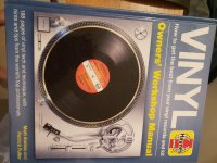
Hey guys, found your educational forum while researching for info on some 'toroidal transformers' I picked up on eBay to use in a 'home electrical testing safety project', and am hoping someone here has some insight to my quest...
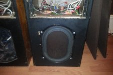
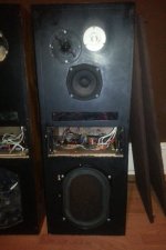
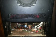
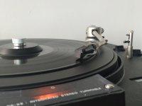
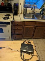
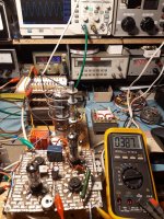
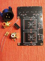
Basically, I've built myself a 'Dim Lamp Isolating box' for testing vintage devices and other power supplies (without blowing them up , or myself) and I need a 240v in , 240v out toroidal (isolation) transformer to drop into the middle of it (see image of my freshly made scary looking death box below).
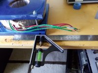
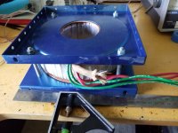
Problem is, none of the transformers came with wiring diagrams and there are LOTS of pretty coloured wires sticking out, and I have no clue what they all do, as I have never even seen one before now. But, I'm hoping someone here does....
Dim Lamp Isolator (aka, The Box of Death)
(has 4 switchable test lamps, LED display, fuse, added trip switch, socket, and TEST/LIVE 'bypass' switch)
The last piece of the build-puzzle is the '
Isolation transformer', so I bought 3 x different cheap eBay toroidal transformers in the hope that at least
one has the requirements for what I need. (i.e. basically only need, 240v AC in and 240V AC out). But the problem is, I think these transformers are so old there are
no schematics in Google to be found.
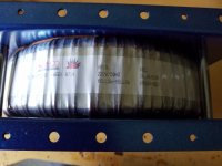
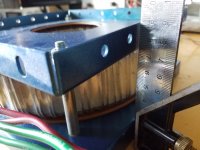
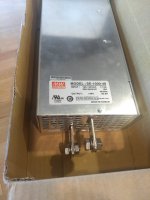
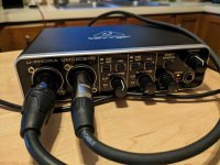
These are the toroidal transformers in question:
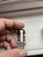
1.
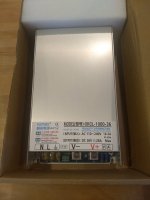
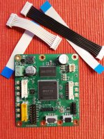
AMETHYST DESIGNS LIMITED -
AD3285T TT3001 0107 (info from seller was; "
300va transformer 3.5kgs and 120mm diameter, 230 v primary, 12v secondary" , but I have no clue about the wiring. I'm not understanding how the Black + Yellow wires grouped in pairs can provide 240v and 12v...? (I'm assuming Brown + Blue are for the 240v input supply?
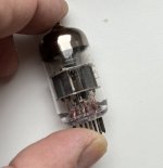
2.
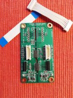
ILP TRANSFORMERS -
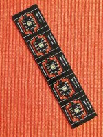
9T029 (that's all i have...?) From online research, I "think" this model (with having a "9" prefix) could be a 625VA , but no clue on wires V outputs?
(
5 x pairs of wires) - Has, 2 x pairs of Red + Blue, then 2 x Pink, then 2 x pairs of Grey + Yellow paired)
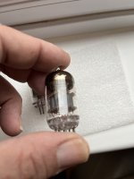
3.
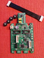
ILP TRANSFORMERS -
9T631 0545 s/n506. Again, from online research, I "think" this model (with having a "9" prefix) could also be a 625VA , but no clue on wires V outputs?
(
4 x pairs of wires) - Orange and Brown seem to be 'sleeved together' on each pair, then Red + Blue paired, and Grey + Yellow paired)
Hoping someone with prior knowledge can assist with, 1. How to test before using any of them, and 2. Wiring colours input/output voltages, for each transformer...?
Cheers guys