My custom tube preamp - Full build advice

I want to run my design's past the forum as this will be my first tube related build.

First the power supply.
The high voltage section:
tube-pwr-hv1.png


Low voltage section:
tube-pwr-lowv1.png


The full power supply PCB:
tube_pwr_pcb_front.png

tube_pwr_pcb_back.png

____________________________________

Now the preamp design:

tube_amp_1.png


First the input is buffed to maintain a constant high input impedance and remain unaffected by the feedback divider that can be changed via potentiometer RV2A.
Simulated THD is nice and low and no sign of obvious problems.

However, I am also considering another design that also looks quite good:
tube_lt_type2.png


Distortion is slightly higher, but now is almost entirely 2nd harmonic. High impedance can also be had (scale R9) and feedback amount can be changed via R14.

What do you think about this circuit? It seems like it might be worth a try. Do I need and additional protection for J1?
Maybe the first amp circuit if better?

Also what is the best way to switch the bootstrap capacitor in and out as this drastically changes distortion and would be nice to compare while listening.
Any feedback is much appreciated.
I can attach ASC files if anyone is interested.

Multiple Small Subs - Geddes Approach

After reading about the AudioKinesis "Swarm" sub system and the Geddes paper on loudspeakers, I am fairly convinced that 3-4 randomly placed small subs are well worth trying in both 2-channel and HT rooms. Geddes specifically recommends multiple and different (not matching) subs to force more randomness (and I assume averaging) of room modes. The Swarms are matched drivers/cabinets.

My question is which small commercial subs would be appropriate for this theory? There are hundreds of small 8, 10, and 12 inch subs that are sealed, ported, etc. Has anyone tried this approach and can anyone recommend a combination of subs? I would like to use the smallest possible subs given the need for 3 or 4 or them in my room.

AULA02014 8" + Celestion CDX1 CD with Harsch XO sorta

I bought these drivers back in end August I think it was, and I've finally got a box for 'em. I've measured up the in box response and played around with the results in XSIM. I still have to order XO parts, and do a final sand and finish on the boxes. But I thought I'd share where I'm at.

I kicked out a thread to discuss the drivers when I ordered them, it's https://www.diyaudio.com/community/threads/tymphany-aula02014-0006-pe-buyout.416365/

Woofer (buyout, NLA) is this 8" tymphany pro audio with a big honker magnet
https://www.parts-express.com/Tymph...-Paper-Cone-Woofer-8-Ohms-299-2265?quantity=1
I got 'em for $17 each!

Compression driver is Celestion CDX1-1446
https://www.parts-express.com/Celes...-Compression-Driver-8-Ohm-299-2257?quantity=1
This one is also a buyout but I think the same driver is available regular production.
I've got it on this JBL Selenium HM17-25 https://www.parts-express.com/Selen...al-Horn-60x40-1-3-8-18-TPI-264-308?quantity=1

I have modeled it up in 30 L and ported at 60 Hz. Software wanted to suggest smaller / higher, but I'm trying to get this thing to dig down far enough to cross to my sub. I have 3D printed a port according to geometry in this Harmon paper about optimizing ports. https://www.diyaudio.com/community/attachments/harman-port-study-pdf.893225/

I was trying to conceptualize how I'd put this speaker together, and I thought of trying to time-align the drivers, so I measured the acoustic offsets. The horn+tweeter came out 70mm behind the driver (mounting features in the same plane), which was more than I was expecting. I had a little thread to consider options about that https://www.diyaudio.com/community/...nique-for-horn-out-front.419357/#post-7851615 eventually I remembered that @xrk971 has a crossover topology that wants the tweeter a fair bit delayed WRT the woofer, and that's the Harsch XO, he's got a thread about it here - https://www.diyaudio.com/community/threads/s-harsch-xo.277691/. I was considering a 2kHz XO, and the delay according to the Harsch thing was 85mm, so another sheet of plywood for the woofer to sit on was just about right.

So that's about how I dreamed this one up! Here's how it looks...
SpkrFront2.jpg
SpkrBack2.jpg


Ah... every thread is better with pictures. I've got roundover I think it's 1" on the vertical corners. Boxes made of arauco ply 3/4" from Home Depot, I'm still trying to decide how I'm gonna finish them. I like the lines from the ply on front.

Ground plane, on-axis (spkr tilted down to point at the mic) 2m distance acoustic measurements look like this
Measurements No XO.jpg


THD is good on the woofer, and FR is fine to 3k, but I think that is a low baffle step from 100 to 500? Speaker is 12.5" wide. Anyway that shift ended up being around the upper of the two impedance peaks in low woofer response, that made it kinda tricky to correct passively. FR on the tweeter seems pretty nice, but measurement looks like kinda high 2nd order HD.

I've been fiddling with the XO sim to get something I like.... here's where I'm at.

AULA-H2.2k-3.jpg


Initial idea was to have the cross at 2k, but in the course if trying to make it work I have floated up from there. So I think my offset is actually a little too much, and my phase peak is a bit larger than it might have been.

If you go for this sort of XO, it is (quoted from XRK's thread)...

1. Set the low pass filter for the woofer as a 4th order Butterworth at central frequency, fc for the XO centerpoint.
2. Set the high pass filter for the tweeter as a 2nd order Bessel at fc.
3. Set the delay of the tweeter equal to 1/2 of the period of one cycle at fc.
4. Use all positive phase on woofer and tweeter.


Here's what I've learned: 2nd order -acoustic- roll off is pretty slow! 2nd order electrical is normally fine, but when you are looking at the acoustic rolloff that happens naturally that doesn't leave much space to put in electrical protection. So I ended up at higher F than I was initially targeting. It looks like 2nd order electrical on the CD but it's pretty low Q, that inductor is only helping out at lower frequencies. Impedance compensation on the CD can help you get the shape theory wants.

I think I've attached the XSIM file in case anyone wants to play along.

I'm looking forward to hearing these, but I haven't pulled the trigger on XO parts yet. Every time I buy parts a couple days later I'm like "you know what I SHOULDA done...?" so I'm still meditating on it.

What do you think?

- Adam

Attachments

Centure 24: digital 4-Channel DSP Amplifier with Class-H option

Hello DIYAudio community,

Couple of years ago I’ve designed a DSP Class-D amplifier called Centure 21. It has got ADAU1452 DSP, TAS5548 as I2S->PWM modulator and 4 output channels, with 4 more available on the "PWM" header.

and photo of the prototype:
1734794922830.png


on the left there is Amanero header, which can be used for amanero module to have just USB 2 ch input, or my York interface. There was also header on the left side with S/PDIF and I2S which are connected to ADAU1452. The purpose is to connect daugter boards with different input interfaces: ADC, AES/EBU, TOSLINK etc. The module was used primarily for home audio.

After some discussion here on DIYaudio with @florentg (https://www.diyaudio.com/community/...-dsp-bluetooth-aux.376006/page-2#post-7719605) we meet in person played with the Centure 21 and discussed what we could do in the field of DSP amps, the specs and software and ways to build something better. Recently TI announced a new amplifier IC TAS6584 which basically combines I2S→PWM modulator and the output stage but also have some quite interesting features, like the H-Class power supply control.

So a new device was developed 🙂

Structure of Centure 24:
image (1).png


The structure of new version is quite similar to previous one: there is DC-DC for output stages, a DSP chip and MCU to control and monitor the system. The main difference is in more advanced diagnostic and monitoring of the sysem, thanks to TAS6584. Also since TAS6584 implement H-Class control together with the DC-DC, this fetature is also available and can be enabled/disabled via software. Here is demo from TI: https://www.ti.com/video/6287333584001

photo_2024-12-20_19-34-06-removebg (1).png


This time the module designed such that it can be also used as the plate amp: all the interfaces (S/PDIF, I2S, I2C) are routed to headers and supposed to be connected to interface board (which is not ready yet):

plate.png


The amplifier has 4 channels which can be configured as 4xBTL, 2XBTL + PBTL or 2xPBTL. So it allows fleaxible configuration for multiway systems. The nominal output power would be around 200W for all channels combined, the peak power of course would be higher. Not all measurements are done, only up to 100W/channel.

There is also software development going on which is based on the York interface (thread on DIYaudio: https://www.diyaudio.com/community/...tichannel-input-output-interface-york.413504/)

image (2).png


Live monitor of Class-H operation:

image (3).png


Measurements, experiments with the H-Class control and config software features will be posted later.

New Doug Self pre-amp design...

Just a heads-up...

This month's (UK) Elektor (April 2012, dropped on the mat this morning...) has a long article by Doug Self with, what he says is, his first published new pre-amp design since 1996. Side notes on Peter Baxandall, references to "Baxandall and Self on Audio Power" - all sorts of stuff. Pt. 1 is about design methodology and his pet subjects of sources of noise & distortion - does include the schematic though.

Kind of fun... (if you are a Self-devotee)

Specifications
Test conditions: supply voltage ±17.6 V; all measurements symmetrical; tone control defeat disabled.
Test equipment: Audio Precision Two Cascade Plus 2722 Dual Domain (@Elektor Labs)
THD+N (200 mV in, 1 V out) 0.0015% (1 kHz, B = 22 Hz – 22 kHz)
0.0028% (20 kHz, B = 22 Hz – 80 kHz)
THD+N (2 V in, 1 V out) 0.0003% (1 kHz, B = 22 Hz – 22 kHz)
0.0009% (20 kHz, B = 22 Hz – 80 kHz)
S/N (200 mV in) 96 dB (B = 22 Hz – 22 kHz)
98.7 dBA
Bandwidth 0.2 Hz – 300 kHz
Max. output voltage (200 mV in) 1.3 V
Balance +3.6 dB to –6.3 dB
Tone control ±8 dB (100 Hz)
±8.5 dB (10 kHz)
Crosstalk R to L –98 dB (1 kHz)
–74 dB (20 kHz)
L to R –102 dB (1 kHz)
–80 dB (20 kHz)

Iron Amp by Michael Rothacher Power supply suggestions?

Ironamp schematic.jpg

I would like to build this amp and I need the power supply ( about 100v 200ma on the v-fet but a bit higher because the Output transformer primary impedance ) to be particularly silent since it is connected to a compression driver with 113db of sensitivity. I was thinking of using a CLCLC power supply (to have few mV of ripple) and I was wondering if the use of a Saligny power (HVHF in this case) could be useful.
My problem is that at most I can use PSUD II and therefore I have no idea how to model a power supply with a Saligny bridge. Any suggestions?

diyAB Amp - The "Honey Badger"

I have asked member ostripper to lay out a Class AB amp officially called the "diyAB amp" ( nicknamed "the Honey Badger" ) using many of the best characteristics of amps of this type that have appeared on our forums, so that we can feature it in the diyAudio Store. He has agreed to give it a go, is really interested in comments to help it be a paradigm of its type, and will be posting here very soon to describe where the design is at this point.

So pile on!

Mark
"Variac"

Build thread for diyAB Amp: http://www.diyaudio.com/forums/solid-state/211905-diyab-amp-build-thread.html

Miscellaneous designs - Markaudio, Fostex, TB, Dayton, SEAS etc

As per the title really.

I work up far more designs than I usually publish on the forum or ever normally see the light of day elsewhere. Some were done at request, some are simply quick design exercises or checks / investigations, some I can't actually remember the reason for doing. I don't always have time to systematically catalogue things, and they can end up lying around on one of my HDDs for months until I sort through them. I'm currently in the process of going through one of my old external USB HDDs before it's recycled & found quite a few. Most weren't worth bothering with, but there were some more practical / interesting ones so rather than scrapping them, I thought I'd start a thread that can essentially be a bit of a dumping ground for misc. designs that I've done that either haven't found a home elsewhere, or that have previously been posted but got buried on other threads, so at least they're concentrated together.

Advance warning:

-There is little consistency in the layout / sketches. I'm lousy at CAD, and there's no way I can inflict more than a small portion on the long-suffering Dave to draw. In these cases, it's probably not worth a high quality drawing anyway. I've quickly re-saved most into png format to save space & done a little tidying if needed. The rough date is sometimes mentioned, sometimes not, depending if I remembered to add it at the time. Sometimes damping is shown in the sketch (all done in Windows Paint so they are very basic), sometimes it isn't, but I always refer to it in any accompanying notes. Same for bracing or vents / ducts; I often don't show the dimensions but they're in the notes. There may be some errors; I don't think there is anything major though. Normally I work in Imperial & assume a baseline 3/4in build / sheet material thickness. Some are metric, in which case the assumption is 18mm. Change as desired, providing the internal dimensions are not altered.

-Most of these are physically quite simple; vented box variations, some MLTLs or ML-Voigts etc.

-I'll add periodically as / when I find things. All are free for personal use.

Schematic or service manual Sonographe SC25

Trying to find out what size this resistor is in my unit. I am having trouble figuring the color code on this resistor it is in a Sonographe SC25. My unit was modded and I am going back to original, but this resistor and the cap next to it were removed and would like to replace but do not know size on both. Thanks for any and all help in advance.Screenshot 2025-05-02 at 21-33-56 Conrad Johnson Sonographe SC-25 &amp SA-250.pngScreenshot 2025-05-02 at 21-30-41 L'Audiotecnico Conrad Johnson - SC25.png

Why cant I use SMPS for TPA3255?

Hi,

I just bought two pieces of Aiyima 07 TPA3255 amplifiers and also bought 48V SMPS for them. But later learnt that the manufacturer advises not to use SMPS for it but use power adapter instead. Well, first of all, what's the difference between them, technically both are SMPS only?
Click this link for the actual listing
1746201637679.png

Thanks and Regards,
WonderfulAudio

Direct Digital Power DAC (DDPD)

Hello,

as I promissed just to share with you concept from YU3MA forum, this is pulse densinity modulated H bridge power dac driven by dsd64, in short it's an full bridge class D direct digital power amplifier pulse densinity modulated, contain no opamps... etc just directly flow DSD bits to the full bridge, more comparable to an water flow boiler with diference boiler flow hot water but this one flow dsd bits. : ) Tested up to dsd256, it might work on dsd512 too? Concept contain variable power supply as a volume control, 1.25V to 5V range. You need Amanero usb combo and you need DSD tracks in order to play sound trought this dac. You will be surprised by the huge dynamics and holographic unchanged and detailed sound! The power of this dev concept is in the range of 3 to 5 watts and I do not recommend more, you simply need to first adjust the current with CC pot by shorting +5V at the one of the 8 capacitors for example C165 to gnd with an ameter until your ameter display value close to 1A, than you are ready for sound testing. Here is soome pictures and videos and more details about further concept . Its fully diferential! Optimised for 8 ohm speakers! Not measured but I have bought Cosmos ADC and when I finish some concepts and when I get ready for measurement I will do it, hope somebody do it allready. Gerber, bom and schematic is in atachment. Please pay atention to R72 resistor, change it for 2mA, ohm law yuor input dc voltage and calculate resistor value for 2mA! Enjoy!

dsc_0141-jpg.1093735


Login to view embedded media

Attachments

Proof that anyone can, Unity Horn

IMG_6797.jpg
IMG_6789.jpg
IMG_6786.jpg


Introduction:
Hey guys, been a long time lurker here. I've been pretty busy lately working on a dirt cheap unity horn project for my desktop setup. The entire horn is going to be 3D printed for ease of assembly. A lot of effort has been put into making this build as cheap as possible. I actually think this might be one of the cheapest unity horns out there. I have two goals I want to achieve for this project.
  1. Wide phantom image and constant directivity. I have lots of pc-monitors in-between my current speakers. The problem with this is it forces my speakers to be very far out from the listening spot (around 150 degrees). Unless you are seated perfectly between the speakers, the sound-stage collapses. It is my belief that a wide CD horn will fix this.
  2. Provide an affordable MEH so that more audio geeks can hear these awesome speakers. I really love unity type speakers, the linear phase, constant directivity, and acoustic filtering provide a lot of benefits that are hard to achieve otherwise. My dream is to eventually make this into a diy kit, but I'm not sure if I have the resources to make this a reality.
Woofers:
This all started when I discovered these little Dayton TCP115 woofers. I was working around in hornresp and pasted the driver profile by mistake. Low and behold, the simulation had an extremely wide bandwidth for such a cheap driver. The high xmax is also nice for going low so I was able to make this design a 2 way and still get decent bass.

Tweeter:
Most, unity horns seem to use compression drivers. Since I don't need high output and need a cheaper option I decided to go with something different. The XT25 is what I am using for now and it seems to work quiet well. By using a really large horn I was actually able to push the crossover frequency quiet low (around 1.2khz). I know, I know, that crossover is insanely low for this tweeter. I have more data on why this works; will post more later. Right now I am having trouble getting accurate distortion measurements to confirm my theories.

Measurements:

Around_15_Degrees_off_axis.jpg
Polars_Unsmoothed.jpg


Around 15 degrees off axis after some quick EQ. The dips at 6k and 10k appear to be from a problem at the throat which are being fixed in the next version. The next box is also going to have a flush mounted horn and 18mm round overs on the baffle. I am hoping this will improve those ripples. You can't just EQ those ripples at any one angle. As you can see the dips move around depending on your angle off axis.

Quick_and_Dirty_Polars.jpg


1/3 smoothing of the same graph. I don't know what the exact angles are, it's really just a proof of concept to show the directivity is being controlled. The light green line is around 60 degrees, which is why it is so low in level.

Things I still need to do:
Throat optimizations, active xover tweaking, passive xover development, take more accurate polars outside, measure below 200hz, port it (maybe?), make it pretty.

Tannoy PBM 8 upgrade?

Hi everyone.
I have a passive home studio system with a pair of older (well maintained) tannoy pbm 8, along with an equally well maintained pair of yamaha ns 10, and i’m trying to find the most appropriate upgrade on the tannoy pair.
Passive, 8’’ woofers, similar frequency response and not far more expensive. And of course i would prefer older used stuff. Not necessarily studio grade. Just different and maybe better than the pbm 8.
Any suggestions?
I guess older yamaha passives 8’’ must be pretty similar to the ns 10 (even if they are one of a kind in a way…).
Dynaudio passives are the first that come to mind. But i guess there are more, maybe cheaper and maybe better.

Thanks.

Where to buy mosFET clips

Hello,

I am looking for specific clips that I can not find anywhere. They are for car amplifier and I have seen them in many amps. But I have cheked Mouser, digikey etc. and I can not find them.

I have seen others to look for them also:
https://forum.digikey.com/t/replacement-thermal-mosfet-clips/7461

Does anybody know where to get them or some part number?

Clips can be seen here:
https://amp-performance.de/en/Audio-System-HX360-2.html

Thank you

Attachments

  • IMG_20250430_174246.jpg
    IMG_20250430_174246.jpg
    289.9 KB · Views: 18
  • IMG_20250430_175925.jpg
    IMG_20250430_175925.jpg
    226 KB · Views: 17
  • IMG_20250503_205858.jpg
    IMG_20250503_205858.jpg
    1.1 MB · Views: 15

EQ1616D Phono Amp

Stereophile Class A recommended components..

Class A
Best attainable sound for a component of its kind, almost without practical considerations; "the least musical compromise."


Recommended Components 2021 Edition Phono Preamplifiers | Stereophile.com

EQ1616D were nearly old out. The next production will be in July 2021. --> April Production was SOLD OUT.
The Next Production is July 2021.
If you want to reserve a unit of EQ1616D, please let me know.
Thank you for your support!!

Price $985.00 Kit
Assembled Version $1,645 with 2 VCAP ODAM 2.2 (assembled by Sunvalley Japan)


Stereophile Review - November 2020 edition
Gramophone Dreams #42: Sunvalley Audio SV-EQ1616D phono equalizer | Stereophile.com

Sunvalley SV- -EQ1616D 115/230V version (Point to Point Phono amp Kit)
Made in Japan

Price $985 KIT Version
Price $2,050 ASSEMBLED Version ( Assembled by SunValley Japan with tube set (Gold Lion ECC83/B759 X 2 + Brimar ECC82 X 1 + LINLAI/COSSOR WE 274B) + VCAP ODAM 2.2 X 2 (output Cap)
Price $1,585 (assembled version w/o tube set . VCAP ODAM 2.2 X 2 included) + shipping
Assembled Version

This kit does not come with tube set. The following 3 combinations are recommended.

(Plum set)
Gold Lion ECC83 / B759 x 3 + LINLAI 274B
Standard combination. Natural charm

(Bamboo set)
Gold Lion ECC83 / B759  x 3
WE 274B
Powerful midrange

(Pine set)
Gold Lion ECC83 / 12AX7  x 2
Brimar 12AU7 x 1
Cossor/Linlai WE274B x 1
Vcap ODAM 2.2uF [2 pieces] x 1
Superb harmonics


● Phono equalizer that emphasizes sound quality
● 2 input systems that are ideal for using 2 turntables
● Output: 1 system (MONO (L) / STEREO switchable) * MONO: L channel Input → L / R dual output
● Compatible with MM / MC cartridges (MC input: head amplifier) * MM: 47kΩ, MC: 20Ω to 50Ω
● Gain: MM35dB, MC + 22dB
* Gain can be selected according to the output voltage of the cartridge ( When HIGH / LOW) or LOW is selected -4dB (MM) /-2.5dB (MC)
● Vacuum tube: Amplification stage (V1 / V2): 12AX7, 2nd stage (V3): 12AX7, 12AU7, 12AT7 can be selected arbitrarily (according to your taste)
* The standard is all 12AX7, and if you want the smooth texture of high frequencies with a high output cartridge, 12AU7 is recommended only for V3 ( I have RCA clear TOP or Brimar to pick)
● Rectifier: Standard / diode module, option / various rectifier tubes (5AR4, 274B, 5R4 etc. can be used) ( I have LinLai 274B, WE274B, ACME 274B or ELROG 274B)
● Turnover frequency adjustment: Switchable
  → Compatible with RIAA, old AES, COLUMBIA / old NAB, LONDON, EU SP , US SP
  * Not only turnover frequency but also low frequency characteristics can be changed simultaneously according to each EQ curve.
● High-frequency roll-off adjustment: ON / OFF selection type
* When ON: Continuously variable (corresponding to all EQ curves), When OFF: No attenuation (for SP LP)
● Detail assembly guide included
● Assembly difficulty: ★★ ★★ ☆ (for intermediate to advanced)


Size mm (including protrusions): W250 x D225 x H135
Weight: 3.8 kg

UPgrade options:
Gold Lion (ECC83/B759 X 2 + Brimar ECC82 X 1) = 215

LinLai/Cossor WE274B $265

VCAP ODAM 2.2 X 2 $85 each


Sunvalley SV-Pre1616D Point to Point Prject

Lundahl MC Transformer will be available Soon... 3 versions with Amorphous core - Standard, OFC, or Silver .
TUBE RECTIFIER


VCAP 2.2uf ODAM

YOU can use sold state RECTIFIER


VCAP 2.2uf ODAM

Operation Manual 2 & 3

Circuit type: CR type phono equalizer
・ Input: 2 lines
・ Output: 1 system (STEREO / MONO switchable)
・ Corresponding cartridge: MM (47kΩ), MC (50Ω)
MC boost: FET head amplifier
・ Gain: MM36dB ~ 40dB, MC + 25 ~ 32dB (determined by prototype)
・ Vacuum tube: amplification stage: 12AX7 (2), follower stage: 12AX7, 12AU7, 12AT7 can be selected arbitrarily
・ Rectifier: Standard / diode module, option / various rectifiers (5AR4, 274B, 5R4, etc. can be used)
・ Turnover frequency adjustment: Switchable (supports RIAA, EU system SP panel, US system SP panel, AES, NAB, COLUMBIA, etc.)

・ High-frequency roll-off adjustment: ON / OFF selectable (When ON: Continuously variable RIAA and other curves are supported)
(Specifications are subject to change without notice)

Specification :
https://www.kit-ya.jp/user_data/SV-EQ1616D.pdf

Phono + Line stage Amp (Filter - solid state diode or optional 5AR4)

Miles Davis "Someday My Prince Will Come" (Columbia / old NAB curve) 1961


"Art Blakey And The Jazz Messengers" (AES curve) 1958


Miles Davis "Kind Of Blue" (Columbia / old NAB curve) 1959


Sonny Rollins: A Night At The "Village Vanguard" (AES Curve) 1957


Playing LP with the proper curve will make a big difference in the strength of the sound to anyone listening, especially the freshness of the mid-high range,

Since the sound quality of the LP differs depending on the label and recording , the SV-EQ1616D cannot only turn on / off the roll-off (high frequency level attenuation
characteristic) of 1 kHz or more, but also can make fine adjustments when the roll-off is ON. Since it is also possible to control the tone, you can enjoy each LP with the
optimum sound quality.

  • Like
Reactions: zettelsm

Burson v7 Vivid review

Burson audio team sent me 4pcs of V7 vivid single opamps to test it in my phono preamp (i'm using t-phonum mk2 clone).
I have received them recently and tested only for few hours so maybe I'll extend this review in a while.
They come in cardboard packing, with additional extension sockets and rubber bands to hold it together with opamp. And a sticker, to make your device look more pricey )
My first concern was whether it will fit in my phono preamp casing, but luckily it fits perfectly )
How it sounds? Well that's a hard one for me because I'm comparing v7 with v5i (because I bought v5i to replace ne5534) and there is no such huge difference as it was between ne5534 and v5i.
First - the gain is a little lower than v5i and I guess that's the reason why v7 can be only applied in MM phono preamp.
Second - there is less noise in background, the difference is even bigger than the difference in gain but still they both have much lower noise level than the silent groove. Also with v5i I can hear some radio transmission (there is a cable radio line in the building), with v7 - not even a hint of it, but probably it is more gain related.
Third - V7 produce more heat than the v5, but it is just warm to the touch (casing is metal), so probably v7 consume more power.
And finally - it sounds more detailed to me, and a bit brighter in mids. So far in general it feels like low to zero feedback tube amp
I'm eager to test it in MC mode as soon as I get MC cartridge, maybe in combination with v5i to achieve acceptable gain.

Attachments

  • burson_v7.jpg
    burson_v7.jpg
    79.3 KB · Views: 167
  • IMG_20240516_152145.jpg
    IMG_20240516_152145.jpg
    196.9 KB · Views: 138
  • IMG_20240516_150927.jpg
    IMG_20240516_150927.jpg
    485.8 KB · Views: 148
  • IMG_20240520_145228.jpg
    IMG_20240520_145228.jpg
    154.8 KB · Views: 143

For Sale Speaker Sale

Blaupunkt P652c 6 1/2 two way. Pair NIB $50.00

4" Coated Paper Mid/Woffer P/N 55-1200 8 ohm/40W. Used pair $40.00

3" Paper Tweeter Bukooo DO7776/2M24 8 ohm 40W Used pair $20.00

1" Mylar Dome Tweeter P/PN11028-584560 New $25.00

All OBO, Paypal plus shipping.

Attachments

  • Blaupunkt_P652c.jpg
    Blaupunkt_P652c.jpg
    224.4 KB · Views: 610
  • Blaupunkt_P652c2.jpg
    Blaupunkt_P652c2.jpg
    155.2 KB · Views: 605
  • 4inchMID.jpg
    4inchMID.jpg
    165.1 KB · Views: 594
  • 4inchMID2.jpg
    4inchMID2.jpg
    144.6 KB · Views: 585
  • 3inchpaper.jpg
    3inchpaper.jpg
    74.7 KB · Views: 584
  • 3inchpaper2.jpg
    3inchpaper2.jpg
    118.6 KB · Views: 149
  • MylarTW.jpg
    MylarTW.jpg
    146.8 KB · Views: 141
  • MylarTW2.jpg
    MylarTW2.jpg
    119 KB · Views: 139

Big HE 3 way sealed (4350 / Pitt & Giblin inspired)

Hello guys, I wanted to share my last build, maybe get some feedback.

I was very happy with my nupole (nude dipole on a pole).
Took the dipole path few years ago, for a very evolutive and iterative process with 20+ versions.
The last one was very very satisfying, but I couldn't stop thinking that it might all be based on biases that evolved in parallel.
Friends and even more Hifi enlighten friends enjoyed it too but could not invalidate my choices.
Also the room evolved with the build, and I know this could hurt the end result, or know that I might have to change few things to better work with a box system, but this is for later.

So I decided to try one last time a boxed system.
I initially started with a simple 3 way sealed, classic look that I like, reasonable size as I thought I wouldn't need much SPL.
First prototype was not very pleasant.
Build a second one a little bigger, not much better.
It felt weak, not enough presence in the room, no filling/no feeling.
I'm sure it could have been better with a lot of tune work but it was just not a good enough starting point.

So, for the time and money involved why not go nuts with the biggest I could fit in the room?
Always love the jbl 4350 serie, so this was the first inspiration.
And really love the 
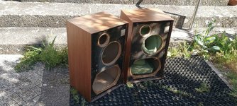
Pitt & Giblin stuff, this was the kick in the back I needed to decide for a 3 way sealed with horns.

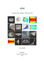
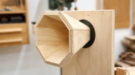
In the same time Nicolas opened his online shop on Audio Horn so after discussion I went with the X-28 with roundover option.
2x15" woofer sealed for the bottom to try sub-less first, and allow a future port if needed.
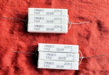
Studied a bit what kind of woofers could play nice in a sealed box of 100L, at reasonable prices, and went for the SB 15OB350 (very cheap and the simulated response was not much better with the 15SW800).
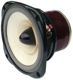
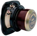
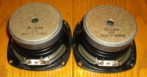
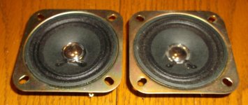
Then what kind of midrange could play nice between 200-1500Hz with this horn? The PHL3040 seemed a good fit, among others.
I could have gone with a more low midrange oriented one but wanted to try.


Construction was fun, I'm very impatient and usually start with minimal plans, my way to deal with surprises during the process.
Very useful informations were found online around the jbl : plans, clones, video build etc so I had a good idea how to do it.
I also have a limited wood work knowledge, practice and tools, so I again went the ikea route, for a good enough finish with minimal work.
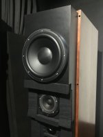
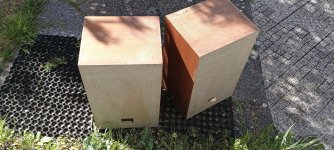
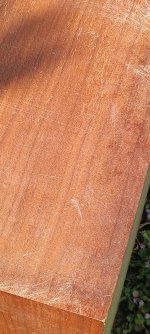
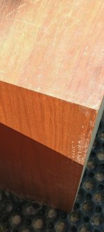
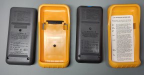
So I took some door panels, full particle boards with a fake but nice walnut finish, for the outer box, and Eket boxes resized for the horns.
22mm plywood for front and back, with mdf as second layer where needed + bracing.
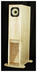
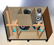
100x70x40cm, 280L outside and around 220-230L inside, with a 15L. box for the midrange, bracing very similar to the the jbl, all panels in their longer length + support around the woofers. Kind of light bracing as a start, that could evolve if needed.

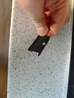
Bought few tools to get a nicer result, a little router that was very easy to manage and surprisingly strong enough for the big holes, and a plunge saw with rails for better cuts as my regular circular one didn't cut straight on longer runs.

I've built one at a time and was ready for 3 thinking I will mess the 1st too much, but fortunately it was ok and I was able to do 2 very similar in a row. The second one is a little cleaner on edge cuts and details but is 95% the same I'd say.
To do better I would have to study real wood working, or ask for help.
It sure could be built better but it is solid, where I thought it seemed a little weak I would just add some wood.
If I redo one I would go even bigger as finally their size is fine.

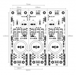
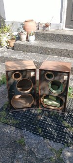
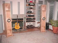
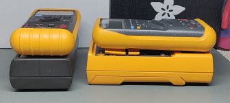
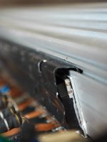
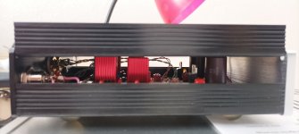
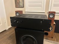
Few pics of the boxes:

IMG_3083.JPG
IMG_3082.JPG


IMG_3067.JPG IMG_3068.JPG IMG_3069.JPG IMG_3071.JPG


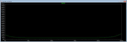
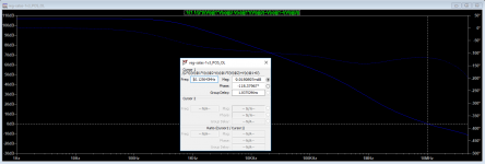
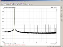
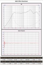
And some of last rew stuff:

- Nearfield response per driver, no eq needed on the midrange, big +12db boost on the woofers.
Did a bunch of off-axis measurement to get a feeling of the response, not shared here I just don't always save them and almost never "tag" them anyway.
Planned for a 1200ish Hz crossover for the horn, but surprisingly the 10" midrange off axis response was too good high up, or not enough directive if I can say to get a good match with the horn, so went with 1400Hz.

nearfield.jpg


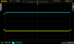
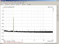
- Sum and timing made at listening point with mic and ears, before and after eq with averages:

Avg.jpg

EQ.jpg


I first heavily stuffed them but at the end removed everything. Clearly lost 4-5db with stuff above 50hz for just a little more low end.
And without, compensated by eq, it just sounds better.
I didin't notice much resonance, nor saw any in the impedance sweeps, just something to check for later.
Still working on the tuning of course, the first result was disappointing on the low end, I clearly missed the clarity of the dipole stuff.
It really felt like I missed some notes! Or the room just ate them.
I tried to integrate the H-frame subs, but this was nearly impossible, placement and room interaction just didn't work to mix both types.

I don't listen super loud so I have headroom with the woofers, that's why I pushed them a lot.
And after few more tunes it got better, I was able to get back some of the presence the first octave can give you.
But sure the room is not forgiving, work in progress…

The horn is really good, of course it gave me more precision in the soundstage, more than the dipole.
So a little more accurate, easier on listening window too, but also less ambiance. It's just too early to judge.
Nothing to say on the midrange, it does its job perfectly, and very efficient too.
They might not be as good as the kartesian, but here it's also too early to judge.
It's the very beginning and there's a lot more to do and test. different crossover points, different slopes etc.
The target is hard to adjust, I need more time as it's a very different result.
Also one day I might measure them outside and try Virtuix, but they're damn heavy…


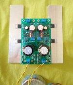
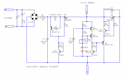
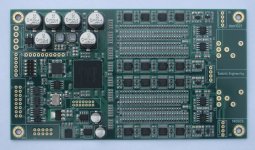
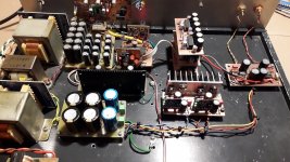
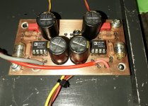
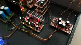
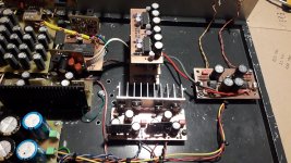
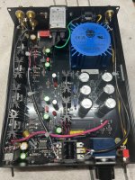
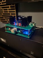
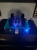
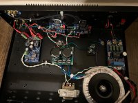
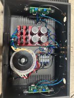
I re-used the flex 8 and some of previous amps at first.
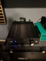
A Schiit rekkr for the horns, perfect, absolutely silent!
A fosi v3 stereo with 36v for the midrange, lowered the volume but it's still a little hissy.
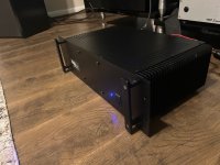
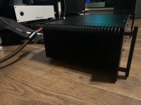
And Crown xls 1502 for the woofers since the boost needs some power.

I initially though about getting some plate amps, fusion maybe for an integrated look, and to get power for the woofers.
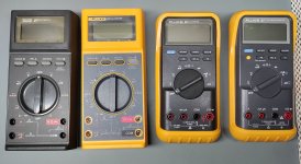
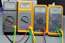
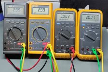
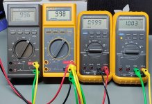
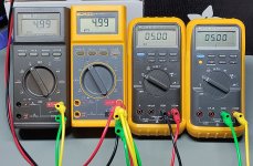
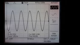
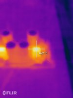
But I also had not so good experience with hypex and HE drivers, so I first took some voltage measurements on the cones to see what kind of power they used.
  • dual parallel woofers, 3.6 ohms at 30hz where EQ boost is severe: at -20db on flex, 2.8 watts and at -10db, where I just almost never go: 28 watts. So far off the Xmax limit around 500w even at max volume.
  • midrange at 1Khz, peak of the response: -20db 0.025 watts, -10db 0.25 watts

Very efficient, so finally and since I don't think I'll ever go over -6db I ordered a second rekkr to put on the midranges, I'm confident they will be then totally silent.
For the woofers the xls is too noisy, tried the little fosi v3 with 48v and it's better, but I think their new v3 mono will be a better match, waiting for them now. Glad I didn't ordered the fusions!


So now I enjoy the new sound, it's different, but the more I tune the closer it gets.
I don't think I will get he clarity of the dipole, but I will just have to decide it I can accept the new compromise.
If ok I will then finish them a little better, paint the baffle, adjust few things, and then start to adapt the room, relocating the diffusors for example.
If convinced I could even rebuild them better, bigger.
One thing for sure, they will be easier to live with as I don't have big powerplants in the middle of the room anymore, better when receiving a bunch of people during summer.
Cats enjoyed them too, they don't care about the cones and I'm glad, just two more big things to climb on and chill 😉

Attachments

  • IMG_3187.JPG
    IMG_3187.JPG
    244.4 KB · Views: 213

For Sale Fully built and working DIY gear.. F5M, LM3886, Pass Front End, H2, Fostex speakers, and Whammy HPA/preamp

Unfortunate work circumstances are forcing me to sell off some of my gear including my work office system since I am losing my office.

Here is a list of everything I have for sale. I can provide more pictures so please ask.

- F5m built into a repurposed Ross Mega 800 amp chassis that was powder coated black. I set it at 1.2A since I used an Antek AS-2218 and it’s the size of a 3U chassis. - Asking $500.

- Nelson Pass Front End Preamp built into a repurposed 1U server chassis. Grayhill switches for power on and input, 3 inputs, and one output, SMPS filter, RK27 Alps volume pot and symphony polypropylene film output caps. - Asking $150.

- H2 Harmonic Generator with XRK simple capmx, low noise TPS7A low noise voltage regulator, and upgraded 10uf film caps built into an Amazon purchased black chassis. Set for 9 DB gain but easy to change resistors for unity gain - Asking $125.

- Whammy headphone amp with 2 inputs, output, Opa2134, and Belden wiring built into an Amazon purchased black chassis - Asking $300.

- LM3886 Integrated amp built into repurposed Bogen chassis with 3 inputs, Antek as-2222, soft start, speaker relay, and modified XY boards with added schematic changes recommended by Tom with Neurochrome. RK27 10k volume pot. - Asking $350.

- Amp camp Preamp and Amp Camp mini combo with two SMPS filter for each unit. All built onto stacked ACP grounding boards. - Asking $400

- Fostex P1000E speakers from Madisound. - SOLD

- Sigma 11 PSU in black Hammond chassis. Triad transformer and set for 24 Volts. Perfect for any of the preamps or headphone amps that take a single rail. - Asking $125

We can discuss shipping costs and for some items I can offer to cover all or half.

Attachments

  • IMG_6707.jpeg
    IMG_6707.jpeg
    196.1 KB · Views: 190
  • IMG_6703.jpeg
    IMG_6703.jpeg
    250.4 KB · Views: 173
  • IMG_6697.jpeg
    IMG_6697.jpeg
    380.3 KB · Views: 168
  • IMG_6688.jpeg
    IMG_6688.jpeg
    213.9 KB · Views: 163
  • IMG_6687.jpeg
    IMG_6687.jpeg
    224.5 KB · Views: 169
  • IMG_6676.jpeg
    IMG_6676.jpeg
    234.1 KB · Views: 176
  • IMG_6675.jpeg
    IMG_6675.jpeg
    173.1 KB · Views: 180
  • IMG_6554.jpeg
    IMG_6554.jpeg
    310.5 KB · Views: 175
  • IMG_6553.jpeg
    IMG_6553.jpeg
    248.1 KB · Views: 184
  • IMG_5408.jpeg
    IMG_5408.jpeg
    710.4 KB · Views: 192
  • IMG_6699.jpeg
    IMG_6699.jpeg
    682.5 KB · Views: 187
  • IMG_6701.jpeg
    IMG_6701.jpeg
    426.1 KB · Views: 182
  • IMG_6503.jpeg
    IMG_6503.jpeg
    1.1 MB · Views: 143
  • Like
Reactions: 6L6

Carbon Nanotube Coating

In the past years, the cost of CNTs has gone down radically while their purity has gone up. CNTs can be expected to far outstrip carbon fiber in their strength to weight ratio. Of course, making a speaker cone out of CNTs (only) directly is not practical because CNTs don't stick together well. However, CNTs are known for as much as doubling the strength of other materials. Common articles assert that only 2-3% CNTs by weight is required for drastic improvements. So I purchased some CNTs that I intend to include in a coating for speaker cones. It was like $75 for 100 grams whereas early on they were more like $50/gram ballparkish. .. clearly enough to do many cones. .. The challenge according to articles is that CNTs don't dissolve like solutes. They have to be dispersed using special solvents and usually stirring and ultrasonics. Otherwise, they clump up and cause more trouble than gain. So I haven't tried this yet, but I think it would be more fun to toss some ideas around. Articles have indicated that multi-wall tubes work better for strengthening other materials so that's what I got. I'm planning on sanding just a little paper off of some paper cones and then replacing with a thinned CNT based coating .. Polyurethane is on the list of possibilities as experiments have been done with it already. So let's see if anyone has any cool ideas about the best way to do this so I can make the best decisions before taking little risks. I intend to do trial runs on useless paper or cardboard.

VA1000 monoblocks with auto-transformer output

A few months ago I have started building new amp and this is going to be another build thread for sharing my progress....

As naming suggests its going to be >1kw amp, design will be similar to the McIntosh 1.25kw amps but majority is going to be designed by myself from scratch.

Amplifier part:
It will be bridged monoblock = two separate amps in one chassis which feeds one common autotransformer with floating output. I have already successfully built this concept in my “MC502” and liked it very much.

Each amplifier is going to be fully balanced classic, nothing new or special. Input diff populated with ONsemi 2n5551/5401, Voltage amp stage uses fast KSA1381/KSC3503 with local compensation to tweak square as needed. As pre-drivers I want to try use Toshibas TTA/TTC004. As drivers classic and powerful MJE15032/33. No need to use anything extra fast here as everything is quite slowed down and compensated to match output transformers anyway. Drivers will feed 8 pairs of MJL1302/3281. Power supply voltage is going to be about 2x65Vdc and each amp will drive approx. 2,7R load.

Schematic:
schema-amp.png

Output stage transistors are split to two separate heatsinks, 4 pairs on each. PCBs are going to be interconnected with locking type IDC ribbon cable which connects main drive as well as temp protection sensor. Bias sensing is only on one PCB done by small to92 transistor sitting flat, directly in the middle of output transistor on top of the package. I plan to stick it there with thermal grease and whole assembly with PCB will force it to sit flat in there. This should provide quite quick and effective thermal sensing and bias tracking.

I have tweaked PCB layout and all the feedback sensing on amps PCBs the best I could to mix all the feedback from both split PCBs + output transformer, well the output terminals - so even the internal wiring is compensated 😉 Power traces are laid on PCB borders around for minimal effect on audio paths, with local low-esr blocking for each output transistor separately. Power and signal grounds are completely separate and going to be connected with separate conduit to main caps, the central ground.
Both PCBs of one amp are mirrored so all NPN/PNP output transistors are going to be on the same side when PCBs are oriented against each-other. This should ease up all the wiring. Below are a few pics of amp pcb:

IMG_9660.jpeg IMG_9662.jpeg IMG_9658.jpeg

(its still work in progress and don't have all the parts yet)

Audio inputs
are on small extra PCB which enables the use of balanced or unbalanced signal similar to mac amps. There is small switch for selecting the input used. As invertor I am planning to use OPA1611 as I feel that one is going to be most neutral of all. I want to make it as good as possible so I incorporated PP audio input caps, to fit them somewhere, they are going to be populated on the bottom side of the board. On this small board there is also small relay for audio mute, which shorts the inputs when amp turns on/off. There is also opto-isolated remote possibility to turn on/off the amp remotely.

This board also basically makes the common audio input ground of the amps (10k), the 100k input resistors directly on amp boards are basically just prevention for cable faulty.
Schematic:
input.png

PCB:
IMG_9669c.jpg
  • Like
Reactions: EdGr and Horneydude

Ambitious direct bias PSE 300B with dual PSU's

It's been 3 or 4 years since this newbie started learning tubes from the wealth of knowledge here. In that time I've been collecting schematics, studying, experimenting, buying parts and tubes that mostly just sit, fun to me but weird to my wife. A few months ago I fell into starting something ambitious, figuring out how I would go about building a direct bias 300B PSE amp with dual PSU's. Inspired by Andrea Ciuffoli, because I kept coming back to his 300B PSE schematic over time. I began with his schematic and dumped every thought I'd need to remember about making one myself onto paper. Simultaneously I've wanted to make dual "boat anchor" PSU's for it, inspired by the Border Patrol amp I really liked at AXPONA. The intention is for the boat anchors to have variable B+, umbilical connected to the amp, so I can re-use the PSU's maybe for a second project. So I'm imitating Andrea Ciuffoli and Border Patrol here but learning. I've attached the schematic as of today, if anyone wants to comment, recommend, help, find errors, etc. Along with the electronics, I'm also doing the mechanical design in 3D CAD as I hope to machine and fabricate the chassis all myself as well. As that gets farther along I'll post 3D models too. Thanks!

Attachments

Driver Recommendations - Bass/Midbass

I have been playing around with designs for a small, thin kitchen system for a while now. I have a few drivers and layouts in mind and I would like everyone's opinion. If there is a large objective difference between these I would love if you'd point them out.

Here is the frequency range I would like to use the midbass units in. The green line.

Shotting for an F3 of 38-48hz. We like bass in our house.
1746234845350.png


Here is a mockup of the design in its location. This location and temporary until we get a new house. Then it will live in the new kitchen. In the new kitchen it will be far more separated. We will not get into the design details of the rest of the system here. Just focus on midbass drivers. I'll make a thread for this build once I get a more concrete idea of what I'm doing.

The narrow baffle is key since they cannot take up a ton of counter space and I want a nice spread of sound. Probably going to be 5-7" dual woofer, 3-4" mid, 3/4" tweeter. Nice spread of sound.

1746234665850.png


Box size will be between 24-50 liters. Quite a spread I know but I could easily make it taller in a MTMWW layout or not as deep to go lower in volume.


I really want to try out dual woofers here. Originally I wanted to use these Dayton 7" drivers and I still might. I feel these are more woofer than midbass though. They are cheap. They have some decent reviews. I can get them for $45 on amazon even though they are out of stock at PE. I would dual these. These are modeled in the mockup above. Aluminum, easy to clean
1746234787142.png

Next up are these currently unobtanium Peerless 5.25" SLS. I have the 8" SLS and I love them. These are 4 ohm so we are looking at series alignment. They are low sensitivity so definitely 2 of them. They would work very well ported and I could get away with a smaller and narrower enclosure. $35 a pop when PE has them, which should be soon. Poly, easy to clean.
1746235018062.png


Another unobtanium. I always wanted a set of these. Should be available soon. Are these more of large mids than they are woofers? I like the fancy motor design, they have incredible reviews. I could use one or two of them. Two would be best with a passive radiator. This, of course, is more expensive than the last two options. $90 each and another $50 for a PR. Paper, hard to clean, maybe not best for the kitchen.
1746235229033.png


I feel these are interesting driver. I know little about Wavecor. They look cheap, they seem overpriced, they apparently measure just as well as scanspeak drivers, they model well, and the distortion graphs have very low distortion right where I want to use these. Cannot validate but read multiple times that the balanced drive is the same technology used in the revelator lineup. Same price as the NE180W. Not as cool looking but if it has better dynamics I am all over it. Would need two. Could also use the 6.5". Paper, but looks super smooth so maybe easy to clean?

1746235438556.png

Definitely need two of these in series. Not sure if these can match the lower dynamics of the other choices. They sim out well enough for the bass I want. Are these more of mid range units? Aluminum, easy to clean. Pretty pricey for a 5" at $80 a pop
1746235564458.png


Pushing the limits of the baffle allotted baffle dimensions we have this Satori unit. The 6" is unavailable. Price point dictates I only use one. Defeats my purpose of trying out multiple woofers. By far the most expensive at nearly $200. Especially for a system that will not get listened to for hours like our other systems. I hear it is only slightly better than the aforementioned Peerless with the similar motor design. Which is a rip off of which?
1746235902416.png


There are a handful of Dayton drivers like the reference series I have also looked at but none of them stand out in any way as far as measurements, price, or reviews. I see no one ever mentioning them as notably special drivers like this collection I have assembled here. If nothing else, I surely do my research.

Let me know if I should be looking at some other driver. Again, midbass dynamic and an F3 of at least 48hz is the goal here. 25-50 liters.

help needed old planar amp receiver

Need help hooking up the main speaker system's remote.
rggl front rggl
rggl back rggl
Caution: floating grounds do not use with common ground system /What does this mean for me, hooking up four speakers?

Next is the main in /pre out front
back main in /pre out

2ch a,b both/4ch a,b and both
How to get them all to play on at once a b and a+b

tape 1___tape2
front and back
play and record
been working on this for weeks, think I got it, then I don't like the way it works, also some speakers don't work on a , b or both some speakers on sometimes, and then on with all
still have to find out how to hook up equalizer and subwoofer if I can to this old Planar XR4120 FOUR/2-channel BRIDGED RECEIVER????
I DO NOT KNOW HOW TO TRANSFER FROM ANDROID CELL TO THIS CHROMEBOOK SO NO PHOTOS UNLESS I CAN SEND TO MAIL OR SOMETHING

  • Locked
YABNOSDAC - Yet Another Boring Non Over Sampling DAC - TDA1541 Throwback project

Folks,

Over in the TDA1541 Meta Thread we had a lot of input to analyse the TDA1541, what makes it tick and how.

https://www.diyaudio.com/community/threads/building-the-ultimate-nos-dac-using-tda1541a.79452/

What I would like to do here is extract the practical part and propose a complete DAC design that may be realised as open source group project.

I would first propose a basic structure.

There will be a main board for the TDA1541 with a super capacitor based "stacked" 20V supply, optimised layout for the various decoupling capacitors needed as discussed in the other thread.

There will be attenuator/slew rate limiter circuits and a set of Flip-Flip's for reclocking and / or division of BCK & LE/WCK as well as a DEM Clock divider from a 512X MCK. The aim is to run a continuous BCK with the lowest frequency possible, so the default option will be I2S with 32X FS BCK, as the lowest sensible without FPGA/CPLD/MCU etc.

There will be embedded clock generation with 22.5792 & 24.576MHz clocks and dividers that allow full slave operation of a frontend at either 32X FS or 16X FS. It will also accept two external 512X MCK from (for example) an SPDIF receiver or USB Board with embedded MCK out that cannot be slave clocked from our on board clocks. Super capacitor based 5V supply.

Space for an analogue stage "plug in" to keep the choice open. My own intention is to use a SuperSziklai Pair based design detailed in the original thread.

Space for a SAA7220 socket that could be filled with an SAA7220 or any PCB holding any FPGA, CPLD, ASRC or whatever. Space will be be left around for a larger PCB to fit this socket. Again, this leaves the choice what goes into this socket (including nothing) to the builder. For my own setup an SRC4190/AD1896 will be fitted to operate as 64X FS to 32X FS I2C converter and as optional dejiiterer for jittery SPDIF Receivers and sources that otherwise sound worse than ASRC engaged.

Anything else will go. Pick your poison. If the 74ACT2226/28 returns from "active but zero stock deads" it may become the FIFO based I2S 2 SIM converter discussed here, otherwise SRC4190 in bypass makes a swell FIFO & format converter with a bonus ASRC):

https://www.diyaudio.com/community/...g-discrete-logic-collaborators-wanted.424459/

Input choices will include standard (Amanero) footprint for USB Boards (mostly XMOS) with isolation via SPDIF (no I2S digital isolators allowed, why will be discussed in good time) and a clock feedback from our crystal clocks with 44.1/48 base selection via opt-isolated pin, probably at least two selectable options.

SPDIF Inputs with SE BNC, XLR AES and Optical plus USB. The SPDIF Receiver position gets a CS8412 DIP socket that accommodate any number of SPDIF RX Solutions, all the way to "roll your own" with FPGA/CPLD/CPU.

I'd draw a block diagram if needed... is it?

So, if anyone is interested in making this a reality as an open source project, join into the discussion.

This is not a channel to debate fundamentals, redebate stuff from other threads or "can you make it into this thing?". If you choose to actively contribute time, effort or money to the project you can of raise suggestions.

I expect to hear crickets, cicadas and the occasional lizard chitering on this thread, but G*d love's a trier.

Thor

PS. As an additional note, all real PCB work will be in Altium, not Kicad or similar educational toys. All simulations and initial schematics capture in TINA-TI. This is non-negotiable.

If you need help with Altium Designer, we can talk in private how to use the free download with full functionality for evaluation and educational purposes beyond the eval time limit. TINA-TI, download at TI.

New to me

Hi all, newbie here.
Interests are tube and vintage SS audio and music gear.
Enjoy HH Scott, Dynaco, Fisher etc on the home audio end.
On the guitar end, I like everything that is point to point or tag board wiring, PC boards not as much.
Really get a big kick out of converting vintage tube PA amps for guitar use.
I build guitar effects for giggles too…
Located in northern Illinois

MF nuVista M3 Refresh

Hi everyone,
I'm a fairly new (second) owner of an MF nuVista m3 amp and was thinking of doing a service on it: a) replacing the old Jamicon electrolytics and, if at all possible, removing any electrolytic caps from coupling duties; b) checking/setting/re-setting the quiescent current on the channels.

With regard to a) there is one 10uF/63V cap that I just can't find a good-sized film cap to replace it C1 and C101 on the attached diagram (Nuvista_M3_Pre-amp_Line_OP[1].pdf). The other coupling caps in the chain (C32, C40, C41 on the right channel) are already some type of film cap, yellow-coloured with a circled L logo--not sure how their quality is honestly--although I'm going to replace them with WIMA MKP10s anyways. Not all that pricey and I'll have it all apart anyways...thank goodness for suppliers like mouser and digikey etc.

Second item, b), does anyone know how "far" I should set quiescent current, i.e. bias into Class A operation? The SAP15's datasheets indicate 40mA, (so 8.8mV across pin 4,5 or 1,2 depending on N or P type), but some manufacturers seem to like "giving it a bit more." Anyone have any thoughts/experience with MF quiescent currents?

Thanks!
verkion
P.S. Attached the whole bunch of M3 Amp diagrams for people's reference. I'll be replacing PSU caps too as those are the ones that are looking "slightly fatigued." i.e. plastic cover is puckering although the metal under it feels fine...for now.

:cop: Copyrighted materials removed by moderation. :cop:

Salas SSLV1.3 UltraBiB shunt regulator

As the beloved SSLV1.1 BiB shunt reg was getting long in the tooth, especially for NOS JFETS, I had in mind for some time now to design its successor. The goals were: 1. In production parts 2. Much simpler to set up. 3. Better technical and subjective performance.

After many breadboard experiments and two prototype PCB iterations I feel that my goals were finally met. So here comes the UltraBiB V1.3 😀

-Uses no NOS parts.
-Can do 5V to 40V output without changing a thing in its parts configuration.
-Nothing to choose and match. No tolerances in predicting its CCS limit setting.
-Has 45dB more open loop gain and many times less output impedance than 1.1
-Sounds easily better.
-Its an electrically and mechanically drop in replacement for an upgrade from 1.1

I have already given spare earlier proto boards with now deleted experimental features to few local beta testers. They are all happy by now as far as I know. The pictured board in green is the final layout in just cheapo proto that's a pain to rework and its pads vaporize in the end. It will come in proper grade black solder mask and immersion gold three sections board just like the original.

Attached: Zout plot for 150ma spare current and noise plots for 100,150,220,330,470,1000uF C2 (red 220uF). Also the rails probed on the scope for positive and negative sections. Here are typical values schematics also. I will write a PDF with instructions. Not that there is something truly special to consider when building it with the suggested parts but to describe it better as an item and to clarify details and precautions.

Updates:
31/5/18 R9's value update
1/6/18 OL sim at 100mA spare
2/6/18 Build Guide PDF added (0V0b)
24/5/19 Triplet board dimensions picture
21/6/19 The PF5102 JFET became EOL. But GB long term supply is secure. For substituting with J113 see info in post #1559
15/5/20 BC560C became EOL. But Group Buy long term supply is secure. BC559 can be used up to 30V output. BC556 for 31V-45V output.
2/7/23 LNA instrumentation measured a very low 2nVrtHz spectral noise density from the UltraBiB under real working conditions. post#3,688

Attachments

  • UltraBiB.jpg
    UltraBiB.jpg
    498.4 KB · Views: 26,807
  • UBZo150mSpare.png
    UBZo150mSpare.png
    14.4 KB · Views: 25,520
  • UBNzC2100-1000.png
    UBNzC2100-1000.png
    15.8 KB · Views: 23,260
  • PSU noise 1us 2mV.png
    PSU noise 1us 2mV.png
    32.3 KB · Views: 25,133
  • UltraBiB-Pos.png
    UltraBiB-Pos.png
    36.3 KB · Views: 27,396
  • UltraBiB-Neg.png
    UltraBiB-Neg.png
    27.2 KB · Views: 16,641
  • OL470R9100mSPR.png
    OL470R9100mSPR.png
    26.2 KB · Views: 12,528
  • UltraBiB_Build_Guide_0V0b.pdf
    UltraBiB_Build_Guide_0V0b.pdf
    556 KB · Views: 11,357
  • UBiB_Triplet_Dimensions.png
    UBiB_Triplet_Dimensions.png
    30.6 KB · Views: 8,559

Fully digital active 4-ways Xover AQ DF75 DUNTECH Sovereign 2001

Six months ago, I bought a second-hand DUNTECH Sovereign 2001 to fulfill a dream from my youth. However, its sound disappointed me, so I decided to modify it. After two months of research, the first step I took was to replace the original DA 30W100 06 subwoofers with Scan 30W/T4558T00, the DA 17W75 06 woofers with Scan 15W/8531K00, and the Scan D2010 tweeters with Scan D2104/71200. Since I couldn’t find an ideal replacement for the midrange drivers, I left them unchanged for now.

The second step was to remove the original passive crossover and install a custom 4-way speaker input panel, moving toward a fully digital 4-way active crossover setup. I'm using the ZIDOO UHD8000 streamer, which allows digital volume control on the SPDIF output, feeding directly into the Accuphase DF-45, then into power amplifier and speakers; no need for preamplifier. This ensures a clean and transparent signal path. The next step is to fine-tune everything using SMAART V8.( I had used SMAART since V3; the Floppy Disc era)

PS: The SCAN drivers for SUB and LOW cannot be directly mounted to the screw holes of the original DA drivers on baffle of Sovereign 2001. Custom-designed and 3D-printed adapter rings are required to fit them onto the existing DA mounting holes on baffle of Sovereign 2001.


Login to view embedded media

Attachments

  • IMG_1345.jpeg
    IMG_1345.jpeg
    392.8 KB · Views: 22
  • IMG_1453.jpeg
    IMG_1453.jpeg
    370.6 KB · Views: 21
  • IMG_1459.jpeg
    IMG_1459.jpeg
    382 KB · Views: 23

New Member – Exploring Summit-Fi and Ready to Learn

I'm excited to join the DIYAudio community! I've been on an intense journey into high-end audio over the past year—diving deep into summit-fi gear like the Mola Mola Tambaqui, Feliks Audio Envy, and RAAL Immanis. I listen primarily through vinyl on a Pro-Ject Debut Carbon EVO, and my digital chain includes components like the WiiM Ultra and RME ADI-2 Pro. My musical tastes range from Pink Floyd and Fleetwood Mac to HVOB, and I'm always chasing that next level of sonic realism.


I joined DIYAudio to connect with others who are passionate about sound, learn more about tweaking gear for peak performance, and maybe even try some DIY builds down the road. Looking forward to exploring and exchanging ideas with all of you!


Cheers

greetings from Cordoba Argentina!

Thank you so much for allowing me to be on this great forum! I've been an electronics technician for several years and also a musician.

I've recently put music aside to focus again on studying electronics and dedicate myself fully to my small lab!

I've always worked with audio repair, but now I'm focusing more on all types of professional and musical audio equipment, as well as some vintage ones.

Greetings and thanks again!

For Sale Power supply for Miro's DACs

Hi,

I have some spare PSUs built for my Miro's PCM63 DAC. Schematic and layout attached.
2 independend sections (separate grounds), transformers for +/-5V or +/-12V outputs, 230V input. Tell me what voltages you need, I'll solder the transformers.
LDOs 7A4701/7A3301, pots for fine adjustment. Caps - Nichicon KZH. I am quite happy with them, no hum and very good PSRR. PCM63 DAC measurements:


So far I have 3 boards for sale, 65 Euro/pc + shipping.
2 black, 1 blue. Size 99x86x30mm
Connectors can be included upon request.

photo_2025-05-03_20-19-36.jpg

Attachments

  • Like
Reactions: zoom777

Lowther A55 alnico

Hello,

Long time...🤓

I’ve built a few Lowther back loaded horns over the years... I am now looking for a design that will suit my A55 drivers. I was looking at the Alerion plans, but it would require substantial mods to fit the fat A55 magnet in there. I was wondering if anyone here has experience building a BACK loaded horn for this specific model (or the A45)?

Any help woud be appreciated.

Thanks.
Dan

WTB Accuton and RAAL speaker

Hello Swap-Meet Community,


Many years ago I designed and built my own passive crossover pairing a RAAL ribbon tweeter with Scanspeak drivers (see my old thread: https://www.diyaudio.com/community/threads/passive-crossover-for-raal-and-scan-speak.227199/). Life intervened —but now I’m ready to dive back in and I’m looking to source the following parts or kits:
  1. RAAL ribbon tweeter
    – Any SR1a / 140-15D models (new or gently used)
  2. Scanspeak top-of-range drivers
    – Beryllium-dome tweeters (e.g. Illuminator series)
    – Revelator midranges / woofers
  3. Accuton ceramic drivers
    – C-series tweeters or high-end ceramic woofers
  4. Passive crossover boards or component kits
    – Specifically configured for RAAL + Scanspeak or RAAL + Accuton combinations
  5. DIY crossover parts
    – Toroids, air-core inductors, film capacitors, resistors, PCBs—ideally matched to the above drivers
If you have any of the above sitting on your shelf, please PM me or if you have full speakers that would be nice too.

Polishing original 1974 KEF vintage speakers

I asked AI. If there's something better please comment below. TIA

Question: Can you recommend good quality brands of wood polish mentioned in the list below for vintage KEF speakers from 1974?
(I live in Portugal, so please only European products)
• 1st. Furniture polish
• 2nd. Scratch remover
• 3rd. Wax stick
• 4th. Wood stain or varnish (for exposed wood)
Important considerations:
• Do not use polishes that contain silicone or excessive oil.
• Although it is most likely a varnish, try to confirm the original finish if possible. This will help you choose the right restoration products.

Answer: Absolutely! Finding quality products in Europe for the restoration of your vintage KEF speakers is perfectly possible. Since you live in Portugal, I will recommend some European brands that generally give good results for the types of products you are looking for.

It is important to note that the availability of specific brands and products may vary by store and region in Portugal. I recommend checking out DIY stores, furniture restoration stores, and some larger drug stores.
Here are some suggestions for European brands in each category:

1. Furniture Polish:
  • Borma Wachs (Italy): This Italian brand is well-known for high-quality wood treatment and finishing products. They offer a wide range of polishes for varnished furniture that are silicone-free. Look for products like “Borma Wachs Polish” or liquid waxes specifically for varnishes.
  • Liberon (UK/France): Although this brand originated in the UK, its products are widely distributed in Europe. Liberon offers excellent wood polishes, including silicone-free options like “Liberon Beeswax Polish” (pure beeswax, which can give a soft shine to varnishes, but test first) or varnish-specific polishes (“Liberon Furniture Polish”).
  • Blanchon (France): Specializing in products for wooden floors and furniture, Blanchon offers good quality polishes to maintain and enhance the shine of varnished surfaces. Check out their range of "Huiles d'entretien" (maintenance oils) or liquid waxes.

2. Scratch Removal Product:
  • Borma Wachs (Italy): Again, Borma Wachs offers products specifically for repairing scratches on varnished wood, such as touch-up crayons ("Retouch Crayons") or fine polishing compounds ("Abrasive Paste for Wood").
  • Liberon (UK/France): Liberon has products such as "Liberon Scratch Remover" which is formulated to disguise superficial scratches on wood finishes, including varnish. * Möbel-Reparatur-Set by Akemi (Germany): Although best known for stone products, Akemi also offers furniture repair kits that include materials for removing scratches from wood and varnish.

3. Wax Filler Sticks:
  • Borma Wachs (Italy): Borma Wachs has a wide selection of “Wax Fillers” in various colors to repair deeper damage and scratches in wood and varnish.
  • Liberon (UK/France): Liberon also offers “Wax Repair Sticks” in various shades to fill chips and scratches in wood furniture.
  • Picard (Germany): Picard is a German brand known for tools and materials for craftsmen, and they offer wood repair wax sticks in various colors.

4. Wood Stain or Dye (for exposed wood):
  • Borma Wachs (Italy): Borma Wachs offers a wide range of wood stains and wood dyes in a variety of colors and shades, ideal for touching up areas where the varnish has been damaged and the wood is exposed.
  • Clou (Germany): Clou is a German brand specializing in varnishes, paints and wood care products, with a good selection of wood stains and paints.
  • Sayerlack (Italy): Although more focused on industrial finishes, Sayerlack also offers high-quality wood stains and paints that can be found in specialty stores.

Important Considerations (to Remember):
  • Confirm the Finish: If possible, try to confirm that the original finish is indeed varnish (which is highly likely for these loudspeakers). You can do this by checking whether the surface is hard, smooth and water-resistant. Varnish usually forms a thicker, shinier layer than wax.
  • Avoid Silicones and Excessive Oils: The brands mentioned above usually offer silicone-free options. When choosing a product, read the description and ingredients carefully to ensure that it does not contain silicone or excessive amounts of oil, as these can interfere with future finishes or attract dust.

Attachments

  • IMG_20250502_162421932.jpg
    IMG_20250502_162421932.jpg
    635.2 KB · Views: 31
  • IMG_20250502_162454108.jpg
    IMG_20250502_162454108.jpg
    705.4 KB · Views: 29
  • IMG_20250502_162604926.jpg
    IMG_20250502_162604926.jpg
    614 KB · Views: 30
  • IMG_20250502_162616994.jpg
    IMG_20250502_162616994.jpg
    419.3 KB · Views: 30
  • IMG_20250502_163257057.jpg
    IMG_20250502_163257057.jpg
    710.1 KB · Views: 32
  • IMG_20250502_163323587.jpg
    IMG_20250502_163323587.jpg
    400.9 KB · Views: 29
  • IMG_20250502_163331841.jpg
    IMG_20250502_163331841.jpg
    502.4 KB · Views: 30

Could use input on a 2.1 boombox

I'd like a big clunky low distortion/ reasonably high spl capable 2.1 boombox centered around my GRS 12PT. A 30 liter 3rd order closed box would do the "point one". I'm looking (if sufficient money comes) at the 16 ohm Eminence Alphalite 6B to reach to 200Hz (again probably cap assisted) plus a tweeter. I know it will be stupid large - perhaps "stupid" period but am having health issues and want to be entertained, It would be run by a $40 Kinter 3118 2.1 amp and a phone. The Kinter has good SQ but its tone controls offer no boost.

A more practical solution due to such close channel spacing with 2.1 in one cabinet would build a MONO boombox.

Here's "1 watt" 2pi for 30 liter with 325uF

1739747797596.png


1739747885817.png


1739747925441.png

1739748019265.png


Alphalite 6B is a 16 ohm driver - helpful to get closer to the woofer's sensitivty. Kinter's "sub" channel says 180Hz lowpass (might be 6dB/oct ?) plus 6B weighs only 1kg. Here's 1.5 liter with a cap.

So with these drivers I'm up to needing 33 liters air-space.

Some sort of tweeter is needed


1739748137968.png

1739748237805.png

1739748448171.png


.

Acoustic Horn Design – The Easy Way (Ath4)

Acoustic Horn Design – The Easy Way (Ath tool)

This is an associated thread for a waveguide generator called Ath (Advanced Transition Horn), version 4.
Ath is a piece of software for designing waveguides and horns. At the same time it makes it possible to easily simulate their acoustic behaviour by means of FEA (BEM) via ABEC/AKABAK tool.

The current Ath release is available at https://at-horns.eu


852187d1591950405-acoustic-horn-design-easy-ath4-render22-jpg


Thread milestones (last edited 26.12.2020, no longer maintained):

#233 Birth of the OS-SE formula
Acoustic Horn Design – The Easy Way (Ath4)

#375 Measuring driver's exit wavefront
Acoustic Horn Design – The Easy Way (Ath4)

#666 Some of the practical verifications:
Acoustic Horn Design – The Easy Way (Ath4)

#844 Ath 4.4.1 - Introducing superformula
Acoustic Horn Design – The Easy Way (Ath4)

#922 JBL M2 "How-to"
Acoustic Horn Design – The Easy Way (Ath4)

#933 JBL M2 - Ath clone
Acoustic Horn Design – The Easy Way (Ath4)

#1003 Comparison of an OS waveguide and a flat piston
Acoustic Horn Design – The Easy Way (Ath4)

#1117 Ath 4.4.3 released (Fusion 360 import)
Acoustic Horn Design – The Easy Way (Ath4)

#1533 Ath 4.5.0 released (scripts not backward compatible)
Acoustic Horn Design – The Easy Way (Ath4)

#1602 General phase-plug discussion
Acoustic Horn Design – The Easy Way (Ath4)

#2389 Joining profiles of different curvatures
Acoustic Horn Design – The Easy Way (Ath4)

#2494 Tritona Waveguide
Acoustic Horn Design – The Easy Way (Ath4)


Spherical-wave phase plug

#1706 Initial ideas
Acoustic Horn Design – The Easy Way (Ath4)

#1824 Kessito's input
Acoustic Horn Design – The Easy Way (Ath4)

#1892 Compression cavity modal analysis
Acoustic Horn Design – The Easy Way (Ath4)

#2016 Diaphragm suspension analysis
Acoustic Horn Design – The Easy Way (Ath4)


Free standing waveguides

#2600
Acoustic Horn Design – The Easy Way (Ath4)

#2936 Rolling back the profile
Acoustic Horn Design – The Easy Way (Ath4)

#3390 Employing axisymmetric BEM (finally)
Acoustic Horn Design – The Easy Way (Ath4)

#3427 Rollback added
Acoustic Horn Design – The Easy Way (Ath4)

#3532 Source amplitude shading
Acoustic Horn Design – The Easy Way (Ath4)

#3549 OS-SE formula extended: k
Acoustic Horn Design – The Easy Way (Ath4)

#3664 Effect of an enclosure and other parameters
Acoustic Horn Design – The Easy Way (Ath4)

#3822 Compression driver throat plug
Acoustic Horn Design – The Easy Way (Ath4)

#4186 Preferred in-room response and DI target (discussion)
Acoustic Horn Design – The Easy Way (Ath4)

#4503 Incorporating compression driver model
Acoustic Horn Design – The Easy Way (Ath4)

Attachments

  • ath4_UserGuide.png
    ath4_UserGuide.png
    138.5 KB · Views: 16,757

LJM L20 V9.0 Amplifier

Hi all,
I got two of these kits off ebay http://www.ebay.com

It all came very well packaged, and everything was there, except for a cap, which was the wrong value (220/63v instead of 150/80v). No big deal, i changed them all to 220/80v just for the heck of it. The PCBs look very robust and very well made, they're thick and heavy, almost glass like! They are, alone, totally worth the money. The output transistors (KEC D1047/B817) don't inspire a lot of confidence, but they should be ok for domestic music.

I assembled the kits and hooked them up to a 33v-0-33v beefy power supply for some testing. Both kits seem to work ok, and they sound just fine. I tried a 4Ω/100w sub woofer, and it quickly reached it's xmax. The heatsinks got warm after 2 minutes, but not hot...

Now the problem is, despite the good sound, i can measure no bias current at the outputs. The heatsinks are cold as beer even after an hour of being turned on with no signal at the input. I used 10Ω power resistors at each rail, and i calculated an idle current of about 13-14mA per rail, per amp module. It seems very low😕.

With inputs shorted, the emitter resistors (0.15Ω) all measure dead zero mV (0.0). The voltage across R26(200Ω) is about 850mV. I think thats about half the optimal voltage to even begin conduction at the output transistors.

What baffles me, is that the amp sounds just right with no apparent output bias. Even the top end sounds smooth, no signs of being grainy or harsh at all. Is that normal?

Could it be that the rail voltage is rather low? The optimal voltage per rail, according to the designer, is around 65v. I will test again with the power supply which i intend to use permanently (57v rails). I hope the higher dc voltage will affect the, almost non existing, standing current.

Here is a (not very revealing) schematic i lifted from another thread. I haven't checked for errors, but it seems close enough.

Attachments

  • ljm l20 v9.jpg
    ljm l20 v9.jpg
    609.7 KB · Views: 3,384

QUAD ESL-63 panel without stator PCB

There is a recently applied patent that takes another very different look at making an electrostatic loudspeaker. Particularly the way the stators are made.
I contacted the patent holder and asked if it was OK to give a DIY approach on his design a go. As long as I was not promoting it commercially he was OK with it.

So here is a short video of the very open design as a proof of concept. Yes it works and it works fine.
Sensitivity is very acceptable, distortion is low, but what is most remarkable and I don't know of any way of measuring that, is how OPEN is sounds. That was also most likely the intention of the design in the first place.
The designer claims a complete break on the relation between open area and capacitance, but that is, sorry to say, not true. There is a fixed relation between the two, but obstructions area is much smaller than with wire or PCB stators.

Took several days of 3D printing the 500+ parts that are in there and several weeks of manual labour to apply and assemble the whole contraption.

Per panel the square space is like a Quad ESL-63 panel. Eventually we want to try and build a complete speaker with 4 of these panels each. The ultimate goal would be to apply the delay rings as well.

Panel size Mylar surface 58x17 cm. That is 98.600 mm2 of surface area.
Obstruction surface is only 18.300 mm2, only 18,5%.
Open surface remaining is a whopping .... well you can see it in the short video.
Stator to stator capacitance is 90 pF.
Diaphragm movement space twice 2,5 mm (also like the Quad-63 panel)

Please note that this is a patented design and done here just for the fun of proving that it can be made with simple means and to have a listen at the characteristics without having to travel half the world to hear the original concept. There are still a lot of thoughts on how to change/improve upon what is demonstrated here.

  • Like
Reactions: Daihedz

Folded Horn Acoustic Guitar Patent # 10,777,172

Hello all - I am new to this site, looks really great! I was granted a 20 year Utility Patent last year for my Folded Horn Acoustic Guitar. Patent # 10,777,172, can find on Google Patents of course. I have two five foot long folded horns inside an acoustic guitar. The horn is exponential and has a 1:8 ratio from throat to horn, with a speaker mounted to each compression chamber. This is long enough to capture the lowest frequency on an acoustic guitar at 1/4 wavelength. The true acoustic sound is a captured by a mic, not a pickup. Check it out and let me know what you think. CNC programming is complete, and will build a partial proto next week. Thanks!

ZOTL and ferrites

US patent 5,612,646 (PDF version) discusses Berning's ZOTL circuitry (there are actually commercial amplifiers), where instead of using a regular output transformer, the output tube is fed through a high frequency ferrite transformer by the load and MOSFET bridge. Begning claims significant improvements in performance as the high frequency transformer supposedly has little impact on audio frequencies (the switching frequency is suggested around 250 kHz).

A diyaudio member, hifizen, suggested to me that a better design would, instead of having a switching bridge in the signal path, use AM modulation, thus still allowing the use of a high frequency transformer instead of a regular OTL.

I'd like to get some opinions and discussion on the pros and cons of these two suggestions, as well as implementation caveats to watch out for (I actually intend to build one or the other, and have procured appropriate ferrite cores).

Reference DAC Module - Discrete R-2R Sign Magnitude 24 bit 384 KHz

I have been working on a little side project, now it's time to present it for everybody here....

It's a DAC module based on a discrete R-2R sign magnitude DAC design, with FPGA based reclocking and custom digital filters, < 1 ps jitter clock generator, with 28 bit resolution so there is headroom, oversampling up to maybe 3.072 Mhz. Up to 24 bit / 384 Khz input from SPDIF, I2S and USB (via USB to I2S interface board), with isolation on the I2S interface. The board will be very flexible, with digital volume control and filter parameters that can be downloaded, a possibility is also to add digital crossover filters, but that will probably not be ready for first production lots, although the board is firmware upgradable over a simple serial connection.

The basis R-2R network has an output voltage of 1.4V RMS and output impedance of 625 ohm and can therefore drive a lot of things directly.... There is also onboard balanced output drivers that can drive high impedance (>= 300 ohm) headphones directly. The power supply is also onboard, just add a 5W toroid transformer.

It is a small mostly surface mount PCB, and yes, I have working prototypes, see below.... But it's not really something for home assembly, with the FPGA in BGA package and 600 pcs SMT parts.... So yes, if there is enough interest it will go into real production, with sales though two existing online shops in US and EU.

Performance of first prototypes using 0.05% resistors is better than expected, see 1 Khz -1 db and -60 db FFT plots. I believe that the sound quality will be the absolute best, better than any Delta Sigma DAC, in class with discrete DAC's from totaldac and msb technology. And for way way less cost 🙂

----

Update on Apr 26, 2021:

dam1021 rev 7 is now released, see post# 10146, Reference DAC Module - Discrete R-2R Sign Magnitude 24 bit 384 Khz for details.

Update on Apr 29, 2018:

Vers. 1.19 firmware with with filters now available on Soekris Engineering ApS, R-2R Sign Magnitude Audio DAC
The dam1021 have been shipping as rev 5 for a while, but no major updates, just production related updates.

Update on Oct 14,2016:

The dam1021-12 and -05 are in stock again, still rev 4.

Update on May 27, 2016:

Vers. 1.06 firmware with DSD support now available on Soekris Engineering ApS, R-2R Sign Magnitude Audio DAC

Boards from next production run will be rev 4 and are now in stock, that batch will only be the 0.05% and 0.01%/0.02% resistor version, which will be the only two dam1021 versions available long term. The only other change from rev3 to rev4 is a change in the output buffers, the LME49710/LME49724 is replaced with OPA1602.

Pricing for board rev 4 is:

dam1021-12: USD 295 / EUR 266 (0.01%/0.02% resistor version, in stock)
dam1021-05: USD 195 / EUR 176 (0.05% resistor version, in stock)

Pricing for board rev 3 is:

dam1021-02: USD 265 / EUR 238 (0.02% resistor version, very low stock)
dam1021-05: USD 195 / EUR 176 (0.05% resistor version, sold out)


Shipping cost and any sales tax and/or other local taxes to be added.

They are available to order though two existing webshop:

404 Not Found for American and Asia markets.
Soekris Europe » for EU and European markets.

The main Soekris Engineering ApS (Denmark) website for product and technical information is:

Soekris Engineering ApS, R-2R Sign Magnitude Audio DAC Please don't email soekris.com or soekris.eu with technical questions....

See also post #901 http://www.diyaudio.com/forums/vend...-magnitude-24-bit-384-khz-91.html#post4197094 for a quick drawing with connections.
And post #1108 http://www.diyaudio.com/forums/vend...magnitude-24-bit-384-khz-111.html#post4202602 for SPDIF interface drawing.
And great info here https://hifiduino.wordpress.com/2015/01/30/building-soekris-r-2r-dac/
Post #1486 http://www.diyaudio.com/forums/vend...magnitude-24-bit-384-khz-149.html#post4216998 with filter tools.
Post #3276 http://www.diyaudio.com/forums/vend...magnitude-24-bit-384-khz-328.html#post4421518 Firmware revision 0.99 update
Post #3295 http://www.diyaudio.com/forums/vend...magnitude-24-bit-384-khz-330.html#post4421780 more info on 0.99
Post #3108 http://www.diyaudio.com/forums/vend...magnitude-24-bit-384-khz-311.html#post4392832 Official vref modification
Post #3362 http://www.diyaudio.com/forums/vend...magnitude-24-bit-384-khz-337.html#post4425324 More info on vref mods

Anybody can now order the dam1021 R-2R DAC board from the two webshops.

Attachments

  • dam1021_top.jpg
    dam1021_top.jpg
    536.4 KB · Views: 47,990
  • fft_-1db.jpg
    fft_-1db.jpg
    172.3 KB · Views: 43,559
  • fft_-60db.jpg
    fft_-60db.jpg
    161.4 KB · Views: 41,158

How best to use a Lowther A45? for a mono speaker

I'm looking for advice on a mono speaker design for a small room.

A couple of years ago I had an idea of building a big Tractrix front loaded horn (FLH) and large mid-bass horn to go with - for a single mono speaker, i.e. a large 2-way (at the time inspired by Tune Audio). The mids driver used by Tune Audio is a modified Fostex 126 but I decided for some reason now lost in the mist of time to buy a Lowther A45 driver. I didn't proceed very far with this idea once I realized that I don't have a large enough room for such a beast and that the work effort involved was just too much for me to take on when I have other demands on my time. So I have this Lowther A45 just sitting around and I'm not sure what is the best way to put it to use. I'm interested in some suggestions from the forum members ?

To keep this simple I'm OK accepting some compromises in terms of the performance in order to limit the size and complexity so that I can build something without it taking months of effort. I'd also like to be able to deploy the speaker in a smaller room where it can provide a more intimate listening experience, partnered up with a tube amplifier.

1/ The driver is not really suitable for baffle mounted use due to the rising treble response (see attached datasheet). So, right off the bat I expect I'll need to address that limitation. One option is to shape the frequency response of the driving signal, either a filter network at the driver, or at line-level. The other option is to shape it physically by employing a small front horn, something designed to help flatten the frequency response rather than provide directional control - I'd actually like wide dispersion if possible.

2/ The driver is not really suitable for generating bass, it's got limited cone area and limited x-max. I guess it's good down to 200Hz to 300Hz at moderate listening levels suitable for a small room. Other than accepting limited low frequency output the only option would be to add a supporting woofer.

So with my limited experience I have been thinking about
a) Open Baffle with small front-horn on the Lowther and with the woofer needing real power it would have to be a bi-amp set-up,
b) A modest compound horn, i.e. a back loaded horn (e.g. Lowther Alerion for which I do have the plans) perhaps with a small front-horn on the Lowther. A separate sub is possible. What about a double mouthed horn - worth the extra wood ?

So as you can see, I've given this some thought already but I've so little experience of these things.

Your thoughts ?

Attachments

  • A45_Front.jpg
    A45_Front.jpg
    11.6 KB · Views: 103
  • A45_Rear.jpg
    A45_Rear.jpg
    13.3 KB · Views: 108
  • Lowther A45 datasheet.jpg
    Lowther A45 datasheet.jpg
    145.4 KB · Views: 117
  • alerion.jpg
    alerion.jpg
    20.5 KB · Views: 116
  • maxresdefault.jpg
    maxresdefault.jpg
    61.5 KB · Views: 97
  • 9.jpg
    9.jpg
    23.7 KB · Views: 111

USSA-5 Build with Review

USSA-5 build and review:

Amplifier Design/layout: Fab (The Great and Powerful Ape)

Amplifer PCB Layout: Alex

PSU Design/Layout: Project16

PSU PCB Production: Prasi


I couldn't stop thinking about this amplifier. The obsession began with a few fleeting traces of it's existence. The few members that have actually completed it were mostly silenced by its greatness. When I had enquired about it, people simply said "Oh, the USSA-5? It's the best amp I've ever heard."

I had to build it. But, the great mind that designed the amp wasn't going to just give me the boards. I offered to build a children's wing at his nearest hospital in his name. He said no. I said I would make huge donations to wildlife preserves around the world. He still said no. He was like talking to Willy Wonka and I was Charlie Bucket. I needed a golden ticket....

In the end, what worked was honesty and a promise to do two things: to build the amplifier and write a review.

So, here it is.

For Sale bundle of two Soekris R2R DAC board with many kits | Dayton audio woofers and microphone

Last of my DIY parts

Bundle of Soekris two R2R DAC boards with many kits and accessories
this bundle includes:
1 - Soekris DAM 1021-02
This is new and tested confirmed working 100%. comes in original box from soekris with molex connectors, the USB cable to pragram the firmware and Neutrik XLR connectors are new and perfect. these are the pictures: Login to view embedded media
2 - Soekris DAM 1021-01
this is the one that is installed in the box. i have used this for coax and usb input a lot and sounded glorious. pictures below

3 - AMANERO USB ITS INSTALLED IN THE BOX,. pictures below

4 - AZ OLED lite Green color
this is perfect and tested. it is installed in the box. picrues below.

5 - Normundss kit for soekris 1021
here are the pictures:


6- the aluminum box with vu meters. this is an awesome box and i prefer to keeep it. it is complete and i have all parts and will be included


Things that i still have for sale: Login to view embedded media
1 - the linear power supply has really good and expensive and like new capacitors. the transformer is antek As 0509. this is free if you buy everything.

2 - Dayton audio 6.5 inch designer series woofer. quantity = 3. two are tested and like new and have solder residue. one is new. https://www.parts-express.com/Dayton-Audio-DS175-8-6-1-2-Designer-Series-Woofer-295-428?quantity=1

3 - Dayton measurement mic with calibration gragh. new https://www.parts-express.com/Dayto...1Qb6g07lZP4sLsTooJmKa1ABDgWreSYcaAtHpEALw_wcB

4 - pair of peerless tweeters NEW
https://www.parts-express.com/Peerl...50U221j7tfuh5fhWG-HswPDSEVg4XRFAaAo4GEALw_wcB

all together $155 paypal friends and family
weight is almost 20 pounds for the whole thing

For Sale Fluke Multimeters (EU): 27, 27FM, 85, 87

Selling some "vintage" multimeters.

The legendary Fluke 27/27FM were made for demanding environments: rugged, 1m waterproof, quite bulky and heavy and with an incredibly long battery life. Not easy to find on this side of the pond.

The Fluke 85/87 are first-series models. I guess no introduction needed.

I tested them at 300mV DC, 3V DC, 5V DC, and 1V AC. I forgot the resistance test, but I can do it later this week. I have never used the current measurement.

Price list:
27 – 95 EUR
27FM – 115 EUR
85 – 130 EUR
87 – 160 EUR

If you buy a pair, we can share the shipping cost. If you take all four, I will cover the shipping.

PayPal in EUR via Friends & Family or + PayPal fee.

Attachments

  • 2025-03-23 15.19.53.jpg
    2025-03-23 15.19.53.jpg
    494.6 KB · Views: 170
  • 2025-03-23 15.20.41.jpg
    2025-03-23 15.20.41.jpg
    335.9 KB · Views: 125
  • 2025-03-23 15.21.30.jpg
    2025-03-23 15.21.30.jpg
    297.6 KB · Views: 92
  • 2025-03-23 15.23.12.jpg
    2025-03-23 15.23.12.jpg
    246.5 KB · Views: 100
  • 2025-03-23 15.27.26.jpg
    2025-03-23 15.27.26.jpg
    510.8 KB · Views: 108
  • 2025-03-23 15.28.05.jpg
    2025-03-23 15.28.05.jpg
    519.4 KB · Views: 117
  • 2025-03-23 15.29.24.jpg
    2025-03-23 15.29.24.jpg
    525.1 KB · Views: 117
  • 2025-03-23 15.30.28.jpg
    2025-03-23 15.30.28.jpg
    557.8 KB · Views: 103
  • 2025-03-23 15.18.44.jpg
    2025-03-23 15.18.44.jpg
    330.1 KB · Views: 137

Sunvalley SV-S1645 - 45 Tube Amp - Available NOW

Here is the info for the 45 amplifer from Sunvalley - SV-S1645D​

The composition of the vacuum tubes:

12AT7 x1 or 12AX7

12AU7 X 2

45 X 2

274B/5U4G (tube rectifier only)

Output transformer Hashimoto H20-7U.​

Choke and Power Transformer 115/230V custom made​

Made and Assembled by Sunvalley Japan with 4 x VCAP ODAM (0.1 X 2 + 0.22 X 2)​

Available in February 2024 - Only 25 units for the 1st production​

Price : $2,725 ( included development fee $250 per unit charged by Sunvalley)​


1689218341650.png


[


[URL='https://flic.kr/p/2oPzp7X']


52701032247_c1a2d5fe0d_h.jpg
[/URL]

WE expect it will take 8-9 months to complete the following processes. Please stay tuned....
  1. Circuit approval - DONE
  2. Prototype production - DONE
  3. Prototype Evaluation - DONE
  4. Prototype approval - DONE
  5. Quote Approval - DONE
  6. Mass production - WIP
  7. Assembly _ Sept 2023
  8. Characteristics Verification
  9. Shipping jAN 2024
  10. SCHEDULE ARRIVED Vancouver Feb 24, 2024

AD811 as I/V stage for current DACs (and test some other opamps including Burson Audio opamps as I/V)

First, let me introduce my DAC, some have already seen it, but for those who haven't, it's a classic old-school DAC with DIR9001 as a digital receiver, PMD100 digital filter and 6 PCM1702s, three in parallel for each channel. The output current of 3 PCM1702s is 7.2mAp-p max. The power supply is given the greatest care, the PCB itself with DIR9001 has three ADP7118 regulators and they are the only IC reg. in the DAC. Other regulators, two +5V for PMD100, +/-5V for PCM1702 and the new +/-10V for AD811 are low noise shunt regulators, slightly improved, made according to Mr.Walt Jung's article and with the help of Mr. Walt. These regulators proved to be much better than the best IC reg ADM7150. There are three transformers to completely separate the power supplies of the digital and analog sections. The rectifiers use CRCRC filters to reduce the ripple as much as possible before the regulators themselves.

And now a little about AD811. AD811 is a high performance video and current feedback operational amplifier with 2500 V/μs. I used it for the first time about 15 years ago with a TDA1541 and two PCM1702, later I switched to tubes, but I wanted to give the AD811 a chance again because I think it deserves it.
The scheme is from Walt Jung from 2/92, published in Audio Amateur, and that's how I connected the AD811 for the first time with op.amp nad filter after AD811. The difference is that now after AD811 there is nothing, the signal goes straight to the amplifier without any additional op amp and capacitor on the signal path. Between AD811 and Le Monstre amp is only the P&G 10K sliding pot.
For this reason, a higher output signal of 3.34Vrms (9.52Vp-p) was chosen, and since the AD811 can provide 100mA at its output, there are no problems with driving the any amplifier at all.
The scheme of the I/V stage itself is simple, the only difference between the classic I/V is in the resistor R1 in front of the inverting input. The output voltage is simply calculated by the formula Vout=-Idac*R2.
The only audio filter(first pole) is R1/C1 and depending on the selected capacitor it ranges from ~40kHz for 2.7nF to ~49kHz for 2.2nF and it is calculated according to the formula fc=1/(2*pi*R1*C1) .
The size of the PCB is 42x80mm. All resistors are RN60 with 100uF/50V UKZ+ 10nF COG SMD for decoupling. The AD811 is an HF beast and should be treated as such. Small capacitors(C1,C5) can be polystyrene, mica or polypropylene.
The supply voltage of +/-10V was deliberately chosen that way because of the heating of the AD811 itself, if a small heatsink is placed on them, supply voltage can be higher.
The story continues 🙂

Attachments

  • ad811 sch..png
    ad811 sch..png
    20.6 KB · Views: 2,611
  • grunf dac.jpg
    grunf dac.jpg
    477.8 KB · Views: 2,228
  • ad811 2.jpg
    ad811 2.jpg
    517.9 KB · Views: 1,463
  • AD811 1.jpg
    AD811 1.jpg
    580.1 KB · Views: 1,329
  • AD811 out volt..jpg
    AD811 out volt..jpg
    342.8 KB · Views: 1,205
  • AD811 temp..jpg
    AD811 temp..jpg
    81.3 KB · Views: 1,156
  • grunf dac 3.jpg
    grunf dac 3.jpg
    404.6 KB · Views: 2,149

Roederstein Draloric 0.60w resistor

Roederstein draloric 0.60w resistor

Attachments

  • IMG_20250430_232911.jpg
    IMG_20250430_232911.jpg
    154.3 KB · Views: 23
  • IMG_20250430_231823.jpg
    IMG_20250430_231823.jpg
    140.8 KB · Views: 19
  • IMG_20250430_231415.jpg
    IMG_20250430_231415.jpg
    119.8 KB · Views: 17
  • IMG_20250430_230937.jpg
    IMG_20250430_230937.jpg
    240.7 KB · Views: 17
  • IMG_20250430_230539.jpg
    IMG_20250430_230539.jpg
    109.6 KB · Views: 17
  • IMG_20250430_230140.jpg
    IMG_20250430_230140.jpg
    226 KB · Views: 18
  • IMG_20250430_225800.jpg
    IMG_20250430_225800.jpg
    117.4 KB · Views: 16
  • IMG_20250430_224934.jpg
    IMG_20250430_224934.jpg
    107.3 KB · Views: 17
  • IMG_20250430_224548.jpg
    IMG_20250430_224548.jpg
    117.7 KB · Views: 17
  • IMG_20250430_224129.jpg
    IMG_20250430_224129.jpg
    117.4 KB · Views: 16
  • IMG_20250430_223526.jpg
    IMG_20250430_223526.jpg
    112.2 KB · Views: 17
  • IMG_20250430_223009.jpg
    IMG_20250430_223009.jpg
    109.1 KB · Views: 13
  • IMG_20250430_222701.jpg
    IMG_20250430_222701.jpg
    107.3 KB · Views: 12
  • IMG_20250430_222102.jpg
    IMG_20250430_222102.jpg
    106.4 KB · Views: 13
  • IMG_20250430_221808.jpg
    IMG_20250430_221808.jpg
    257.9 KB · Views: 13
  • IMG_20250430_221204.jpg
    IMG_20250430_221204.jpg
    108.3 KB · Views: 12
  • IMG_20250430_220858.jpg
    IMG_20250430_220858.jpg
    105.5 KB · Views: 10
  • IMG_20250430_220505.jpg
    IMG_20250430_220505.jpg
    118.1 KB · Views: 13
  • IMG_20250430_220053.jpg
    IMG_20250430_220053.jpg
    113.6 KB · Views: 10
  • Screenshot_2025-04-30-21-57-33-285_com.miui.gallery.jpg
    Screenshot_2025-04-30-21-57-33-285_com.miui.gallery.jpg
    100.3 KB · Views: 21
  • Like
Reactions: Fran008

DIY speakers based on Dunlavy speakers.

I heard these speakers by someone who tried to build Dunlavy SC V1 clone type speakers. They used two Focal Audiom 15 inch woofers. The model number for the woofers were 15VX. These were top of the line Focal Audio 15 inch woofers, 2 Focal Polyglass midbases. The model number for the midbase was 7K6411 and a Raven R2 ribbon tweeter.
The speakers were about 6 feet tall and weighed 335 pounds.

They speakers had a nice soundstage and the bass was tight with good extension. These woofers were very impressive.
Now, he couldn't do a crossover like Dunlavy. Dunlavy could make speakers that used ok drivers, but make the speakers sound great.

I remember i heard the Dunlavy SC-IV speakers that used all Vifa drivers. These speakers had an amazing soundstage and sounded very layered and the bass was fast and tight. I always though what could Dunlavy have designed using top of the line drivers like Focal at the time or Scanspeak.

Here's a pic of the speakers he designed.
1746193658421.png

"Mechano22" - a small 2-way speakers with linear on-axis and power response characteristics

(For Mechano24 design with Scan Speak drivers click here LINK)
(For Mechano323 3-way design with AMT driver click here LINK)
(For Mechano23 design with Scan Speak and SB Acoustics drivers click here LINK)
(For Mechano325 7l 3-way design with Dayton drivers in "horizontal" arrangement click here LINK)


Mechano22
Not so long ago, I made a small 2-way speaker design with the following goals: f6 around 40Hz with 8 liters BR enclosure, generally balanced on-axis response and close to linear frequency power response.

Experience gathered with that design led me to a conclusion that maybe it could be done better and cheaper. And here is the new version, codemame "Mechano22".

It is based on relatively inexpensive set from Dayton: ND25FW-4 tweeter with waveguide and DS135-8 midwoofer.

Box dimensions: HxWxD: 290x174x260mm, made of 18mm birch plywood. The Box is filled with polyester fiber.

Both drivers are placed in the middle of the front panel, with centers 75mm (tweeter ) and 195mm (woofer ) from the top edge.

The woofer has a flat basket edge, which, according to the manufacturer's note, allows application without flush so it wasn't implemented. On the other hand, woofer mounting hole was chamfered on the inside.

Pic1. System on-axis and power response characteristics in comparison with target lines. For power response calculation +-180deg measurements were taken in H and V planes (10deg step):
m22onaxisPwrresp.png


Pic2. frequency response for DS135-8 (orange) and ND25FW-4 (gray):
drivers_mech22.png


Pic3. Crossover schematic:
sch22.jpg


Pic4. VituixCad, schematic and 6-pack for double check:
6p22.jpg


Pic5. Filters assembled on a scrap of plywood (for 1 unit):
zmontowanaZwrotnica.png


Pic6. Units assembled (need sanding and waxing ):
zmontowanie monitory.png


Pic7. Measured on-axis dBspl (both units, 5dB/div). f6=40Hz if I did not messed up the measurements.
sysRespOnAxis.png


Pic8. Measured system impedance (both units).Nominal impedance is 6R (considering 5R minimum at 200Hz):
sysImped.png


List of components used (for one unit):

Dayton Audio DMPC4.3 / 4.3 uF / 5% / 250 V / Polypropylene capacitor MKP
Capacitor Jantzen Audio CrossCap 0.47uF / 400VDC / 5% / MKP /
Dayton Audio DMPC8.2 / 8.2 uF / 5% / 250 V / MKP 2 pcs.
Capacitor Jantzen Audio Cross-Cap 9.1uF / 400VDC / 5% / MKP
Dayton Audio DMPC-2.7 / 2.7 uF / 5% / 250 V / MKP polypropylene capacitor /
Ty-Ohm ceramic resistor 22ohm / 22R0 / 20W 5% SQP
Ty-Ohm ceramic resistor 4.7ohm / 4R7 / 5W 5% SQP
Ty-Ohm ceramic resistor 100ohm / 100R0 / 5W 5% SQP
Ty-Ohm 12ohm / 12R0 / 5W 5% SQP
Jantzen Audio core coil 0.68mH / cylindrical / 0.162ohm / dr.1mm Fe 0.021kg / dia.20, length 40mm /
Jantzen Audio core coil 0.82mH / reel / 0.22ohm / dr 0.8mm Fe 0.056kg / dia.24 length 33mm /
Jantzen Audio Air coil 3.7mH / 3.25ohm / dr 0.5mm / dia.33, length 15mm
Jantzen Audio Air coil 2mH / 3.21ohm / dr 0.4mm / dia.31, length 8mm
Jantzen Audio air coil 0.12mH / 0.26ohm / dr 0.7mm / dia.27 length 8mm

Attached files: VituixCAD *.vxp and XMachina *.xmp with spinorama.

Attachments

Elektor Preamplifier 2012 new personnal project

Hello all,

I am working on my DIY Preamplifier new project based on the Elektor Preamplifier 2012 (Douglas Self) schematic.

I don't need the TONE and BALANCE control sections in my design, painted in Red in the picture below. I will directly connect the output of IC2A pin 1 into the input of IC9B pin 5 (Green traces).

Still I have this question regarding the filters in the input of IC2A pin 2 and 3, painted in Yellow. Do I need them or they are part of the BALANCE section only?

And if needed, should I replicated the R11-R12-C6 filter with R8-R9-C5 connected to ground?

Thank in advance 🙂

Elektor_modifiée.png

Hello music lovers

I'm new here. I thought that some of you might be interested to know that while I love audio equipment and listening to great music, I am a professional musician...a violinist. I am the lead violin with the Fox Theater in St. Louis and I played in the Saint Louis Symphony Orchestra for 20 years. Very few of my colleagues have high quality systems and sit down to listen as I do. Perhaps performing is enough for them.

Adrian

Power Supply with Active Rectifier, RF Filter and Super-Regulator

This single rail power supply is an improvement over R21 power supply add-on module. It has an active rectifier, RF filter and super-regulator on a single compact PCB (120 x 70 mm). Performance is comparable to R21, except for the PSRR at high frequency, where this new supply maintains > 60 dB PSRR far into MHz range. It doesn’t have, for now, negative voltage counterpart.

It works, as is without any changes, from 10 to 60 V output voltage for a version without RF filter. Max. output voltage for a version with RF filter is 50V. Output current is up to 10 A (20 A short term), with dropout voltage of 0.15 V for 10 A load. Headroom voltage for 10 A load is 0.5V.

PSRR is greater than 110 dB @ 100/120 Hz and supply self noise is about 2 µV.

Twins2.jpg


Measured performance:
  • 110 dB PSRR @ 100/120 Hz at 0.3 V headroom and 2 A load
  • 2 µV total noise @ 2 A DC load or 15 nV/rtHz noise density
  • 0.002% load regulation @ ΔI = 5 A (< 0.5 mV output voltage change for the 5 A load increase at 25 V output)
  • 0.00008 %/V line regulation @ ΔV = 30 V (< 0.5 mV output voltage change for the 30 V input voltage rise at 25 V output)
  • 1.4 mΩ output impedance @ 20 kHz (including output PCB tracks resistance!)
PCB
1 oz copper is fine for dynamic loads up to 10A. For max performance and high current capability, 2 oz is better. All measurements were taken on 2 oz PCB version. Take a note that it may be cheaper to order 2 oz + ENIG finish PCB than just 2 oz and standard finish one, at least when JLCPCB is in question. It depends on other orders in the momentary queue, so you’ll have to check.

Parts
Worst shortages are behind us and I tried to reduce number of different semiconductors anyway. Everything is available but main heatsink is available in limited quantity. I may need to find another one soon.
C2 should be, depending on required voltage, biggest capacitance type that physically fits the PCB. Diameter up to 40 mm is OK. In the BOM, I’ve put the biggest available with 63 V rating.
For output voltages up to 30V, use at least 33.000 – 47.000 uF capacitors. Rule of thumb is that to have max.1 Vpp ripple at the voltage regulator input, we need 10.000 uF per every A of output current. As less input ripple is better, using large capacitors is better.

At 50-60 V output voltages, it would be good to replace R8 & R9 with 4K7 & 3K9 values, to avoid high dissipation and temperature.
More details about required changes at 50-60V output are at posts #245 and #246.
For output terminals, Fast-On connectors or terminal blocks with 5 mm, 5.04 mm or 6.3 mm pitch can be used.

Shared Mouser cart for one click order:
https://hr.mouser.com/ProjectManager/ProjectDetail.aspx?AccessID=b48c6947bd

Building
Proposed assembling order from the R21 build guide still applies in general. Add parts by height order, starting with diodes. However, as there are several more SMD parts, best method would be to put all SMD components first, except opamp, and then proceed with TH components. All SMD components are situated on the PCB B side. Place opamp as last or after most TH components surrounding it, has been soldered.
Murata RF filter is part to be mandatory soldered by hand. Don’t try to use hot air tools! Upper cover will melt. How do I know? 🙂
Common Q7/Q8 heatsink is required only above 30V output. At 50-60 V output, you can attach token heatsinks to Q5 & Q6 as well.
I’ve build 3 samples for verification purpose, so everything should work reliably.

Start-up behavior
Contrary to the R21 module, which was designed to ignore any amount of capacitance downstream, this regulator is not designed with driving capacitors bank weighting 10 kg in mind. Though, any decoupling capacitance in powered circuits is fine. This enabled to have regulation from the start and output voltage has slow ramp-up or soft-start, reaching nominal output only after several seconds.

Transformer secondary voltage
There is little or no difference in required transformer AC voltage, compared to a regular CRC or CLC supply. Voltage regulator part can work with full performance at only a fraction of single V drop. However, there is mains voltage variation and reservoir capacitor ripple we have to account for. So, usual voltage drop across regulator should be 1 - 1.5 V. Active rectification provides some 1.5 V higher rectified voltage than a diode rectifier. If replacing a classic power supply with this one, you are good.
For new builds you can use transformer with 1 V more at the secondary.

EDIT
08/12/24 - Added shared Mouser cart for easy parts ordering
10/12/24 - project.zip replaced with a new one because of BOM correction (just one 1800 uF capacitor less)
20/12/24 - Shared Mouser cart and Excel BOM updated with correct C6 (220 uF/35V) part. 'Wrong' one can be used as well.
12/01/25 – BOM update with correct trimmer resistor that has inline pins. ‘Wrong’ one can be still used with little contacts bending. Used the opportunity to switch LT4320 for a lower priced one as well.
Do not use BOM inside the project zip file. Always use the latest date separate BOM or link to the shared Mouser cart.
https://hr.mouser.com/ProjectManager/ProjectDetail.aspx?AccessID=b48c6947bd

11/02/25 - Recommended changes required for operation above 50V at posts #245 & #246

Attachments

UDP3: Umbilical Cable Driver for Pearl 3 phonostage -- move Pearl 3 PSU into its own, distant, chassis

Fourteen days ago, on October 1st, Wayne Colburn presented his Pearl 3 phonostage design at the 2023 Burning Amp Festival. Today I'd like to unveil "UDP3", a PCB which makes it relatively straightforward to build an external power supply for Pearl 3, in a separate chassis, connected by an umbilical cord. A few reasons why builders might wish to put Pearl 3's DC supply in its own box, include:
  • This lets you move the mains transformer far away from the sensitive Pearl 3 PCBs. Greater separation gives greater isolation.
  • The external PSU chassis provides an electrostatic and electromagnetic shielding box, surrounding the mains transformer. This dramatically reduces noise radiated from the mains transformer and wiring.
  • If desired, you can build an additional box-within-a-box, thereby double shielding the mains transformer. You don't have to worry whether the extra size and volume of the second box will intrude upon the Pearl 3 phonostage PCBs.
The UDP3 board (Umbilical Cable Driver for Pearl 3) is shown below. It requires a dual secondary power transformer (2 x 22VAC RMS) which is not mounted on the UDP3 board. Many builders will probably choose a blue encapsulated Toroid from Tamura or Amgis, 15 VA, mounted on a blank piece of experimenter's perfboard.

The UDP3 circuit is a cascade of several lowpass filters connected in series; it is NOT a voltage regulator and there are no negative feedback loops. This is intentional and deliberate; NFB loop gain generally falls as frequency rises, often at a slope of -20dB per decade of frequency. But we want lots of attenuation (a/k/a "PSRR") at high frequencies, exactly where NFB regulators poop out.

Instead, UDP3 uses ferrite beads and several cascaded filters (one of which is a two-pole LRC filter), to achieve excellent noise reduction even at radio frequencies. The big idea is: provide Pearl 3 with a pair of low-ripple, low-noise, RF-free raw DC voltages, and let Pearl 3's onboard voltage regulators do their job, when given pristine inputs.

The UDP3 outputs plus and minus nineteen volts (approximately! remember, UDP3 is not a regulator), which the 7815 and 7915 voltage regulator IC on the Pearl 3 boards, then reduce to smooth and regulated plus and minus 15 volts.

CIRCUIT DESCRIPTION

(You may want to open the schematic image in another window, or print it on paper, to follow the discussion in this section and quickly see which component is "C5", etc.)

C1, C3, R1, BR1, and C5 form an unremarkable, ordinary AC-to-DC rectifier and filter, plus Quasimodo snubbing. You'll notice I have used C3 = 1000 nanofarads, and 1000 != 150. I spoke to the Quasimodo inventor about this, explained my reasoning, and got his approval. So use 1000 nF in your build (see Detailed Parts List) and be happy.

Then ferrite bead FB1 converts high frequency noise on C5, into heat. The ripple waveform (now on C7) has far less high frequency noise.

NPN Darlington Q1 and its supporting components, forms a capacitance multiplier that is protected against overvoltage (ZD1) and turn on/off shocks (D1). Resistor R3 ensures that the collector-base voltage of Q1 never goes negative ... which could allow input ripple voltage to shoot straight through to the output.

Then L1 + C13 + (the DC resistance of L1) form a two pole LCR lowpass filter, attenuating high frequency noise quite effectively. The relatively pure, low noise DC signal on C13 is presented to Q3 and its supporting components.

The Q3 circuit can be considered a "clamped capacitance multiplier" because its output voltage is clamped and cannot exceed (approx!!) 19 volts, even as the input voltages rises far above 19V, thanks to U1 and ZD3. The relatively weird and unknown (but extremely CHEAP) adjustable shunt reference part called AZ431AZ is used, because it offers plus minus 0.4 percent accuracy for less than USD 0.50. Much better bang for the buck than the T.I. "TL431" which is pin compatible but less accurate.

Finally, there is an output rail fuse F1 and a ferrite bead FB3 to remove the last vestiges of high frequency noise. The fuse, a small thru-hole packaged device, blows if/when you mistakenly short UDP3's output. It is available on DigiKey and Mouser for about 40 cents per fuse. Because they cost so little, I recommend you buy at least six fuses of each of three different fusing currents. Or more. Now when you get a surprise fuse-blow event during testing, you will have plenty of spares, and they don't cost an arm and a leg.

To test the first UDP3 prototype, I connected a pair of 100 ohm, 30 watt resistors to the UDP3 outputs (see photo below). These are cheap to buy and build, I suggest you get some too and test your UDP3 carefully before hooking it up to your precious Pearl 3. At plus and minus 19 volts output, these load resistors consume 190 milliamperes per supply, comfortably more than Pearl 3 draws. During testing with 190 mA load current, fuses rated 250 mA never blew.

HOWEVER, it's all but inevitable that some "hot rodder" types of builders, will add high current discrete opamps to Pearl 3. And increase the bias current in the BJT output stage. And possibly other stunts or gymnastic shenanigans which are unimaginable at the moment. Therefore UDP3 is deliberately over-designed, to provide 350 mA from +19V and 350 mA from -19V (with higher current fuses fitted of course!!) Heatsinking the pass transistors lets them operate comfortably even at these high current levels.

Schottky diodes D5 and D6 are panic protection components, whose only job is to set the rails to not-stupid voltages after a fuse blows.

WHO SHOULD COMPLETELY IGNORE UDP3?

A quick glance at the UDP3 schematic reveals that there are a LOT of components. Including four Euroblox connectors, four extruded aluminum heatsinks, eight super-low-ESR electrolytic capacitors, oh and by the way, a second chassis (!!). If you're hoping to build a cheap, cheap PSU for your Pearl 3 phonostage, this isn't it. Too many parts.

Similarly, if you're hoping to build a teeny tiny PSU that occupies very little chassis volume, UDP3 isn't for you. PCB size is 112mm X 132mm (mounting holes 100 x 120) and the heatsinks are an inch tall (25.4 mm). That doesn't even include the power transformer. See the photo of UDP3 atop a 170x230 Modushop "Galaxy" below.

Finally, if you're hoping for a "paint by numbers" audio project that doesn't require you to reason about electronics, not even once: UDP3 may not be a good project for you. There's no wiring diagram, there's no suggested part numbers for the AC mains IEC inlet or fuse holder or on/off switch, there's no transformer mounting recommendation, the list goes on and on. Avoid misery; don't attempt UDP3 if it is beyond your current builder-training-and-skill level.

ATTACHMENTS

The schematic, detailed Parts List, and PCB manufacturing Gerbers (.zip archive) are attached to this post, below. It is "Rev.A" -- the first official release of UDP3.

I've also got a few extra PCBs of the experimental prototype (rev.0) which are built on extra sturdy 2.0mm thick fiberglass, and are 50% stiffer than standard PCBs. {remember, stiffness is proportional to thickness squared}. Send me a selfie photo of yourself holding up your two chassis for Pearl 3 and UDP3, also holding the two bare Pearl 3 boards, and I'll send you a rev.0 UDP3 circuit board for $5.00. That's the cost of a mailer envelope and shipping via USPS.

Attachments

  • image_schematic_Rev_A.png
    image_schematic_Rev_A.png
    41.2 KB · Views: 2,871
  • Galaxy_170_x_230_UDP3.jpg
    Galaxy_170_x_230_UDP3.jpg
    430.4 KB · Views: 1,779
  • soldered_pcb.jpg
    soldered_pcb.jpg
    834.6 KB · Views: 1,407
  • bare_pcb.jpg
    bare_pcb.jpg
    751.4 KB · Views: 1,317
  • load_resistors.jpg
    load_resistors.jpg
    129.6 KB · Views: 1,620
  • UDP3_schematic_Rev_A.pdf
    UDP3_schematic_Rev_A.pdf
    39.7 KB · Views: 379
  • Gerbers_UDP3_umbilical_Rev_A.zip
    Gerbers_UDP3_umbilical_Rev_A.zip
    51 KB · Views: 314
  • PartsList_UDP3_revA.zip
    PartsList_UDP3_revA.zip
    8.3 KB · Views: 439

Plethora of Pinjatas / SET P amp(s)

Finally, Plethora of Pinjatas, origin of P series of amps

These (P) being more or less derivatives of my recent M2 derivatives ........and you know them , so no need to go in detail

So, active FE instead of buffer+autoformer FE; biasing mech. being more or less same (current sense in rails), only - with help of current mirrors, being sorta flipped upside down, vs. previous optocoupler based one

even if optocoupler based biasing is more than good, believe me, this one is even better ...... in anything you can remember to ask about

Iq and Offset stability is bespoke, in any domain I can think of - time, temperature, rails change ( mains fluctuation), no even slightest pops during Power On and Power Off

everything to embrace Square Law OS :clown:

(aha, this one being origin, even if its bigger brother - Babelfish XA252 been made first)

OK, straight MOS being real Plethora of Pinjatas ....... (is it Mini Babelfish XA252?)

SET P being then same pcb with twist - upper mosfet in Schade arrangement (is it Mini Babelfish XA252 SET ?)

pretty close to point where I can't even follow my self, go figure :rofl:

'nuff babbling, some usual pics

schm is cumulative; down will post separate ones

Attachments

  • Plethora of Pinjatas_SET P Eagle sshot.png
    Plethora of Pinjatas_SET P Eagle sshot.png
    56.6 KB · Views: 1,735
  • Plethora of Pinjatas_SET P top render.png
    Plethora of Pinjatas_SET P top render.png
    121.4 KB · Views: 705
  • Plethora of Pinjatas_SET P bottom render.png
    Plethora of Pinjatas_SET P bottom render.png
    69.3 KB · Views: 1,720
  • Plethora of Pinjatas_SET P all parts sch.png
    Plethora of Pinjatas_SET P all parts sch.png
    203.8 KB · Views: 1,831

AmyAlice: DC filter for SMPS, using 2 feedthru capacitors + SMD assembly. max 3A & max 48V

AmyAlice is a simple DC filter which you install between a noisy Switch Mode Power Supply, and a piece of audio gear that expects relatively smooth, clean, high purity DC power input. It's intended to be used with line level audio equipment, such as DACs, active crossovers, NuTube boxes, preamps, headphone amps, H2 generators, DIYA front end boxes, and so on. The maximum voltage AmyAlice can support is 48V and the maximum current it can deliver is 3A, which is plenty for line level gear, and sometimes enough for a sub- 5 watt power amp (like for example the ACA mini).

There already exists a very nice DC filter for SMPS, as a project in the diyAudio store, which I encourage you to investigate. AmyAlice is similar to the Store filter, the differences being
  • AmyAlice uses high performance, SMD-only, feedthrough capacitors. The thru-hole PCB in the store, does not
  • AmyAlice includes a high performance ferrite bead to improve HF and VHF attenuation. The store PCB does not
  • AmyAlice uses physically bigger inductors with 5x greater inductance than the inductors on the store PCB
  • the Store PCB is smaller in size. See photo attached.
  • the Store sells kits-of-all-parts. No such kits exist for AmyAlice, to my knowledge
There is a very detailed thread about the Store PCB here on the Forums (link), which contains many excellent contributions by Forum members. Clever ways to package an SMPS filter are shown, clever sources for cables and plugs and jacks are discussed, and many user testimonials proclaim the sonic benefits, before-versus-after installing a filter. Owners of the Store PCB are very enthusiastic about the sonic improvements they get.

THEN WHY BUILD AmyAlice AT ALL?

The DC filter kit in the store has always been implemented with thru-hole components only. A large number of builders are certain they cannot possibly succeed with surface mount parts, and quite a few more simply refuse to even try. For them, and everyone else, the all-thru-hole, zero-SMD store kit is available.

However, as Forum readers are well aware, there are lots of new electronic components which are offered ONLY in SMD packages. High volume electronics manufacturing is all-SMD in Y2023, therefore component suppliers meet their customers' needs with all-SMD parts. This is particularly true of new components, which, by the very definition of the word "new", do not exist in legacy thru-hole designs. The whole world has moved on to SMD assembly.

A couple of new, SMD-only components are now available, which enable much better performance (i.e. greater noise attenuation) in SMPS DC filters. These SMD parts cannot be used on the Store PCB, or any other must-be-thru-hole-only board. But they CAN be used on AmyAlice because AmyAlice allows SMD components.

One such SMD component is the 1.0 microfarad, 3-terminal Feedthru Capacitor sold by TDK. Its datasheet, and the attenuation plot from that datasheet, are attached below. AmyAlice uses the "2A105" model of Feedthru Capacitor; as you can see, it offers spectacular HF attenuation, even at 100 kHz. AmyAlice actually includes two of these, so its attenuation is spectacular-squared.

A second addition to AmyAlice is an SMD packaged ferrite bead from Wurth. The impedance curve of this bead is attached below; it rejects HF, RF, and VHF noise quite aggressively. The ferrite bead is the first series element in the AmyAlice cascade of filters.

As the schematic diagram (below) indicates, AmyAlice consists of the ferrite bead, followed by a series cascade of two identical R-FTC-L-C passive filters. "R" is resistor R1, "FTC" is feedthru capacitor C1, "L" is inductor L1, and "C" is electrolytic capacitor C2. Each L-C pair contributes two poles to the lowpass filter, so AmyAlice as a whole contains a four pole passive lowpass filter. A four pole lowpass has a total of 80 dB of attenuation per decade, which is quite steep. Of course Murphy's Law dictates that the parasitic elements (parasitic C of the inductors; ESR and ESL of the capacitors; etc) diminish the attenuation at frequency extremes. AmyAlice is certainly not 80 dB per decade all the way from 1 Hz to terahertz! Oh no.

But wait, we have underestimated the attenuation. The 80 dB/decade figure doesn't include the extra attenuation provided by each of the feedthrough capacitors. Which is about 23 dB of attenuation at 100 kHz, and in excess of 60 dB at all frequencies between 7 MHz and 200 MHz. Wow. AmyAlice gets this attenuation boost twice, from the two FTCs. Also note: the 80dB/decade figure doesn't include the extra attenuation provided by the ferrite bead at the input. The bead adds further attenuation beyond about 2 MHz, see plot attached below.

So, putting it all together, approximately how much better is AmyAlice than the store filter PO89ZB? My own conservative (under)estimate is: 18dB greater attenuation. {math: log10( 18dB / 20 ) = 8x}. I estimate that AmyAlice is at least 8x better than PO89ZB, removing SMPS noise. However AmyAlice IS a bigger board, with 3 additional parts, and it "cheats" by using modern, surface mount components. To choose one versus the other, you will need to do your own cost-versus-benefit analysis. Or in some cases, an annoyance-versus-benefit analysis.

HOW TO BUILD YOUR OWN AmyAlice BOARD(S)

This project is not suitable for beginners or people who are completely lost without a Build Guide, assembly video, or tutorial. It requires SMD soldering which is a skill you develop by repetition and lots of practice.

You will need to order AmyAlice PCBoards from a PCB fab shop. I have written a quick Walkthrough that shows how to do this at the fab called "JLCPCB" (link); however the same principles and same steps are used at all fabs. Study the Walkthrough and I'm sure you will conclude: ordering PCBs is not mysterious, it's not complicated, and it's not at all frightening. It's exactly like buying anything else on an e-commerce website.

If you're feeling generous, you can order a bunch of AmyAlice PCBs, so you'll have plenty of extra boards left over, after you've built the AmyAlice(s) for yourself. You can offer these extra boards to other diyAudio members for free, or at your cost, or for a net profit to you. Your decision! Simply post a message here saying "7 extra AmyAlice boards available in UK/EU at price XXX, send me a PM if you want any". Or whatever your convenient shipping zone happens to be.

As of today, all of the components needed by AmyAlice are available and on the shelf at both US-Mouser and US-DigiKey. At least they are on 2023-Nov-02. If and when a part goes out of stock, you will have to download its datasheet and find the important characteristics, such as physical size, lead spacing, wattage, voltage rating, current rating, resistance, inductance, capacitance, etc. Then you will need to search for an equivalent part which matches those important characteristics, and is in stock at a distrubutor you are willing to buy from. If you feel incapable of this task; if it sounds more advanced than your current abilities as a DIY hobbyist; then perhaps you should wait and learn and grow, building other less challenging projects, before trying to buy parts for AmyAlice.

Will AmyAlice ever appear in the diyAudio Store? I don't know the answer with any certainty. I . DO . NOT . KNOW . However my own personal opinion is: AmyAlice probably won't become a Store product, because (A) the kit in the Store right now is selling very well, why mess with a good thing? and also (B) AmyAlice requires SMD soldering and the existing kit in the store does not. Since so many people reject SMD soldering completely, why swim against the tide? Let those few people who really, really want AmyAlice, order their own boards and source their own parts. Meanwhile the store happily sells 100 thru hole kits every month (??) -- it's a smooth running, well oiled machine by now. 22INDEX22

This is just my own opinion; I have ZERO visibility into the operations or plans of the Store. 22INDEX22

News (13 Dec 2023): a Member has created new PCB layouts for AmyAlice, some of which also include a capacitance multiplier circuit. You can find them in this thread: A2CMx: AmyAlice DC filter and cap multiplier for SMPS .

News (27 Feb 2024): a Member has created a new "slim" PCB layout for AmyAlice, and added an LED pilot light. You can find the board+Gerbers in this thread: AmyAlice SLIM - SMPS filter .

News (14 July 2024): a Member has created a new PCB layout for AmyAlice, which fits perfectly within a plastic enclosure. You can find the board+Gerbers in this thread: Compact SMPS filter using AmyAlice circuit design .

ANSWERS TO FREQUENTLY ASKED QUESTIONS

FAQ_01: Is it possible to assemble a pair of AmyAlice PCBs to implement a bipolar supply filter? For example, a filter that receives noisy ±24V inputs and produces quiet ±24V outputs? ANSWER: yes. See post #31 of this Forum thread.

FAQ_02: Is it possible to assemble an AmyAlice PCB that filters a negative power supply voltage, i.e., a voltage below ground? ANSWER: yes, see FAQ_01.

FAQ_03: If I build two AmyAlice filter boards and connect them in parallel, can I safely run 6 amperes (2 x 3 amps per board) through the parallel combination? ANSWER: no. See post #37 of this Forum thread.

FAQ_04: Has anyone created a "shopping cart" at DigiKey and/or Mouser, containing all components needed to build one AmyAlice PCB? ANSWER: yes, see posts #16 and #56 respectively, in this Forum thread.

_

Attachments

  • image_AmyAlice_RevB_schematic.png
    image_AmyAlice_RevB_schematic.png
    26.2 KB · Views: 3,190
  • AmyAlice_alone.jpg
    AmyAlice_alone.jpg
    473.2 KB · Views: 3,095
  • Top_Copper_Plot.png
    Top_Copper_Plot.png
    7.7 KB · Views: 2,127
  • Bottom.jpg
    Bottom.jpg
    258.8 KB · Views: 1,709
  • Comparison.jpg
    Comparison.jpg
    481.2 KB · Views: 1,899
  • Gerbers_SMPS_AmyAlice_RevB.zip
    Gerbers_SMPS_AmyAlice_RevB.zip
    13.9 KB · Views: 418
  • feedthru_graph.png
    feedthru_graph.png
    26.4 KB · Views: 1,817
  • from_ferritebead_datasheet.png
    from_ferritebead_datasheet.png
    10.6 KB · Views: 2,722
  • TDK_SMD_feedthru_datasheet.pdf
    TDK_SMD_feedthru_datasheet.pdf
    129.1 KB · Views: 358
  • AmyAlice_RevB_Schematic.pdf
    AmyAlice_RevB_Schematic.pdf
    23 KB · Views: 483

F5mX - A 50w bridged F5m... Sort of...

I built a bridged F5m which I am calling the F5mX. It is pretty minimal for a bridged amp.

It is pretty much a F5m that is bridged plus a few little tricks. The most interesting thing is that it has CCS resistors on the OS stage. They are oriented on opposite rails on the opposing phases to hopefully break a little bit of symmetry and give us a little 2nd harmonic distortion.

The Schematics and the BOM are in the 2nd and 3rd post.

The power supply has the bridge rectifiers integrated in the board. You can see I snip the terminals after soldering. Keep in mind that snipping the terminals off is easier without the caps mounted. Snipping them off also makes it a bit easier to desolder the bridges if ever needed. The PSU has 70uF film caps bypassing the last stage of the CRC cap bank. The EL caps are 24x10,000uF 35v. Ground lift is on the board and connects through the standoff. there is also a Quasimodo Snubber circuit on the board which I recommend using. My transformer required a 7 ohm resistor for RS1 and RS2. A 8-10 ohm resistor would work as well.

1735877880540.png


1735874928562.png


The front end connects to the output stages with two 16 pin (2 rows of 8) female to female ribbon cables. I bought the ribbon cables and sockets from Amazon. I did have to shorten them as they are very long. It is not very difficult to do.

Each channel on the front end pulls it's power supply from the output stage via the ribbon cables. There is a single ground wire connecting to the PSU which you can see in the pic below. The front end mounts to the standoffs that the power supply mounts to the bottom panel with. So you have short standoffs under the PS, then tall standoffs going from the PS to the front end. I made the standoff holes on all the boards large enough to accomodate #6 thread so you can use either your typical metric standoffs or larger #6. The OS simply mounts by being soldered to the leads on the IRFP140/9240 mosfets. When you assemble the front end, it is good to reduce the resistance of the pots to their minimum setting. This will make it so that they are not biasing the output stage upon first startup. I used Dale resistors as there are so few, and they are convinient for troubleshooting so long as you are careful to face the value labels upwards.

There are spots for source resistors on the JFETs (the 10 ohms) but you can jump as you see in the photo below (between the JFETs). These are there to allow a bit of flexibility in the event that someone wants to experiment.

1735877966337.png


1735876488441.png


1735875366561.png


1735875413596.png

The front end takes one quad of J74/K170 Toshiba JFETs per channel. The outputs are two pairs of IRFP140/9140 (one pair per phase). However, there are spots for 4 pairs of output devices per channel so you can experiment. I used 0R36 source resistors and it behaved great. However feel free to use the standard 0R47. If you are only using the four mosfets per channel, feel free to skip the gate resistors just like on the regular F5m. There are spots for thermistors on the OS board to make the bias more agressive at a cold startup but I haven't tested this yet. It works just fine without them. As you can see, I have four of the 2.2k CCS resistors populated per phase. I like this amount but you can try more or less. I use ceramic insulators on the mosfets but feel free to use the stores insulators. They are great!

1735875474374.png


I have had it biased at about 50-60 watts of class and have tested it up to about 110 watts in class B. Assuming you are using a quad of outputs per channel, and have a 5u chassis, with your 0R47 source resistors, use the normal say .500v per mosfet and see how hot things get. If you use 0R36 resistors, you can set it to 0.380v accross a source resistor. Then lower or raise it accordingly. If you are using 4 pairs of mosfets per channel, drop the bias per device in half and tune for temperature.

The transformer that I am using is a 22vac 800va which is giving me around 26.5vdc rails. Antek gave me simple instructions on others ordering this same transformer.

1735875540102.png


The boards are set up for UMS spacing. The power supply board and the soft start board has the holes set to 10mm spacing so they should bolt right up to the preferated bottom plate that DIYaudio sells. One board set includes:

Front end board
two output supply boards
one power supply board
one soft start board

1735876416888.png


Okay, the sound. Well, the F5m is excellent! The F5mX is cleaner, more detailed, and can make more power... I have been enjoying it quite a bit. Due to the CCS, it is not steril. However, if you have a good tube source you really like, then that is just wonderful. I have a tube DAC which really plays well with this amp. The highs are very very detailed. In the highs, the F5mX is all telling. But overall still a bit relaxed like the F5m. The bass is fairly tight but doesn't make a point of itself. For me, what I appreciate is the interaction between the mids and highs. It has no problem commanding a large space with my 89dB sensitive floorstanders.

The boards are $45 a set. If you have a DIYaudio paid membership, you get a $5 discount! 🙂 I will have my first 10 sets in about a week.
Projects by fanatics, for fanatics
Get answers and advice for everyone wanting to learn the art of audio.
Join the Community
507,492
Members
7,874,439
Messages

Filter

Forum Statistics

Threads
405,585
Messages
7,874,439
Members
507,492
Latest member
Arthur Lin