Fourteen days ago, on October 1st, Wayne Colburn presented his Pearl 3 phonostage design at the 2023 Burning Amp Festival. Today I'd like to unveil "UDP3", a PCB which makes it relatively straightforward to build an external power supply for Pearl 3, in a separate chassis, connected by an umbilical cord. A few reasons why builders might wish to put Pearl 3's DC supply in its own box, include:
The UDP3 circuit is a cascade of several lowpass filters connected in series; it is NOT a voltage regulator and there are no negative feedback loops. This is intentional and deliberate; NFB loop gain generally falls as frequency rises, often at a slope of -20dB per decade of frequency. But we want lots of attenuation (a/k/a "PSRR") at high frequencies, exactly where NFB regulators poop out.
Instead, UDP3 uses ferrite beads and several cascaded filters (one of which is a two-pole LRC filter), to achieve excellent noise reduction even at radio frequencies. The big idea is: provide Pearl 3 with a pair of low-ripple, low-noise, RF-free raw DC voltages, and let Pearl 3's onboard voltage regulators do their job, when given pristine inputs.
The UDP3 outputs plus and minus nineteen volts (approximately! remember, UDP3 is not a regulator), which the 7815 and 7915 voltage regulator IC on the Pearl 3 boards, then reduce to smooth and regulated plus and minus 15 volts.
CIRCUIT DESCRIPTION
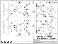
(You may want to open the schematic image in another window, or print it on paper, to follow the discussion in this section and quickly see which component is "C5", etc.)
C1, C3, R1, BR1, and C5 form an unremarkable, ordinary AC-to-DC rectifier and filter, plus Quasimodo snubbing. You'll notice I have used C3 = 1000 nanofarads, and 1000 != 150. I spoke to the Quasimodo inventor about this, explained my reasoning, and got his approval. So use 1000 nF in your build (see Detailed Parts List) and be happy.
Then ferrite bead FB1 converts high frequency noise on C5, into heat. The ripple waveform (now on C7) has far less high frequency noise.
NPN Darlington Q1 and its supporting components, forms a capacitance multiplier that is protected against overvoltage (ZD1) and turn on/off shocks (D1). Resistor R3 ensures that the collector-base voltage of Q1 never goes negative ... which could allow input ripple voltage to shoot straight through to the output.
Then L1 + C13 + (the DC resistance of L1) form a two pole LCR lowpass filter, attenuating high frequency noise quite effectively. The relatively pure, low noise DC signal on C13 is presented to Q3 and its supporting components.
The Q3 circuit can be considered a "clamped capacitance multiplier" because its output voltage is clamped and cannot exceed (approx!!) 19 volts, even as the input voltages rises far above 19V, thanks to U1 and ZD3. The relatively weird and unknown (but extremely CHEAP) adjustable shunt reference part called AZ431AZ is used, because it offers plus minus 0.4 percent accuracy for less than USD 0.50. Much better bang for the buck than the T.I. "TL431" which is pin compatible but less accurate.
Finally, there is an output rail fuse F1 and a ferrite bead FB3 to remove the last vestiges of high frequency noise. The fuse, a small thru-hole packaged device, blows if/when you mistakenly short UDP3's output. It is available on DigiKey and Mouser for about 40 cents per fuse. Because they cost so little, I recommend you buy at least six fuses of each of three different fusing currents. Or more. Now when you get a surprise fuse-blow event during testing, you will have plenty of spares, and they don't cost an arm and a leg.
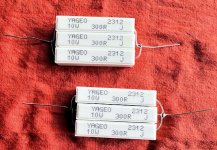
To test the first UDP3 prototype, I connected a pair of 100 ohm, 30 watt resistors to the UDP3 outputs (see photo below). These are cheap to buy and build, I suggest you get some too and test your UDP3 carefully before hooking it up to your precious Pearl 3. At plus and minus 19 volts output, these load resistors consume 190 milliamperes per supply, comfortably more than Pearl 3 draws. During testing with 190 mA load current, fuses rated 250 mA never blew.
HOWEVER, it's all but inevitable that some "hot rodder" types of builders, will add high current discrete opamps to Pearl 3. And increase the bias current in the BJT output stage. And possibly other stunts or gymnastic shenanigans which are unimaginable at the moment. Therefore UDP3 is deliberately over-designed, to provide 350 mA from +19V and 350 mA from -19V (with higher current fuses fitted of course!!) Heatsinking the pass transistors lets them operate comfortably even at these high current levels.
Schottky diodes D5 and D6 are panic protection components, whose only job is to set the rails to not-stupid voltages after a fuse blows.
WHO SHOULD COMPLETELY IGNORE UDP3?
A quick glance at the UDP3 schematic reveals that there are a LOT of components. Including four Euroblox connectors, four extruded aluminum heatsinks, eight super-low-ESR electrolytic capacitors, oh and by the way, a second chassis (!!). If you're hoping to build a cheap, cheap PSU for your Pearl 3 phonostage, this isn't it. Too many parts.
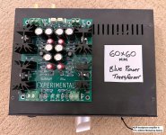
Similarly, if you're hoping to build a teeny tiny PSU that occupies very little chassis volume, UDP3 isn't for you. PCB size is 112mm X 132mm (mounting holes 100 x 120) and the heatsinks are an inch tall (25.4 mm). That doesn't even include the power transformer. See the photo of UDP3 atop a 170x230 Modushop "Galaxy" below.
Finally, if you're hoping for a "paint by numbers" audio project that doesn't require you to reason about electronics, not even once: UDP3 may not be a good project for you. There's no wiring diagram, there's no suggested part numbers for the AC mains IEC inlet or fuse holder or on/off switch, there's no transformer mounting recommendation, the list goes on and on. Avoid misery; don't attempt UDP3 if it is beyond your current builder-training-and-skill level.
ATTACHMENTS
The schematic, detailed Parts List, and PCB manufacturing Gerbers (.zip archive) are attached to this post, below. It is "Rev.A" -- the first official release of UDP3.
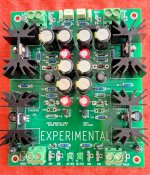
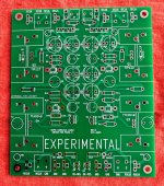
I've also got a few extra PCBs of the experimental prototype (rev.0) which are built on extra sturdy 2.0mm thick fiberglass, and are 50% stiffer than standard PCBs. {remember, stiffness is proportional to thickness squared}. Send me a selfie photo of yourself holding up your two chassis for Pearl 3 and UDP3, also holding the two bare Pearl 3 boards, and I'll send you a rev.0 UDP3 circuit board for $5.00. That's the cost of a mailer envelope and shipping via USPS.
- This lets you move the mains transformer far away from the sensitive Pearl 3 PCBs. Greater separation gives greater isolation.
- The external PSU chassis provides an electrostatic and electromagnetic shielding box, surrounding the mains transformer. This dramatically reduces noise radiated from the mains transformer and wiring.
- If desired, you can build an additional box-within-a-box, thereby double shielding the mains transformer. You don't have to worry whether the extra size and volume of the second box will intrude upon the Pearl 3 phonostage PCBs.
The UDP3 circuit is a cascade of several lowpass filters connected in series; it is NOT a voltage regulator and there are no negative feedback loops. This is intentional and deliberate; NFB loop gain generally falls as frequency rises, often at a slope of -20dB per decade of frequency. But we want lots of attenuation (a/k/a "PSRR") at high frequencies, exactly where NFB regulators poop out.
Instead, UDP3 uses ferrite beads and several cascaded filters (one of which is a two-pole LRC filter), to achieve excellent noise reduction even at radio frequencies. The big idea is: provide Pearl 3 with a pair of low-ripple, low-noise, RF-free raw DC voltages, and let Pearl 3's onboard voltage regulators do their job, when given pristine inputs.
The UDP3 outputs plus and minus nineteen volts (approximately! remember, UDP3 is not a regulator), which the 7815 and 7915 voltage regulator IC on the Pearl 3 boards, then reduce to smooth and regulated plus and minus 15 volts.
CIRCUIT DESCRIPTION
(You may want to open the schematic image in another window, or print it on paper, to follow the discussion in this section and quickly see which component is "C5", etc.)
C1, C3, R1, BR1, and C5 form an unremarkable, ordinary AC-to-DC rectifier and filter, plus Quasimodo snubbing. You'll notice I have used C3 = 1000 nanofarads, and 1000 != 150. I spoke to the Quasimodo inventor about this, explained my reasoning, and got his approval. So use 1000 nF in your build (see Detailed Parts List) and be happy.
Then ferrite bead FB1 converts high frequency noise on C5, into heat. The ripple waveform (now on C7) has far less high frequency noise.
NPN Darlington Q1 and its supporting components, forms a capacitance multiplier that is protected against overvoltage (ZD1) and turn on/off shocks (D1). Resistor R3 ensures that the collector-base voltage of Q1 never goes negative ... which could allow input ripple voltage to shoot straight through to the output.
Then L1 + C13 + (the DC resistance of L1) form a two pole LCR lowpass filter, attenuating high frequency noise quite effectively. The relatively pure, low noise DC signal on C13 is presented to Q3 and its supporting components.
The Q3 circuit can be considered a "clamped capacitance multiplier" because its output voltage is clamped and cannot exceed (approx!!) 19 volts, even as the input voltages rises far above 19V, thanks to U1 and ZD3. The relatively weird and unknown (but extremely CHEAP) adjustable shunt reference part called AZ431AZ is used, because it offers plus minus 0.4 percent accuracy for less than USD 0.50. Much better bang for the buck than the T.I. "TL431" which is pin compatible but less accurate.
Finally, there is an output rail fuse F1 and a ferrite bead FB3 to remove the last vestiges of high frequency noise. The fuse, a small thru-hole packaged device, blows if/when you mistakenly short UDP3's output. It is available on DigiKey and Mouser for about 40 cents per fuse. Because they cost so little, I recommend you buy at least six fuses of each of three different fusing currents. Or more. Now when you get a surprise fuse-blow event during testing, you will have plenty of spares, and they don't cost an arm and a leg.
To test the first UDP3 prototype, I connected a pair of 100 ohm, 30 watt resistors to the UDP3 outputs (see photo below). These are cheap to buy and build, I suggest you get some too and test your UDP3 carefully before hooking it up to your precious Pearl 3. At plus and minus 19 volts output, these load resistors consume 190 milliamperes per supply, comfortably more than Pearl 3 draws. During testing with 190 mA load current, fuses rated 250 mA never blew.
HOWEVER, it's all but inevitable that some "hot rodder" types of builders, will add high current discrete opamps to Pearl 3. And increase the bias current in the BJT output stage. And possibly other stunts or gymnastic shenanigans which are unimaginable at the moment. Therefore UDP3 is deliberately over-designed, to provide 350 mA from +19V and 350 mA from -19V (with higher current fuses fitted of course!!) Heatsinking the pass transistors lets them operate comfortably even at these high current levels.
Schottky diodes D5 and D6 are panic protection components, whose only job is to set the rails to not-stupid voltages after a fuse blows.
WHO SHOULD COMPLETELY IGNORE UDP3?
A quick glance at the UDP3 schematic reveals that there are a LOT of components. Including four Euroblox connectors, four extruded aluminum heatsinks, eight super-low-ESR electrolytic capacitors, oh and by the way, a second chassis (!!). If you're hoping to build a cheap, cheap PSU for your Pearl 3 phonostage, this isn't it. Too many parts.
Similarly, if you're hoping to build a teeny tiny PSU that occupies very little chassis volume, UDP3 isn't for you. PCB size is 112mm X 132mm (mounting holes 100 x 120) and the heatsinks are an inch tall (25.4 mm). That doesn't even include the power transformer. See the photo of UDP3 atop a 170x230 Modushop "Galaxy" below.
Finally, if you're hoping for a "paint by numbers" audio project that doesn't require you to reason about electronics, not even once: UDP3 may not be a good project for you. There's no wiring diagram, there's no suggested part numbers for the AC mains IEC inlet or fuse holder or on/off switch, there's no transformer mounting recommendation, the list goes on and on. Avoid misery; don't attempt UDP3 if it is beyond your current builder-training-and-skill level.
ATTACHMENTS
The schematic, detailed Parts List, and PCB manufacturing Gerbers (.zip archive) are attached to this post, below. It is "Rev.A" -- the first official release of UDP3.
I've also got a few extra PCBs of the experimental prototype (rev.0) which are built on extra sturdy 2.0mm thick fiberglass, and are 50% stiffer than standard PCBs. {remember, stiffness is proportional to thickness squared}. Send me a selfie photo of yourself holding up your two chassis for Pearl 3 and UDP3, also holding the two bare Pearl 3 boards, and I'll send you a rev.0 UDP3 circuit board for $5.00. That's the cost of a mailer envelope and shipping via USPS.
Attachments
-
 image_schematic_Rev_A.png41.2 KB · Views: 1,438
 -
 Galaxy_170_x_230_UDP3.jpg430.4 KB · Views: 1,031
 -
 soldered_pcb.jpg834.6 KB · Views: 837
 -
 bare_pcb.jpg751.4 KB · Views: 785
 -
 load_resistors.jpg129.6 KB · Views: 960
 -
UDP3_schematic_Rev_A.pdf39.7 KB · Views: 206
-
Gerbers_UDP3_umbilical_Rev_A.zip51 KB · Views: 173
-
PartsList_UDP3_revA.zip8.3 KB · Views: 234
Last edited:
If anybody is thinking about designing their own umbilical cable driver board, hoping for even better performance (higher PSRR, lower noise, etc) than UDP3 . . . .
Here are a couple things you might consider. They were "too scary" for me and I didn't use them in the UDP3 design, partly because they are single-source and thus likely to go on 52-week backorder at any time without notice, and partly because I believed that nobody wants SMD parts in their PSU. SMD JFETs in their RIAA preamp stage? Maybe, if there's no other choice. But in the PSU? No way Jose.
In the hands of a talented and brave designer, these appear to offer an opportunity for superior performance. Me, I'm not quite that brave.
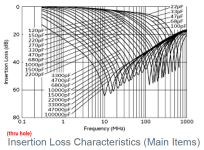
1. Murata thru-hole filter containing 2 ferrite beads and a 3-terminal feedthrough capacitor (Mouser P/N 81-DSS1NB31H104Q91A)
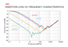
2. TDK 3-terminal feedthrough capacitor in SMD package (Mouser P/N 810-YFF31HC2A105M).
Unfortunately Mouser's datasheet links are coprolite so I've attached the correct .pdfs which I downloaded from the manufacturers' websites.
Here are a couple things you might consider. They were "too scary" for me and I didn't use them in the UDP3 design, partly because they are single-source and thus likely to go on 52-week backorder at any time without notice, and partly because I believed that nobody wants SMD parts in their PSU. SMD JFETs in their RIAA preamp stage? Maybe, if there's no other choice. But in the PSU? No way Jose.
In the hands of a talented and brave designer, these appear to offer an opportunity for superior performance. Me, I'm not quite that brave.
1. Murata thru-hole filter containing 2 ferrite beads and a 3-terminal feedthrough capacitor (Mouser P/N 81-DSS1NB31H104Q91A)
2. TDK 3-terminal feedthrough capacitor in SMD package (Mouser P/N 810-YFF31HC2A105M).
Unfortunately Mouser's datasheet links are coprolite so I've attached the correct .pdfs which I downloaded from the manufacturers' websites.
Attachments
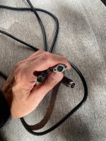
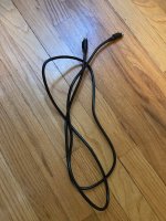
Thinking of using this power cord and sockets as an umbilical for the UDP.
Pros:
6' long, off the shelf 4-pin shielded cable, 18 AWG. Rated max 48V DC, 7.5A.
I've got a couple cables & their sockets left over from an abandoned project.
Cons:
Maybe overkill?
No idea if the inherent resistance and capacitance of this cable & it's sockets would cause a deleterious loading effect to the power supply.
One might recognize this Kycon KPP-4P connector as the same used in the Meanwell bricks spec'd for the Sony V-FET lottery amp. Plugging that brick into one's UDP3, or a Pearl 3 for that matter, would be an obvious disaster.
Attachments
Making a project at Mouser and reviewing the parts list... Line #22 Mouser PN should read: "757-TTA004BQ". "A" vs "C" for the PNP part. Mark did say this wasn't paint by numbers. !!
Thank you Mark for a PN for fastons with nice supportive tabs that don't cost $0.25 each!
Thank you Mark for a PN for fastons with nice supportive tabs that don't cost $0.25 each!
Great project Mark! I think this will come in handy for all sorts of projects. Much appreciated.
I haven't studied the schematic yet (only a quick read-through) but was wondering if it would be easy to change the output to a higher or lower voltage. The Pearl 2 springs to mind (+/- 24V regulated, so it probably needs to be fed with +/- 28V) as well as some preamps with varying voltage requirements.
Rather than asking for the partnumbers for different voltages, it might be a good project to learn more about LTspice and how parts affect the circuit. Is there a spice file for this schematic? Ideally with the required models? The main drawback I have found whenever I try something in LTspice is that I can spend hours or days hunting for a model.

Fascinating Exercise..
Recently inherited a pile of New (still in cellophane) Lps. typically most of the late 60's 70's faves.
Effectively Duplicates of mine.
So did a lil A -B comparison .. given it was accepted knowledge 'back then' that Lps lost quality after a v few playbacks.
V surprising result.. Far more than i had assumed actually.
NEW Lps sound dramatically different from my oldies.. Crisp, more dynamic , more presence.
My lps are /were lightly used. Having been played on My bought in 1969 Thorens ..with a variety of quality carts over the years.
I say this only to claim that my Lp s received Good use / care (No coins on a garrard cart abuse)
Now know why some claim that Vinyl outsounds CDs.. cuz it's demonstrably True ....IF the lp is New")
Genuine respect for Vinyl LPs' .
Does make me suspect the value of serious digging for diminishing returns in playback device sophistications..
When the Vinyl medium is Sooo subject to painfully obvious use degradations.
Yesss.. the journey is the adventure, Not the destination.
Recently inherited a pile of New (still in cellophane) Lps. typically most of the late 60's 70's faves.
Effectively Duplicates of mine.
So did a lil A -B comparison .. given it was accepted knowledge 'back then' that Lps lost quality after a v few playbacks.
V surprising result.. Far more than i had assumed actually.
NEW Lps sound dramatically different from my oldies.. Crisp, more dynamic , more presence.
My lps are /were lightly used. Having been played on My bought in 1969 Thorens ..with a variety of quality carts over the years.
I say this only to claim that my Lp s received Good use / care (No coins on a garrard cart abuse)
Now know why some claim that Vinyl outsounds CDs.. cuz it's demonstrably True ....IF the lp is New
Genuine respect for Vinyl LPs' .
Does make me suspect the value of serious digging for diminishing returns in playback device sophistications..
When the Vinyl medium is Sooo subject to painfully obvious use degradations.
Yesss.. the journey is the adventure, Not the destination.
So did a lil A -B comparison .. given it was accepted knowledge 'back then' that Lps lost quality after a v few playbacks.
V surprising result.. Far more than i had assumed actually.
NEW Lps sound dramatically different from my oldies.. Crisp, more dynamic , more presence.
How do you know that the matching LPs sounded the same when both were new?
It's unlikely, especially if they were made in different production runs, or even in different years.
I have some new old stock records that are pretty awful. I think some of the vinyl was recycled with old tires and road debris added.
A sealed NOS "miracle surface" RCA Living Stereo LP had noise that sounded like a terrible rainstorm.
"Treated with antistatic ingredient 317X."
You'd have to do some pretty significant re-engineering. The minimax optimizations required to deal with max-ACmains-voltage, min-ACmains-voltage and also secondary-voltage-droop-full-load vs secondary-voltage-no-load, and then component tolerances etc., will probably be cumbersome. That's if you want your Umbilical Driver Not For Pearl 3, to have no trimmer potentiometers whatsoever (as was done in UDP3). If you install appropriate test-points on the board, design in a few trimmer pots, and accept the reality that you must test the final unit with a Variac {to minimax the AC mains input} plus a pair of 100 ohm, 30 watt load resistors as shown in post 1, you can choose a safe operating point (far away from The Cliffs Of Death) on the lab bench. Either way it will be a lot of work and you should expect to place about three parts-orders at DigiKey before it's finished. The first order is the parts you think you need. The second order happens after you've tested the prototype and discovered that changes are required. The third order happens after you've tested rev.B and found that it's still not quite right.... would it be easy to change the output to a higher or lower voltage. The Pearl 2 springs to mind (+/- 24V regulated, so it probably needs to be fed with +/- 28V) as well as some preamps with varying voltage requirements.
- Home
- Amplifiers
- Pass Labs
- UDP3: Umbilical Cable Driver for Pearl 3 phonostage -- move Pearl 3 PSU into its own, distant, chassis