Thanks Mark. Haha, not being hindered by knowledge, I had hoped it would be a (relatively simple) matter of changing the voltage reference points and possibly using higher voltage specced parts (e.g. capacitors) if required, but I understand that was a too simplistic.
Impressive work! I was wondering: if one was to regulate the voltages for a Pearl 3 with a Jung-Didden super regulator (instead of 7x15), would there still be a benefit in using the UDP3 compared to for instance a simpler PSU consisting of IEC inlet filter (Schaffner 9222 or somthing like that), snubber, CRCRC (or ...LC) filter and maybe even 7x24 pre-regulators? Of course the UDP3 will provide a cleaner voltage to the super regulator, but would there still be a measurable (audible?) effect after the super regulator?

I was afraid you were going to say that 🙂
For now I will stay with my Pearl 2. First project will be to build a Quasimodo to calculate snubbers for its PSU (which uses soft recovery diodes which, according to the manufacturer "eliminate snubbers")
For now I will stay with my Pearl 2. First project will be to build a Quasimodo to calculate snubbers for its PSU (which uses soft recovery diodes which, according to the manufacturer "eliminate snubbers")
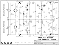
Readers of this thread might get a couple of chuckles or minor amusement from posts #1 - #3 on (another thread). Those members say that output protection diodes (exactly like D5 and D6 on the UDP3 schematic) improve "low high mid very details". Who knows, in their experiments, on their gear, in their listening room, using their source material -- perhaps it does. Please enjoy their thread as a bit of jolly mirth, and acrimony-less diversion.
_
_
Attachments
This power supply is very well thought out. Mark has a reason for all the parts, some of which I learned about the hard way.
The no feedback filter/regulator is what is used in Pass pre products before the actual pre-amps regulation in multi chassis products.
We use three terminal and discrete regulators after that depending on the product.
The no feedback filter/regulator is what is used in Pass pre products before the actual pre-amps regulation in multi chassis products.
We use three terminal and discrete regulators after that depending on the product.
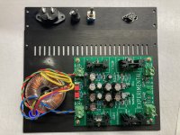
Some progress today. UDP3 board finished with Rs snubber value, baseplate drilled & trafo and board mounted. Will finish drilling and filing out the backplate and mounting the plugs & sockets before power up, most likely.
Attachments
It looks like you purchased and installed and soldered C3 = C4 = 1000 nF = 1.0 microfarad as shown in the schematic and parts list; those red WIMA box caps look familiar. Post #1 of this thread says,
If you run it on Quasimodo, remember to use 1000 nF and not 150 nF in your QM testing.
You'll notice I have used C3 = 1000 nanofarads, and 1000 != 150. I spoke to the Quasimodo inventor about this, explained my reasoning, and got his approval. So use 1000 nF in your build (see Detailed Parts List) and be happy.
If you run it on Quasimodo, remember to use 1000 nF and not 150 nF in your QM testing.
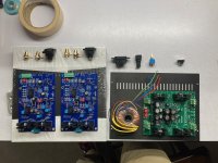
I did indeed Mark, thanks for checking! One can just see the same red box Wima 1uF and little pale yellow guy in the photo below of my Quasimodo testing rig. I would be curious to know the rationale behind the change in the snubber capacitance values for the UDP3.
Attachments

For my transformer there was a negligible difference in Quasi waveform for the 1uF vs 0.15uF "standard"....22R in my case seemed to look the best, per the docs.
I spoke to the Quasimodo inventor about this, explained my reasoning, and got his approval.
This is still my favorite line in the whole thread.

So, now we've gone through all that trouble filtering out HF energy with the UDP3, won't the umbilical itself just pick that up again? Wifi, radio, cellphones etc... Is a screened umbilical more or less mandatory when you want to preserve that clean voltage?
I used a shielded umbilical for my Salas UltraFSP build. Of course, shield only connected on the raw power supply end.
As a matter of course I always twist power umbilical lines and run through braid. If you do this you will also want connectors with what are essentially EMI backshells to keep anything out at the terminations.
Is a screened umbilical more or less mandatory when you want to preserve that clean voltage?
Yes, exactly correct.
Following the nosebleed audio mantra, "Anything worth doing is worth over-doing", it is certainly possible to have more than one screen in an umbilical cable.
Setting aside the questions of whether this is a good idea, or a good expenditure of resources (answers: no and no); certainly it is possible to assemble a DIY umbilical cable that includes
and I'll bet members can devise even more elaborate cabling schemes and contrivances.
Setting aside the questions of whether this is a good idea, or a good expenditure of resources (answers: no and no); certainly it is possible to assemble a DIY umbilical cable that includes
- A twisted pair of (POS19 and GND), with a screen around that twisted pair
- A twisted pair of (NEG19 and GND), with a screen around that twisted pair
- An insulating sleeve surrounding both of the screened pairs above
- A screen around the insulating sleeve
- A high current green-and-yellow Protective Earth wire surrounded by a screen
- A second insulating sleeve around the entire cable assembly
and I'll bet members can devise even more elaborate cabling schemes and contrivances.
Last edited:
Thanks Mark!
Perfect on first try.
(chassis still in process)

Perfect on first try.
(chassis still in process)
Some people are worried that the same heatsink (AAVID 529702) is used for the TO-220 packaged Darlingtons and for the Toshiba TO-126 packaged singleton BJTs with high-fT and high-Beta. But, but, but ... the worry warts blubber ... the distributor says that heatsink is only for TO-220 and not for TO-126. Attachment below.
Fortunately, fearless amplifier builders actually TRIED the combination, and in practice: son of a gun, it actually works just fine. This is because (a) even though the transistor mounting bolt-hole on the heatsink is far, far away from the PCB surface, a TO-126 has leads long enough to penetrate all the way through the board and offer plenty of leg length on the other side for your soldering iron; (b) diyAudio members generally order standard-thickness PCBs (1.6 mm thick) and not I-am-a-crazy-person extra thick PCBs (3.0 mm + huge price increase).
I recommend you use the heatsinks in the UDP3 price list. They work. Look at the photos in post #39 above. The TO-126 transistors + heatsinks work together delightfully on the PCB. Despite what DigiKey and AAVID might caution you.
_
Attachments

- Home
- Amplifiers
- Pass Labs
- UDP3: Umbilical Cable Driver for Pearl 3 phonostage -- move Pearl 3 PSU into its own, distant, chassis