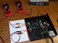
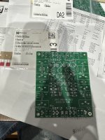
I powered up first time for testing if everything looked ok. It seems so.
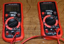
I get -+ 18.9 VDC out with 100R as load resistors. AC-in is 2 x 22.3 VAC.
I will let it "cook" for some time.
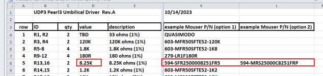
Reason for 18.9 VDC and not a bit higher might be that the 8k25 resistor which has something to do with the adjustable voltage reference I installed 8k2 as I already had those. I measured them to find high values but they were just low on 8k2. But think I am ok with 18.9 V. There will be a little bit of loss in cable but still at least 3.5 V for the 15V regulators to regulate. I guess it is about perfect.
I get -+ 18.9 VDC out with 100R as load resistors. AC-in is 2 x 22.3 VAC.
I will let it "cook" for some time.
Reason for 18.9 VDC and not a bit higher might be that the 8k25 resistor which has something to do with the adjustable voltage reference I installed 8k2 as I already had those. I measured them to find high values but they were just low on 8k2. But think I am ok with 18.9 V. There will be a little bit of loss in cable but still at least 3.5 V for the 15V regulators to regulate. I guess it is about perfect.
Attachments
Yes, 18.9 volts is indeed "approximately 19 volts" as the UDP3 design promises, and Pearl 3 will operate perfectly normally with that input voltage. A margin-of-safety has been included, to accommodate any additional voltage dropped across the umbilical cable and the DC connectors.
It is not a wise move to haphazardly change resistor values in the control circuitry of a chip (AZ431AZ) that you paid extra money for, to get a guaranteed accuracy better than 0.4%. Especially when the Detailed Parts List presents another option.
_
It is not a wise move to haphazardly change resistor values in the control circuitry of a chip (AZ431AZ) that you paid extra money for, to get a guaranteed accuracy better than 0.4%. Especially when the Detailed Parts List presents another option.
_
Attachments
Last edited:

Yes, yes I know......but my assumption then was that I had the 8k2 and I calculated the value to be within the +-1% 🙂
I also measured the 8k2 I used to be sure there were within the limit of -1%.
I looked a little bit into the voltage reference to try to predict if I would get a bit lower or higher voltage. I think I concluded that maybe the voltage would be a little bit lower.
It has run for a couple of hours now and only the load resistors gets really not. Mechanical it is 100% silent.
I tried the inrush test a number of times to see is primary fuse (160 mA T) could take it. Toroidy specifies 160 or 180 mA T for the 20 VA transformer.
Looking at DMM it takes 8-9 sec. to reach the final 18.9 VDC.
Completed my UDP3 and Pearl and it's sounding great. An observation on the UDP3, I generally do some laser temperature checks to see if anything is running hot, and I was surprised to see C14 and C13 warming up just above 30C. It's unusual for me to see electrolytics warming up, although I know it can happen from ripple current. The voltage references are also running around 38C and R15 in particular is running around 40C after being on for more than an hour. Output voltages are good (18.9). Is this all normal? Thanks for the projects, they were quite easy to build and fired up first time.
to see C14 and C13 warming up just above 30C
This is a guess, and I haven't measured temperatures on mine, but are you using the super low ESR Panasonic FM caps that Mark spec'd? Logic suggests that higher ESR will have a greater voltage drop across the cap, hence more heat.
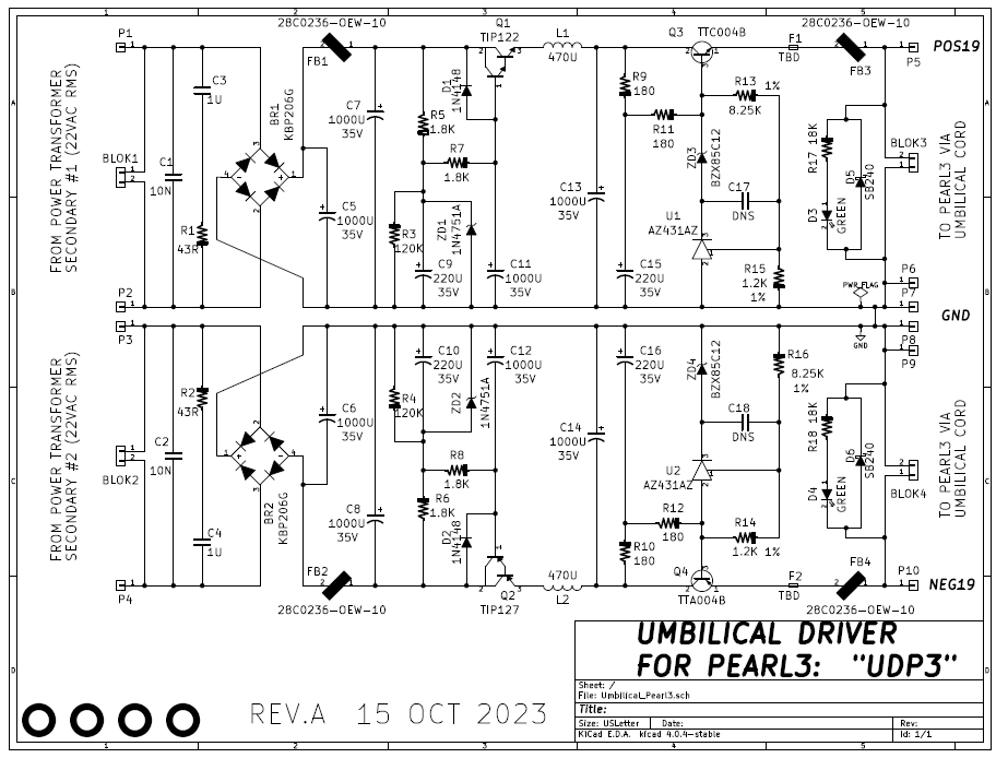
If the circuit has been assembled correctly, and if none of the components are faulty, then chip U1 regulates the voltage across R15 to be 2.50 volts. Thus the power dissipated in R15 is (2.5 * 2.5 / 1200) = 0.0052 watts. Five milliwatts. Which doesn't produce much heat at all. And if everything is working correctly, the power dissipated by R15's brother R13 should be 6.9x higher. So if R15 is hot, R13 should be way waaay hotter. But you don't mention that R13 is warm.
Similarly, in a correctly assembled board with all good components, the ripple current in C13 and C14 is negligibly small. That's because the AC component of the voltage across C13 and C14 is negligibly small. And, in turn, that's because the AC component of the voltage has previously been severely attenuated by "ripple killer" Q1/Q2 and further attenuated by L1/L2. Applying a tiny AC voltage component to C13/C14 gives a tiny AC current component (a/k/a ripple current). Therefore C13 and C14 don't warm up at all. In a correctly built board with 100% good parts.
Thus it is surprising to hear that R15 and C13 and C14 are warm; they shouldn't be. I suggest you try a different thermometer, ideally an infrared camera, to check whether your temperature measurements are repeatable. I myself bought (this infrared camera) for diyAudio projects and love the results I get.
I also suggest you measure the voltage across the two terminals of R15. If it's not 2.50 volts then there is definitely something wrong with your board. If it IS 2.50 volts and if R15 is warm, then R15's resistance is definitely wrong, and R15's resistance is way waaay less than 1200 ohms.
The components that might get warm, are R9, R11, and ZD3. This could happen when using a transformer whose secondaries are 22VAC or higher, and also running your UDP3 board at a small load current or zero load current -- such as when testing the UDP3 board with no load resistor and/or no Pearl 3 connected to the POS19 & NEG19 outputs. Warm, not burning hot.
Last edited:
Thanks for the replies, I built the board with the low ESR capacitors specified in the BOM. Mark, you could be right about my thermometer not being perfectly accurate, however the "touch test" I did after removing power showed the caps were indeed just slightly warm, not remotely hot, just warm. It's also possible that R15 is not actually that hot, and it's a surrounding component, like U1. I measured across R15, and I get 2.48V. I also verified by measuring 1.2k for R15, then I went back and verified every other resistor on the board, and measured the raw resistors I used to make sure something wasn't mislabeled. They are all correct. However, I do suspect something is wrong on the positive side of the board. The negative side is warming up measurably less (maybe 2 degrees C above ambient rather than 5-8C on the positive side), and I now measure -18.9 on the negative side, and 18.77 on the positive side as output voltages. The only component substitution I made was using a TIP121 instead of a TIP122 because of lack of availability. Could something be wrong with either the TIP121 or the TTC04B? I have another TIP, but not another TTC, however I can always find something to order from Mouser or Digikey, so I could easily get another one. Other things to check?
Thanks so much for the offer ranshdow! I've found them at Mouser and I need to order some other stuff from them this week, so I'm good. Much appreciated though!
Replaced the TIP121 with a 122, and things have improved. The 121 must've been bad, as I see no reason why that sub shouldn't work identically. Anyways, R15 no longer gets warm, and overall the caps warm up just slightly, but nowhere close to an issue, the output is stable and the pre sounds great! Thanks guys.
Just a tip - these can be quite handy, if you for some reason need to change a fuse.
https://www.mouser.dk/ProductDetail/693-0031.7601
https://www.mouser.dk/ProductDetail/693-0031.7601
Just a minor detail but I really like the terminal blocks that are used for UDP3 rather than the type that is in P3 kit (which is the standard type most use in general and it of course works fine also). The UDP3 type has a true parallel action when it applies presseure where the other is a screw that press on a small tap that is connected in one end.
Please have a look at the following discussion thread here on the Forums:
A zip archive of Gerber files for the UCP3 PCB are attached to post #1 of this thread; anybody can download the .zip for free, and send it off to whichever PCB fab they like.
You might search the "Swap Meet" and/or "Group Buys" area of the Forums to see whether anyone is offering UDP3 boards or not.
Hi Mark,Please have a look at the following discussion thread here on the Forums:
A zip archive of Gerber files for the UCP3 PCB are attached to post #1 of this thread; anybody can download the .zip for free, and send it off to whichever PCB fab they like.
You might search the "Swap Meet" and/or "Group Buys" area of the Forums to see whether anyone is offering UDP3 boards or not.
Thanks so much for the quick reply. This is a great thread with lots of info, much appreciated. I'm very excited for this build!
@pfarrell PM answered👍 You guys are awesome.
- Home
- Amplifiers
- Pass Labs
- UDP3: Umbilical Cable Driver for Pearl 3 phonostage -- move Pearl 3 PSU into its own, distant, chassis