I built a bridged F5m which I am calling the F5mX. It is pretty minimal for a bridged amp.
It is pretty much a F5m that is bridged plus a few little tricks. The most interesting thing is that it has CCS resistors on the OS stage. They are oriented on opposite rails on the opposing phases to hopefully break a little bit of symmetry and give us a little 2nd harmonic distortion.
The Schematics and the BOM are in the 2nd and 3rd post.
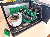
The power supply has the bridge rectifiers integrated in the board. You can see I snip the terminals after soldering. Keep in mind that snipping the terminals off is easier without the caps mounted. Snipping them off also makes it a bit easier to desolder the bridges if ever needed. The PSU has 70uF film caps bypassing the last stage of the CRC cap bank. The EL caps are 24x10,000uF 35v. Ground lift is on the board and connects through the standoff. there is also a Quasimodo Snubber circuit on the board which I recommend using. My transformer required a 7 ohm resistor for RS1 and RS2. A 8-10 ohm resistor would work as well.


The front end connects to the output stages with two 16 pin (2 rows of 8) female to female ribbon cables. I bought the ribbon cables and sockets from Amazon. I did have to shorten them as they are very long. It is not very difficult to do.
Each channel on the front end pulls it's power supply from the output stage via the ribbon cables. There is a single ground wire connecting to the PSU which you can see in the pic below. The front end mounts to the standoffs that the power supply mounts to the bottom panel with. So you have short standoffs under the PS, then tall standoffs going from the PS to the front end. I made the standoff holes on all the boards large enough to accomodate #6 thread so you can use either your typical metric standoffs or larger #6. The OS simply mounts by being soldered to the leads on the IRFP140/9240 mosfets. When you assemble the front end, it is good to reduce the resistance of the pots to their minimum setting. This will make it so that they are not biasing the output stage upon first startup. I used Dale resistors as there are so few, and they are convinient for troubleshooting so long as you are careful to face the value labels upwards.
There are spots for source resistors on the JFETs (the 10 ohms) but you can jump as you see in the photo below (between the JFETs). These are there to allow a bit of flexibility in the event that someone wants to experiment.


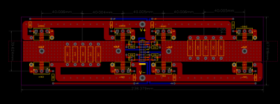
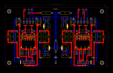
The front end takes one quad of J74/K170 Toshiba JFETs per channel. The outputs are two pairs of IRFP140/9140 (one pair per phase). However, there are spots for 4 pairs of output devices per channel so you can experiment. I used 0R36 source resistors and it behaved great. However feel free to use the standard 0R47. If you are only using the four mosfets per channel, feel free to skip the gate resistors just like on the regular F5m. There are spots for thermistors on the OS board to make the bias more agressive at a cold startup but I haven't tested this yet. It works just fine without them. As you can see, I have four of the 2.2k CCS resistors populated per phase. I like this amount but you can try more or less. I use ceramic insulators on the mosfets but feel free to use the stores insulators. They are great!

I have had it biased at about 50-60 watts of class and have tested it up to about 110 watts in class B. Assuming you are using a quad of outputs per channel, and have a 5u chassis, with your 0R47 source resistors, use the normal say .500v per mosfet and see how hot things get. If you use 0R36 resistors, you can set it to 0.380v accross a source resistor. Then lower or raise it accordingly. If you are using 4 pairs of mosfets per channel, drop the bias per device in half and tune for temperature.
The transformer that I am using is a 22vac 800va which is giving me around 26.5vdc rails. Antek gave me simple instructions on others ordering this same transformer.

The boards are set up for UMS spacing. The power supply board and the soft start board has the holes set to 10mm spacing so they should bolt right up to the preferated bottom plate that DIYaudio sells. One board set includes:
Front end board
two output supply boards
one power supply board
one soft start board

Okay, the sound. Well, the F5m is excellent! The F5mX is cleaner, more detailed, and can make more power... I have been enjoying it quite a bit. Due to the CCS, it is not steril. However, if you have a good tube source you really like, then that is just wonderful. I have a tube DAC which really plays well with this amp. The highs are very very detailed. In the highs, the F5mX is all telling. But overall still a bit relaxed like the F5m. The bass is fairly tight but doesn't make a point of itself. For me, what I appreciate is the interaction between the mids and highs. It has no problem commanding a large space with my 89dB sensitive floorstanders.
The boards are $45 a set. If you have a DIYaudio paid membership, you get a $5 discount! 🙂 I will have my first 10 sets in about a week.
It is pretty much a F5m that is bridged plus a few little tricks. The most interesting thing is that it has CCS resistors on the OS stage. They are oriented on opposite rails on the opposing phases to hopefully break a little bit of symmetry and give us a little 2nd harmonic distortion.
The Schematics and the BOM are in the 2nd and 3rd post.
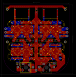
The power supply has the bridge rectifiers integrated in the board. You can see I snip the terminals after soldering. Keep in mind that snipping the terminals off is easier without the caps mounted. Snipping them off also makes it a bit easier to desolder the bridges if ever needed. The PSU has 70uF film caps bypassing the last stage of the CRC cap bank. The EL caps are 24x10,000uF 35v. Ground lift is on the board and connects through the standoff. there is also a Quasimodo Snubber circuit on the board which I recommend using. My transformer required a 7 ohm resistor for RS1 and RS2. A 8-10 ohm resistor would work as well.
The front end connects to the output stages with two 16 pin (2 rows of 8) female to female ribbon cables. I bought the ribbon cables and sockets from Amazon. I did have to shorten them as they are very long. It is not very difficult to do.
Each channel on the front end pulls it's power supply from the output stage via the ribbon cables. There is a single ground wire connecting to the PSU which you can see in the pic below. The front end mounts to the standoffs that the power supply mounts to the bottom panel with. So you have short standoffs under the PS, then tall standoffs going from the PS to the front end. I made the standoff holes on all the boards large enough to accomodate #6 thread so you can use either your typical metric standoffs or larger #6. The OS simply mounts by being soldered to the leads on the IRFP140/9240 mosfets. When you assemble the front end, it is good to reduce the resistance of the pots to their minimum setting. This will make it so that they are not biasing the output stage upon first startup. I used Dale resistors as there are so few, and they are convinient for troubleshooting so long as you are careful to face the value labels upwards.
There are spots for source resistors on the JFETs (the 10 ohms) but you can jump as you see in the photo below (between the JFETs). These are there to allow a bit of flexibility in the event that someone wants to experiment.
The front end takes one quad of J74/K170 Toshiba JFETs per channel. The outputs are two pairs of IRFP140/9140 (one pair per phase). However, there are spots for 4 pairs of output devices per channel so you can experiment. I used 0R36 source resistors and it behaved great. However feel free to use the standard 0R47. If you are only using the four mosfets per channel, feel free to skip the gate resistors just like on the regular F5m. There are spots for thermistors on the OS board to make the bias more agressive at a cold startup but I haven't tested this yet. It works just fine without them. As you can see, I have four of the 2.2k CCS resistors populated per phase. I like this amount but you can try more or less. I use ceramic insulators on the mosfets but feel free to use the stores insulators. They are great!
I have had it biased at about 50-60 watts of class and have tested it up to about 110 watts in class B. Assuming you are using a quad of outputs per channel, and have a 5u chassis, with your 0R47 source resistors, use the normal say .500v per mosfet and see how hot things get. If you use 0R36 resistors, you can set it to 0.380v accross a source resistor. Then lower or raise it accordingly. If you are using 4 pairs of mosfets per channel, drop the bias per device in half and tune for temperature.
The transformer that I am using is a 22vac 800va which is giving me around 26.5vdc rails. Antek gave me simple instructions on others ordering this same transformer.
The boards are set up for UMS spacing. The power supply board and the soft start board has the holes set to 10mm spacing so they should bolt right up to the preferated bottom plate that DIYaudio sells. One board set includes:
Front end board
two output supply boards
one power supply board
one soft start board
Okay, the sound. Well, the F5m is excellent! The F5mX is cleaner, more detailed, and can make more power... I have been enjoying it quite a bit. Due to the CCS, it is not steril. However, if you have a good tube source you really like, then that is just wonderful. I have a tube DAC which really plays well with this amp. The highs are very very detailed. In the highs, the F5mX is all telling. But overall still a bit relaxed like the F5m. The bass is fairly tight but doesn't make a point of itself. For me, what I appreciate is the interaction between the mids and highs. It has no problem commanding a large space with my 89dB sensitive floorstanders.
The boards are $45 a set. If you have a DIYaudio paid membership, you get a $5 discount! 🙂 I will have my first 10 sets in about a week.
Last edited:

Here are the schematics for the front end, the OS and the power supply as well as two pictures of everything assembled.
Attachments
-
 20241231_145425.jpg597 KB · Views: 524
 -
 20241231_141722.jpg570.4 KB · Views: 539
 -
 1735964147299.png432.5 KB · Views: 488
 -
 1735964087337.png209.5 KB · Views: 428
 -
 1735964061713.png262.2 KB · Views: 500
 -
Schematic_X-F5m-FRT_2025-01-03.pdf127.9 KB · Views: 406
-
Schematic_F5mX-output-4-pairs-DIYaudio_2025-01-03.pdf92.3 KB · Views: 359
-
Schematic_Cap-bank-24x10000uf-Kemet_2025-01-03.pdf71.9 KB · Views: 291
I liked the F5m so much that I was interested in doing a turbo type of F5. But then I thought it would be interesting to try a bridged F5m'ish amp that takes advantage of some of the tricks that Pass used to make the F5m happen.Lets get things flowing. What prompted you to create this amp ?
The balanced aspect is pretty cool in that the output supply is really fast.
-You don't have to increase the rail voltage to 32v in order to get the 50 watts of class A
-No cascodes, lots of current
-A healthy 110w class B envelope
-The feedback structure makes it so that you don't have to fuss about making the power supply as quiet as you would with a non-balanced design... So a fast power supply is really nice.
-All at the cost of an extra quad of JFETs and their associated parts.
The end result is what I expected. A nice detailed amp that is still relatively simple. When I play songs with lots of bass, things will be rattling in the house and the vocals will still be floating in the middle of the soundstage seemingly unaffected.
Mike brought this over to my house a couple weeks ago, it’s absolutely fantastic.
🙂 🙂 🙂
🙂 🙂 🙂
- 800VA transformer
- 2 filter capacitor banks of 120,000 microfarads each
- no inrush current limiting or soft start anywhere?
Mark, I am glad you brought it up. The board is designed around 120V. So for 240 V supplies, people may need to get creative.... I will probably add the silk-screening on the bottom to accommodate 240V the future.
I have 6 of 9 sets reserved so far. The PCBs are due to arrive within the next few days weather permitting (there is a big winter storm at the moment)
Thank you to all that reserved PCBs! I am excited for some other people to build this amp. 🙂
Thank you to all that reserved PCBs! I am excited for some other people to build this amp. 🙂
Curious and have a few questions.
1) Estimate on component costs? I didn't throw everything into a Mouser project yet.
2) Which chassis do you recommend from the store?
3) It's been a while since I built anything Pass related. FETs available where?
4) Any issues using it single ended? I see you wired yours with XLR and RCAs.
Thanks for sharing. Looks like a great project.
1) The mouser BOM added up to around $200 or so for me shipped with taxes. The transformer from Antek $111.20 shipped to me in CO. Then the JFETs for an octet from the DIY store are $90 plus shipping. There is wiring, binding posts, RCA's XLR's and other various parts so you can sort those out. I believe the Store has some of these available.
2) My recommendation would be the 5U chassis. The output supply boards are designed to accommodate the UMS layout of a 4U 300mm chassis. And honestly, that would be kind of cool. Kind of like a Mini V8... However, I think the 5U chassis really takes advantage of the class A capability. Also, if going 4U, you would have to vertically mount a transformer (probably a 400VA 20VAC) and even then it would be tight. So shoot for the 400mm deep 5U or larger. 4U would be good for say 25-30 watts. 5U would be good for 50 watts or maybe a bit more.
3) The JFETs are available at the store. IRFP140/9140's are available on mouser and Digikey and are in the BOM. there are not FETs on this amp which is nice.
4) I have used it with RCA and XLR just fine. You need to tie the negative and GND for the RCA connection. I have the "U" shaped jumper that I bought from Pass Labs because I wanted to feel special. My favorite DAC that I like to run straight into the amp is a tube DAC with only SE connection.
So take the positive of your XLR and wire it to the positive of your RCA. Same with the ground. When you want to use RCA, jump - to GND and you are good.
Thank you for the reply with the details. Years ago, I thought about building an F5 Turbo. I have Magneplanars and the Turbo was probably the best choice. Your project seems like a suitable candidate. I do realize the types of amplifiers that are best for this speaker, but I have always wanted to build a larger Pass type amplifier. I have smaller Pass projects that were built for fun. If I move forward, I'll provide info.
Okay, the last set of boards have been reserved. 🙂
I will be ordering more within the next week.
I will be ordering more within the next week.
- Home
- Group Buys
- F5mX - A 50w bridged F5m... Sort of...