AmyAlice is a simple DC filter which you install between a noisy Switch Mode Power Supply, and a piece of audio gear that expects relatively smooth, clean, high purity DC power input. It's intended to be used with line level audio equipment, such as DACs, active crossovers, NuTube boxes, preamps, headphone amps, H2 generators, DIYA front end boxes, and so on. The maximum voltage AmyAlice can support is 48V and the maximum current it can deliver is 3A, which is plenty for line level gear, and sometimes enough for a sub- 5 watt power amp (like for example the ACA mini).
There already exists a very nice DC filter for SMPS, as a project in the diyAudio store, which I encourage you to investigate. AmyAlice is similar to the Store filter, the differences being
THEN WHY BUILD AmyAlice AT ALL?
The DC filter kit in the store has always been implemented with thru-hole components only. A large number of builders are certain they cannot possibly succeed with surface mount parts, and quite a few more simply refuse to even try. For them, and everyone else, the all-thru-hole, zero-SMD store kit is available.
However, as Forum readers are well aware, there are lots of new electronic components which are offered ONLY in SMD packages. High volume electronics manufacturing is all-SMD in Y2023, therefore component suppliers meet their customers' needs with all-SMD parts. This is particularly true of new components, which, by the very definition of the word "new", do not exist in legacy thru-hole designs. The whole world has moved on to SMD assembly.
A couple of new, SMD-only components are now available, which enable much better performance (i.e. greater noise attenuation) in SMPS DC filters. These SMD parts cannot be used on the Store PCB, or any other must-be-thru-hole-only board. But they CAN be used on AmyAlice because AmyAlice allows SMD components.
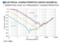
One such SMD component is the 1.0 microfarad, 3-terminal Feedthru Capacitor sold by TDK. Its datasheet, and the attenuation plot from that datasheet, are attached below. AmyAlice uses the "2A105" model of Feedthru Capacitor; as you can see, it offers spectacular HF attenuation, even at 100 kHz. AmyAlice actually includes two of these, so its attenuation is spectacular-squared.
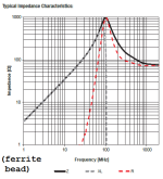
A second addition to AmyAlice is an SMD packaged ferrite bead from Wurth. The impedance curve of this bead is attached below; it rejects HF, RF, and VHF noise quite aggressively. The ferrite bead is the first series element in the AmyAlice cascade of filters.
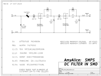
As the schematic diagram (below) indicates, AmyAlice consists of the ferrite bead, followed by a series cascade of two identical R-FTC-L-C passive filters. "R" is resistor R1, "FTC" is feedthru capacitor C1, "L" is inductor L1, and "C" is electrolytic capacitor C2. Each L-C pair contributes two poles to the lowpass filter, so AmyAlice as a whole contains a four pole passive lowpass filter. A four pole lowpass has a total of 80 dB of attenuation per decade, which is quite steep. Of course Murphy's Law dictates that the parasitic elements (parasitic C of the inductors; ESR and ESL of the capacitors; etc) diminish the attenuation at frequency extremes. AmyAlice is certainly not 80 dB per decade all the way from 1 Hz to terahertz! Oh no.
But wait, we have underestimated the attenuation. The 80 dB/decade figure doesn't include the extra attenuation provided by each of the feedthrough capacitors. Which is about 23 dB of attenuation at 100 kHz, and in excess of 60 dB at all frequencies between 7 MHz and 200 MHz. Wow. AmyAlice gets this attenuation boost twice, from the two FTCs. Also note: the 80dB/decade figure doesn't include the extra attenuation provided by the ferrite bead at the input. The bead adds further attenuation beyond about 2 MHz, see plot attached below.
So, putting it all together, approximately how much better is AmyAlice than the store filter PO89ZB? My own conservative (under)estimate is: 18dB greater attenuation. {math: log10( 18dB / 20 ) = 8x}. I estimate that AmyAlice is at least 8x better than PO89ZB, removing SMPS noise. However AmyAlice IS a bigger board, with 3 additional parts, and it "cheats" by using modern, surface mount components. To choose one versus the other, you will need to do your own cost-versus-benefit analysis. Or in some cases, an annoyance-versus-benefit analysis.
HOW TO BUILD YOUR OWN AmyAlice BOARD(S)
This project is not suitable for beginners or people who are completely lost without a Build Guide, assembly video, or tutorial. It requires SMD soldering which is a skill you develop by repetition and lots of practice.
You will need to order AmyAlice PCBoards from a PCB fab shop. I have written a quick Walkthrough that shows how to do this at the fab called "JLCPCB" (link); however the same principles and same steps are used at all fabs. Study the Walkthrough and I'm sure you will conclude: ordering PCBs is not mysterious, it's not complicated, and it's not at all frightening. It's exactly like buying anything else on an e-commerce website.
If you're feeling generous, you can order a bunch of AmyAlice PCBs, so you'll have plenty of extra boards left over, after you've built the AmyAlice(s) for yourself. You can offer these extra boards to other diyAudio members for free, or at your cost, or for a net profit to you. Your decision! Simply post a message here saying "7 extra AmyAlice boards available in UK/EU at price XXX, send me a PM if you want any". Or whatever your convenient shipping zone happens to be.
As of today, all of the components needed by AmyAlice are available and on the shelf at both US-Mouser and US-DigiKey. At least they are on 2023-Nov-02. If and when a part goes out of stock, you will have to download its datasheet and find the important characteristics, such as physical size, lead spacing, wattage, voltage rating, current rating, resistance, inductance, capacitance, etc. Then you will need to search for an equivalent part which matches those important characteristics, and is in stock at a distrubutor you are willing to buy from. If you feel incapable of this task; if it sounds more advanced than your current abilities as a DIY hobbyist; then perhaps you should wait and learn and grow, building other less challenging projects, before trying to buy parts for AmyAlice.
Will AmyAlice ever appear in the diyAudio Store? I don't know the answer with any certainty. I . DO . NOT . KNOW . However my own personal opinion is: AmyAlice probably won't become a Store product, because (A) the kit in the Store right now is selling very well, why mess with a good thing? and also (B) AmyAlice requires SMD soldering and the existing kit in the store does not. Since so many people reject SMD soldering completely, why swim against the tide? Let those few people who really, really want AmyAlice, order their own boards and source their own parts. Meanwhile the store happily sells 100 thru hole kits every month (??) -- it's a smooth running, well oiled machine by now. 22INDEX22
This is just my own opinion; I have ZERO visibility into the operations or plans of the Store. 22INDEX22
News (13 Dec 2023): a Member has created new PCB layouts for AmyAlice, some of which also include a capacitance multiplier circuit. You can find them in this thread: A2CMx: AmyAlice DC filter and cap multiplier for SMPS .
News (27 Feb 2024): a Member has created a new "slim" PCB layout for AmyAlice, and added an LED pilot light. You can find the board+Gerbers in this thread: AmyAlice SLIM - SMPS filter .
News (14 July 2024): a Member has created a new PCB layout for AmyAlice, which fits perfectly within a plastic enclosure. You can find the board+Gerbers in this thread: Compact SMPS filter using AmyAlice circuit design .
ANSWERS TO FREQUENTLY ASKED QUESTIONS
FAQ_01: Is it possible to assemble a pair of AmyAlice PCBs to implement a bipolar supply filter? For example, a filter that receives noisy ±24V inputs and produces quiet ±24V outputs? ANSWER: yes. See post #31 of this Forum thread.
FAQ_02: Is it possible to assemble an AmyAlice PCB that filters a negative power supply voltage, i.e., a voltage below ground? ANSWER: yes, see FAQ_01.
FAQ_03: If I build two AmyAlice filter boards and connect them in parallel, can I safely run 6 amperes (2 x 3 amps per board) through the parallel combination? ANSWER: no. See post #37 of this Forum thread.
FAQ_04: Has anyone created a "shopping cart" at DigiKey and/or Mouser, containing all components needed to build one AmyAlice PCB? ANSWER: yes, see posts #16 and #56 respectively, in this Forum thread.
_
There already exists a very nice DC filter for SMPS, as a project in the diyAudio store, which I encourage you to investigate. AmyAlice is similar to the Store filter, the differences being
- AmyAlice uses high performance, SMD-only, feedthrough capacitors. The thru-hole PCB in the store, does not
- AmyAlice includes a high performance ferrite bead to improve HF and VHF attenuation. The store PCB does not
- AmyAlice uses physically bigger inductors with 5x greater inductance than the inductors on the store PCB
- the Store PCB is smaller in size. See photo attached.
- the Store sells kits-of-all-parts. No such kits exist for AmyAlice, to my knowledge
THEN WHY BUILD AmyAlice AT ALL?
The DC filter kit in the store has always been implemented with thru-hole components only. A large number of builders are certain they cannot possibly succeed with surface mount parts, and quite a few more simply refuse to even try. For them, and everyone else, the all-thru-hole, zero-SMD store kit is available.
However, as Forum readers are well aware, there are lots of new electronic components which are offered ONLY in SMD packages. High volume electronics manufacturing is all-SMD in Y2023, therefore component suppliers meet their customers' needs with all-SMD parts. This is particularly true of new components, which, by the very definition of the word "new", do not exist in legacy thru-hole designs. The whole world has moved on to SMD assembly.
A couple of new, SMD-only components are now available, which enable much better performance (i.e. greater noise attenuation) in SMPS DC filters. These SMD parts cannot be used on the Store PCB, or any other must-be-thru-hole-only board. But they CAN be used on AmyAlice because AmyAlice allows SMD components.
One such SMD component is the 1.0 microfarad, 3-terminal Feedthru Capacitor sold by TDK. Its datasheet, and the attenuation plot from that datasheet, are attached below. AmyAlice uses the "2A105" model of Feedthru Capacitor; as you can see, it offers spectacular HF attenuation, even at 100 kHz. AmyAlice actually includes two of these, so its attenuation is spectacular-squared.
A second addition to AmyAlice is an SMD packaged ferrite bead from Wurth. The impedance curve of this bead is attached below; it rejects HF, RF, and VHF noise quite aggressively. The ferrite bead is the first series element in the AmyAlice cascade of filters.
As the schematic diagram (below) indicates, AmyAlice consists of the ferrite bead, followed by a series cascade of two identical R-FTC-L-C passive filters. "R" is resistor R1, "FTC" is feedthru capacitor C1, "L" is inductor L1, and "C" is electrolytic capacitor C2. Each L-C pair contributes two poles to the lowpass filter, so AmyAlice as a whole contains a four pole passive lowpass filter. A four pole lowpass has a total of 80 dB of attenuation per decade, which is quite steep. Of course Murphy's Law dictates that the parasitic elements (parasitic C of the inductors; ESR and ESL of the capacitors; etc) diminish the attenuation at frequency extremes. AmyAlice is certainly not 80 dB per decade all the way from 1 Hz to terahertz! Oh no.
But wait, we have underestimated the attenuation. The 80 dB/decade figure doesn't include the extra attenuation provided by each of the feedthrough capacitors. Which is about 23 dB of attenuation at 100 kHz, and in excess of 60 dB at all frequencies between 7 MHz and 200 MHz. Wow. AmyAlice gets this attenuation boost twice, from the two FTCs. Also note: the 80dB/decade figure doesn't include the extra attenuation provided by the ferrite bead at the input. The bead adds further attenuation beyond about 2 MHz, see plot attached below.
So, putting it all together, approximately how much better is AmyAlice than the store filter PO89ZB? My own conservative (under)estimate is: 18dB greater attenuation. {math: log10( 18dB / 20 ) = 8x}. I estimate that AmyAlice is at least 8x better than PO89ZB, removing SMPS noise. However AmyAlice IS a bigger board, with 3 additional parts, and it "cheats" by using modern, surface mount components. To choose one versus the other, you will need to do your own cost-versus-benefit analysis. Or in some cases, an annoyance-versus-benefit analysis.
HOW TO BUILD YOUR OWN AmyAlice BOARD(S)
This project is not suitable for beginners or people who are completely lost without a Build Guide, assembly video, or tutorial. It requires SMD soldering which is a skill you develop by repetition and lots of practice.
You will need to order AmyAlice PCBoards from a PCB fab shop. I have written a quick Walkthrough that shows how to do this at the fab called "JLCPCB" (link); however the same principles and same steps are used at all fabs. Study the Walkthrough and I'm sure you will conclude: ordering PCBs is not mysterious, it's not complicated, and it's not at all frightening. It's exactly like buying anything else on an e-commerce website.
If you're feeling generous, you can order a bunch of AmyAlice PCBs, so you'll have plenty of extra boards left over, after you've built the AmyAlice(s) for yourself. You can offer these extra boards to other diyAudio members for free, or at your cost, or for a net profit to you. Your decision! Simply post a message here saying "7 extra AmyAlice boards available in UK/EU at price XXX, send me a PM if you want any". Or whatever your convenient shipping zone happens to be.
As of today, all of the components needed by AmyAlice are available and on the shelf at both US-Mouser and US-DigiKey. At least they are on 2023-Nov-02. If and when a part goes out of stock, you will have to download its datasheet and find the important characteristics, such as physical size, lead spacing, wattage, voltage rating, current rating, resistance, inductance, capacitance, etc. Then you will need to search for an equivalent part which matches those important characteristics, and is in stock at a distrubutor you are willing to buy from. If you feel incapable of this task; if it sounds more advanced than your current abilities as a DIY hobbyist; then perhaps you should wait and learn and grow, building other less challenging projects, before trying to buy parts for AmyAlice.
Will AmyAlice ever appear in the diyAudio Store? I don't know the answer with any certainty. I . DO . NOT . KNOW . However my own personal opinion is: AmyAlice probably won't become a Store product, because (A) the kit in the Store right now is selling very well, why mess with a good thing? and also (B) AmyAlice requires SMD soldering and the existing kit in the store does not. Since so many people reject SMD soldering completely, why swim against the tide? Let those few people who really, really want AmyAlice, order their own boards and source their own parts. Meanwhile the store happily sells 100 thru hole kits every month (??) -- it's a smooth running, well oiled machine by now. 22INDEX22
This is just my own opinion; I have ZERO visibility into the operations or plans of the Store. 22INDEX22
News (13 Dec 2023): a Member has created new PCB layouts for AmyAlice, some of which also include a capacitance multiplier circuit. You can find them in this thread: A2CMx: AmyAlice DC filter and cap multiplier for SMPS .
News (27 Feb 2024): a Member has created a new "slim" PCB layout for AmyAlice, and added an LED pilot light. You can find the board+Gerbers in this thread: AmyAlice SLIM - SMPS filter .
News (14 July 2024): a Member has created a new PCB layout for AmyAlice, which fits perfectly within a plastic enclosure. You can find the board+Gerbers in this thread: Compact SMPS filter using AmyAlice circuit design .
ANSWERS TO FREQUENTLY ASKED QUESTIONS
FAQ_01: Is it possible to assemble a pair of AmyAlice PCBs to implement a bipolar supply filter? For example, a filter that receives noisy ±24V inputs and produces quiet ±24V outputs? ANSWER: yes. See post #31 of this Forum thread.
FAQ_02: Is it possible to assemble an AmyAlice PCB that filters a negative power supply voltage, i.e., a voltage below ground? ANSWER: yes, see FAQ_01.
FAQ_03: If I build two AmyAlice filter boards and connect them in parallel, can I safely run 6 amperes (2 x 3 amps per board) through the parallel combination? ANSWER: no. See post #37 of this Forum thread.
FAQ_04: Has anyone created a "shopping cart" at DigiKey and/or Mouser, containing all components needed to build one AmyAlice PCB? ANSWER: yes, see posts #16 and #56 respectively, in this Forum thread.
_
Attachments
-
 image_AmyAlice_RevB_schematic.png26.2 KB · Views: 3,151
 -
 AmyAlice_alone.jpg473.2 KB · Views: 3,058
 -
 Top_Copper_Plot.png7.7 KB · Views: 2,111
 -
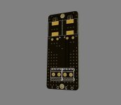
 Bottom.jpg258.8 KB · Views: 1,694
 -
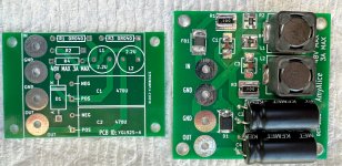 Comparison.jpg481.2 KB · Views: 1,883
 -
Gerbers_SMPS_AmyAlice_RevB.zip13.9 KB · Views: 413
-
 feedthru_graph.png26.4 KB · Views: 1,798
 -
 from_ferritebead_datasheet.png10.6 KB · Views: 2,692
 -
TDK_SMD_feedthru_datasheet.pdf129.1 KB · Views: 352
-
AmyAlice_RevB_Schematic.pdf23 KB · Views: 476
Last edited:

SMD…..Start Making Decisions. I’m off to the pcb house!
Thank you Mr Johnson.
Thank you Mr Johnson.
@Monk55 -- good on ya!! I sure do admire bravery and you are brave to try something new and different. Fantastic.
Awesome! Got a quick question, will more capacitance value = better filtering (lets consider nichicon uhw)?
If you are handy with second order differential equations (and their quick solution using Laplace Transforms), put that new and larger capacitance into the equations and calculate the damping ratio Zeta. Is it dangerously low?
If you've forgotten most or all of the aforementioned mathematics, I recommend you don't change the circuit design if you don't understand it thoroughly.
If you've forgotten most or all of the aforementioned mathematics, I recommend you don't change the circuit design if you don't understand it thoroughly.
Nice , thanks Mark, another great project.
Been pondering this RE your thru hole filter.....2 X smps, 2 X filter in series gives us a bipolar supply?
Been pondering this RE your thru hole filter.....2 X smps, 2 X filter in series gives us a bipolar supply?
I'm not, hence my question 🙂If you are handy with second order differential equations (and their quick solution using Laplace Transforms), put that new and larger capacitance into the equations and calculate the damping ratio Zeta. Is it dangerously low?
If you've forgotten most or all of the aforementioned mathematics, I recommend you don't change the circuit design if you don't understand it thoroughly.
@Brijac
Mark is saying that every component on this board is measured and used for more than one parameter, which is to say, specific to your inquiry, that the ESR of the capacitors is used in the equations as well as the capacity… so in simple terms, do not change anything.
This is not an audio-frequency filter where blindly throwing more capacitance at the filter will usually benefit. This is for high-frequency and to RF noise.
Last edited:
I understand what he said. I just sincerely asked a question as i've seen people increasing capacitance in his previous design. I don't doubt his ability, heck i use his p089zb everywhere in the house, i made semi smd version of it, and i'm glad he wen't and designes fully smd one.
Honestly, if you wanted even more filtration, after AmyAlice or P089ZB, you could build something resembling the RCRCRC filter Nelson has on ACP+. Lossy, yes, but filtration is also pretty darn good for simple parts. And would be a great place to use up various capacitors.

Last edited:
And the circuit of #13 has the ENORMOUS advantage of not requiring a Laplace Transform analysis because it has vanishingly small resonant peaking. If you can accept the I*R dropped voltage across R18-R21, it's an extremely viable option. It also gives you the opportunity to mount several expensive boutique capacitors for eye candy and bragging rights. But it will be physically bigger; four 1000uF caps need more room than two 470uF caps.
Last edited:
Nice , thanks Mark, another great project.
Been pondering this RE your thru hole filter.....2 X smps, 2 X filter in series gives us a bipolar supply?
I’ve used (an unreleased) Mark filter in a similar way. There’s no reason this wouldn’t work. The trick is reversing the polarized components, and then remembering that the reversed PCB will release smoke if used in a “standard” way. (So mark it clearly!)
@Brijac Very nice!! Please post photos when you have some built ! 🙂
@Monk55 Thank you!! I’ll use that cart to order things today. 😎
Last edited:
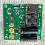
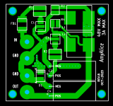
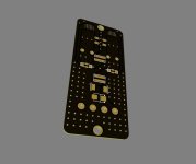
I encourage any potential builders who may feel a bit nervous about SMD soldering, to have a close look at the images attached to post #1 in this thread. Especially the Top_Copper plot from Gerber data, and the AmyAlice_alone photo of a finished board with all parts soldered in place.
Notice how large and roomy the component footprints are, with generous extra solderpad (copper) extending way beyond the component body. This gives you more room for, um, imperfect component placement and imperfect component rotation during soldering. The extra room also allows you to touch up the board with a standard pencil soldering iron and wire solder; there's plenty of clearance and plenty of PCB copper to fit both the iron and the solder wire.
In fact, every single component on the board you see here, was soldered with a chisel tip soldering pencil and wire solder. No stencil, no solder paste, no hot plate, no hot air rework blower, no reflow oven. Just a Hakko FX-888 fitted with (this bog-standard tip) and using (this unexotic wire solder). Of course you are free to solder your AmyAlice any way you wish, and I certainly do not claim a solder pencil is better than the others. It is merely an example of a very old-school soldering method that happens to work extremely well on AmyAlice. This PCB gives you enough room to try several different soldering options. Thanks to the spacious, roomy component footprints. Wasteful? I don't think so but others may disagree.
Further to the Digikey BOM in post #16 from Monk55 (thanks for that), I have just looked for the same list at Mouser - and you will find all parts in stock at cheaper prices $6.16USD as against $7.60USD at DK for 1 off pcb. Pricing becomes way cheaper at 10+ price point if you are making a few boards or perhaps combining or sharing with other members. The price of all components per board at the 10+ price point is $4.87 USD each to make 5 boards, a bargain really thanks to Mark, and as Jim has just said - a great intro to SMD soldering as well. 5 pcb's at JLCPCB are only $2.00 USD ($0.40 USD each) plus freight. So, $5.27 USD each for 5 finished boards plus the freight you choose for delivery from JLCPCB.
Last edited:
- Home
- Amplifiers
- Power Supplies
- AmyAlice: DC filter for SMPS, using 2 feedthru capacitors + SMD assembly. max 3A & max 48V