Honestly, if you wanted even more filtration, after AmyAlice or P089ZB, you could build something resembling the RCRCRC filter Nelson has on ACP+. Lossy, yes, but filtration is also pretty darn good for simple parts. And would be a great place to use up various capacitors.
View attachment 1230868
If I may slightly dip OT for a split second, how about this for a 2nd stage active filter? https://www.edn.com/feedforward-noise-cancellation-rejects-supply-noise/
Post #21 is Charles Wenzel's "Finesse" filter, which he placed in the public domain circa 2001. His website has been renamed a few times since then, here is what I think is the most current (link 1).
diyAudio member @Elvee applied Wenzel's Finesse concept to adjustable 3-pin voltage regulator ICs, giving the De-Noizator project here on the Forums (link 2). Another DIYA member uploaded Gerber CAD files of a PCB which includes transformer snubbers, bridge rectifiers, bulk filter capacitors, and two De-Noizer circuits {one for each rail}, to deliver bipolar regulated DC output: plusV and also minusV. That project goes by the name VRDN here on the Forums.
diyAudio member @Elvee applied Wenzel's Finesse concept to adjustable 3-pin voltage regulator ICs, giving the De-Noizator project here on the Forums (link 2). Another DIYA member uploaded Gerber CAD files of a PCB which includes transformer snubbers, bridge rectifiers, bulk filter capacitors, and two De-Noizer circuits {one for each rail}, to deliver bipolar regulated DC output: plusV and also minusV. That project goes by the name VRDN here on the Forums.

My worry with this filter is that it doesn't remove noise from the ground line - it assumes all the noise from the switcher comes out of only one terminal, which is assuming its internal ground inductance is zero... I'd suggest adding filtering symmetrically to both wires, so that it can remove both common-mode and differential-mode noise.
Please feel free to upload your own design including PCB Gerbers. Try not to introduce unwanted DC voltage drop between Protective Earth (inside the SMPS) and your filtered-ground output, when 3 amperes of DC load current are flowing. The inductors and the ferrite beads I've examined, have nonzero DC resistance. Some more than others.
Ordered boards and parts for 5 boards. I'm using the PO89ZB for my ACP+, ACA Mini, and some Raspberry PIs running RoPieee. I also have a RCRCRC ACP+ filer I was using with my FE22 until I replaced the PS with Ben Hah's. I might use it with the ACA Mini.
This hobby is fun with all the great ideas.
This hobby is fun with all the great ideas.
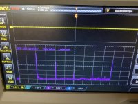
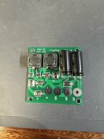
My smps power supply(90w laptop brick powering another buck-boost ) output looks like in the first attachment so I was thinking that a cap multiplier would be nice to have.
Could something like this work?
Edit: need them to power a nchannel vfet follower
Could something like this work?
Edit: need them to power a nchannel vfet follower
Attachments
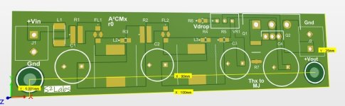

Congratulations @schultzsch your design looks good! I recommend you add one or more test points where you can attach oscilloscope ground clips (or multimeter black leads), and I also recommend you add test points so you can attach scope probes to (a) positive terminal of C3; (b) positive terminal of C4; (c) node Vfilt++ .
After you build it and connect it to audio gear, please let us know whether you are happy with the measured results AND the listening results! Good on ya.
edit- by the way, the actual 0.1 ohm, 2 Watt, 1% resistors are labeled ".100" -- check the photo attached to post #1. Your 3D render seems to show ".010"
Last edited:
Thanks Mark
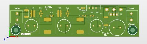
the footprint is for a different part, I have it correctly in the schematic. ERJ-D1CFR100U
I added the test points and via stitching. At this point if all good I will order the pcbs.
the footprint is for a different part, I have it correctly in the schematic. ERJ-D1CFR100U
I added the test points and via stitching. At this point if all good I will order the pcbs.
Attachments
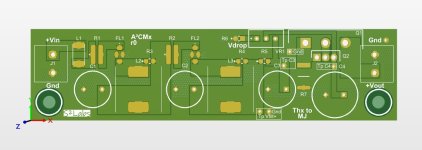
A Forum member told me about a bipolar power supply (switch mode), whose outputs he intends to filter using a pair of AmyAlice PCBs. One AmyAlice will filter the +15 volt supply rail, and the other AmyAlice will filter the -15 volt supply rail. The +15V board will be completely stock and standard, following post #1 of this thread exactly. The -15V board will be almost stock, the only change being: all three polarized components need to be reversed for a negative supply AmyAlice. The Zener diode and the two electrolytic capacitors need to be reversed. Schematic below. What used to be Cathode, now becomes Anode. What used to be Capacitor-Plus, now becomes Capacitor-Minus. Pretty evident when you look at the schematic.
It would be a very good idea to mark this negative-supply AmyAlice board with Dymo labels or Sharpie notes or colored paint, to make it crystal clear and OBVIOUS that it is not a normal (positive voltage) AmyAlice board. If you install an neg-AmyAlice board where a pos-AmyAlice board should go (or vice-versa), you're going to have a bad time. So don't do that. Make it highly visible and easily noticed, even by sleep-deprived, in-a-hurry, you. In the future.
_
Attachments

Last edited:
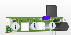
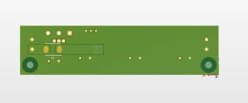
Speaking of AmyAlice, I had a chance to assemble one today, took a photo right before completion.
Lots of room on the PCB pads, everything soldered easily with a normal iron and good solder.

Lots of room on the PCB pads, everything soldered easily with a normal iron and good solder.
Right? Mine was very easy, used a normal iron and solder with good flux (Fire Metall), used a thin bit of blue painter’s tape to hol the component in place, and they soldered with no issues at all. Love it!
Agree….I just laid a big pink eraser on the teeny tiny…soldered one edge…yes used the fire metal, great solder!
Unfortunately the manufacturer's datasheets don't give you enough information to predict whether two AmyAlice boards in parallel, will perform as you might hope.
At DC, each AmyAlice board is just a resistor from in to out. Unfortunately, the components soldered on the two PCBs are not identical; there are manufacturing variances which increase or decrease the resistance of the resistors, the feedthru capacitors, the inductors, and the ferrite beads. Each AmyAlice board has seven resistors in series (ferrite bead ---> 0.1R ---> feedthru cap ---> inductor ---> 0.1R ---> feedthru cap ---> inductor) and so its total end-to-end resistance is the sum of seven random variables. Which means: the two AmyAlice boards are unlikely to have identical end-to-end resistances.
Which means: one AmyAlice board will conduct more of the load current, than the other AmyAlice board. The output current doesn't split equally between the two filter boards.
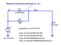
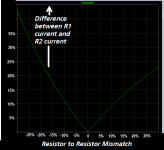
A picture of the situation is diagrammed below. "R1" represents an AmyAlice board {normalized to 1.0 units of resistance} and "R2" represents another AmyAlice. They do not have identical resistances; the mismatch between the two AmyAlice resistances is denoted "xx". For example, if the resistance mismatch is 5 percent then xx=0.05.
I've stepped the board1 vs board2 mismatch ("xx") to make the graph below. It says that if AmyAlice1 (R1) is 10% higher resistance than AmyAlice2, there is an 8% difference between the currents flowing in the two AmyAlice boards. And if AmyAlice1 is 10% lower resistance than AmyAlice2, there is an 11% difference between the currents flowing in the two AmyAlice boards.
Regrettably, since the datasheets don't include resistance tolerances or min&max values, about the only thing you can do is measure the in to out resistances of your two AmyAlice boards and check whether they are "close enough" in your judgement. Regrettably, this will require a somewhat sophisticated measurement apparatus with four point "Kelvin probes" to measure resistances in the neighborhood of 0.2 ohms. It can be done but not with a $75 multimeter from Amazon.
Things get better, of course, if you won't be running your pair of AmyAlice boards right at their maximum limits (3 amperes each). If your total load current is "only" 4 amperes then you can tolerate a bigger mismatch between the two AmyAlice boards, and still remain below 3 amps on the board with the lower resistance. Kelvin probe measurement + Ohm's Law + 9th grade Algebra will tell you the whole truth.
At DC, each AmyAlice board is just a resistor from in to out. Unfortunately, the components soldered on the two PCBs are not identical; there are manufacturing variances which increase or decrease the resistance of the resistors, the feedthru capacitors, the inductors, and the ferrite beads. Each AmyAlice board has seven resistors in series (ferrite bead ---> 0.1R ---> feedthru cap ---> inductor ---> 0.1R ---> feedthru cap ---> inductor) and so its total end-to-end resistance is the sum of seven random variables. Which means: the two AmyAlice boards are unlikely to have identical end-to-end resistances.
Which means: one AmyAlice board will conduct more of the load current, than the other AmyAlice board. The output current doesn't split equally between the two filter boards.
A picture of the situation is diagrammed below. "R1" represents an AmyAlice board {normalized to 1.0 units of resistance} and "R2" represents another AmyAlice. They do not have identical resistances; the mismatch between the two AmyAlice resistances is denoted "xx". For example, if the resistance mismatch is 5 percent then xx=0.05.
I've stepped the board1 vs board2 mismatch ("xx") to make the graph below. It says that if AmyAlice1 (R1) is 10% higher resistance than AmyAlice2, there is an 8% difference between the currents flowing in the two AmyAlice boards. And if AmyAlice1 is 10% lower resistance than AmyAlice2, there is an 11% difference between the currents flowing in the two AmyAlice boards.
Regrettably, since the datasheets don't include resistance tolerances or min&max values, about the only thing you can do is measure the in to out resistances of your two AmyAlice boards and check whether they are "close enough" in your judgement. Regrettably, this will require a somewhat sophisticated measurement apparatus with four point "Kelvin probes" to measure resistances in the neighborhood of 0.2 ohms. It can be done but not with a $75 multimeter from Amazon.
Things get better, of course, if you won't be running your pair of AmyAlice boards right at their maximum limits (3 amperes each). If your total load current is "only" 4 amperes then you can tolerate a bigger mismatch between the two AmyAlice boards, and still remain below 3 amps on the board with the lower resistance. Kelvin probe measurement + Ohm's Law + 9th grade Algebra will tell you the whole truth.
Attachments
Thanks! My take-away here is that the current hog sets the totaled amperage capacity of a two parallel board setup reaching the practical max when the hog gets to 3 amps.
Boards and parts ordered. This looks very approachable. I had one horrible experience in 2007 or so chasing a part around a board, but the large pads have convinced me along with some 'gravity' hold-down ideas i've seen on the web. Lining up 10 or so and really practising in a series of 1 to 1.5 hour sessions should get me up to confident. I bought a few extra parts to allow the floor to hide them while I can use others. I'm hoping this will get me up to 'Norwood' level as the the M2x stuff I have is calling more strongly.
- Home
- Amplifiers
- Power Supplies
- AmyAlice: DC filter for SMPS, using 2 feedthru capacitors + SMD assembly. max 3A & max 48V