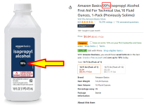

I've never seen any isopropyl above 90% in a store but I bought a quart of the 99% online a couple of years ago.
Soaking your PCB's in a covered container with enough IPA to cover the PCB is the lazy person's way. Then an old junky toothbrush to scrub it all off does the trick. (Rinse well, keep scrubbing with toothbrush)
Thanks, Mark for this design! I hope there's no issue if I poach the circuit and park it on the power input of some of my future boards?
Daniel
Thanks, Mark for this design! I hope there's no issue if I poach the circuit and park it on the power input of some of my future boards?
Daniel
For gleaming-clean PCBs use ultrasonic cleaner with this:
https://www.amazon.de/-/en/Oregon-Ultrasonic-Cleaning-Concentrate-Bottle/dp/B07X5NK3Z6
Some baking time in oven probably useful after cleaning to remove moisture. For best results first remove most flux with IPA and toothbrush.
https://www.amazon.de/-/en/Oregon-Ultrasonic-Cleaning-Concentrate-Bottle/dp/B07X5NK3Z6
Some baking time in oven probably useful after cleaning to remove moisture. For best results first remove most flux with IPA and toothbrush.
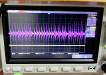
I tested the discrete component filter last night and it worked great .😛
Purple is the input,Yellow is the output.
Attachments
Last edited:
Please feel free to call your creation any name you like, as long as it's NOT "AmyAlice". AmyAlice includes no R050 resistor and no 1K resistor and no 0.1uF capacitor and CERTAINLY no toroidal common mode choke. AmyAlice has two inductors per rail (not four). AmyAlice includes a TVS, missing from yours. Whatever that circuit in #69 happens to be, it certainly isn't AmyAlice.
_
_
Last edited:
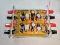
Yes, it's not "AmyAlice", I borrowed your circuit and made some modifications with the components I already had.
Thanks for sharing🙂
Thanks for sharing🙂
Thanks for a great intro into SMT. I've built 3 with more on the horizon, when parts arrive from Mouser.
Replaced 2 P089ZB (original SMPS) and the deference in sound is pretty stunning. Most notably in the ACA Mini amp. The sound dynamics increased beyond what I could have imagined possible.
Appreciate all you're education bits regarding SMT tech.
this is t he first board that is setup for the negative side of a power supply source. Waiting to build the positive side of the rail.
Congratulations @carlpsyd , glad you tried SMD and succeeded! Thanks for the listening evaluations as well.
I think you may want to double check whether you remembered to rotate TVS Diode "D1" on the Negative Supply Filter PCB shown in post #73. The diagram showing the proper rotations is attached to post #31.
I think you may want to double check whether you remembered to rotate TVS Diode "D1" on the Negative Supply Filter PCB shown in post #73. The diagram showing the proper rotations is attached to post #31.
Thanks for the heads up.
Double checked with a meter and got it going in the correct direction for negative supply filtering.
Double checked with a meter and got it going in the correct direction for negative supply filtering.
- Home
- Amplifiers
- Power Supplies
- AmyAlice: DC filter for SMPS, using 2 feedthru capacitors + SMD assembly. max 3A & max 48V