I don't look at the empty spaces, rather at "the space" required by a wave, call it sinus or close or whatever. Empty spaces are more "occurences" to me here, whatever the reason.
2us reading (very approx again) gives 500kHz frequency, simple maths.
Should your unit (?) have identified 666kHz as frequency, then trust rather that figure than mine from a reading on a phone from work to the airport GLOL
My point was just to quickly question the mentioned 50kHz... I believe I see probs rather at 0,5MHz ish and 1MHz ish again.
Whatever, AmyAlice is your friend., that was the initial question, wasn't it?
Good luck
Claude

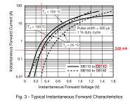
This single electronic component costs USD 0.28 at DigiKey (qty=1) and cuts your noise amplitude in half. Its voltage drop at 320 mA is about 300 mV , thus you still have 6.2V more voltage drop which you can divide up among subsequent series filters.
_
_
Attachments
Got it. As seen, yes, 0.5MHz (666kHz) and 5.1MHz emerges from 5us and 500ns respectively.My point was just to quickly question the mentioned 50kHz... I believe I see probs rather at 0,5MHz ish and 1MHz ish again.
Diode Schottky Barrier SB140This single electronic component costs USD 0.28 at DigiKey (qty=1) and cuts your noise amplitude in half. Its voltage drop at 320 mA is about 300 mV , thus you still have 6.2V more voltage drop which you can divide up among subsequent series filters
If we suppose 1A current we have 0.4V drop and we can put up to 16 diodes in series.
But while I can reverse eng. your snap of datasheet, I'm not confident on the layout of the filter. I simply put 1~16 diodes in series, forward bias, on the positive terminal that go to Vin? Seems so.
Thanks guys
Last edited:
Don't know why you mention 5MHz, but just as a note 5us gives 200kHz rather than 500kHz.
I guess though you got the point somehow...
I guess though you got the point somehow...
Im referring to H time not the duration of the sinus.
Have you seen this image?
In 5us my DSO2512G says 666kHz
In 500ns it says 5.11Mhz
I got your point and obv is right. We need to suppress a noise of 666kHz, while we don't care if it appears every 4 squares ~20us (~50kHz inverter switching frequency).
It could be constant noise or 1 time per minute noise, but it is still 666kHz freq and that is what I aim to suppress.
But last measure at 500ns report 5.11MHz. Probably since the DSO can make more sampling and so seeing deeper in the wave. Or is it a resonant in the 666kHz wave?
Sorry for my newbie questions
Last edited:
A diode (and subsequent filter capacitances) removes the bottom half of the noise waveform. But you can only remove the bottom half once. After it's been removed you can't remove it again. So there's no noise removal benefit if you try adding a second or third or additional diode after the first one. Sixteen diodes is a bad idea.
Sixteen ferrite beads, in series, on the other hand . . . . I'll let people offer their own advice about that.
Sixteen ferrite beads, in series, on the other hand . . . . I'll let people offer their own advice about that.
I got it about diode, it is logic. I wansn't thinking about how it would operate. I missunderstood your "subsequent series filters" referring not to diodes but to LC or similar filters.A diode (and subsequent filter capacitances) removes the bottom half of the noise waveform. But you can only remove the bottom half once.
Since capacitor filter would also operate on bottom half wave, my last possibility is L filtering.
I investigated feedthru caps (never heard before) and C, LC, Pi, T versions.
In my case I could create it on 70mmq wire, stripping the pvc off (or using as cap insulator), putting an adequate insulator, and then an outer conductive layer, grounded (C type). Add 1 or 2 ferrite beads (LC, Pi or T type).
And so we are talking about ferrite beads (16 beads joke apart 😆 or are you serious?)
Can I wrap copper wire around the 70mmq wire and then ground (12V GND or even better EARTH) one ore both ends? It should act as a ferrite beads with the advantage of discharging to ground/earth.
And if I wrap and counter wrap with the same wire, then GND/EARTH?
I think I will experiment a bit.
Here a suggestion of a vendor of ferrite beads. Beads... beads everywhere
Diode doesn't work. Maybe is fake? It is from aliexpress.A diode (and subsequent filter capacitances) removes the bottom half of the noise waveform. But you can only remove the bottom half once. After it's been removed you can't remove it again. So there's no noise removal benefit if you try adding a second or third or additional diode after the first one. Sixteen diodes is a bad idea.
Sixteen ferrite beads, in series, on the other hand . . . . I'll let people offer their own advice about that.
0.1,1,10,100uF 1206 SMD parallels caps on Vin/GND of Arduino have not solved (shortest path possible).
Isolated optocoupled 7-80V AC/DC to 5VDC SOLVED the issue on Arduino side but OBV not the general ripple on 12V rails.
If I will build AmyAlice I will report my experince. Since that, thanks for support guys 🙂
I'm calling out on this assertion - forward biased diodes act rather like a low value resistance in parallel with substantial capacitance - not going to filter out RF much at all. RF switching with PIN diodes uses this property explicitly - forward biased acts as low-loss RF conductor, reverse bias acts as very small value capacitor (for a PIN structure at least). Ordinary PN diodes are similar but with higher off-capacitances and not very linear (with strong RF).
Filtering power lines is difficult partly because the impedance is ill-defined and probably changing, and also because most magnetic materials saturate readily reducing their effectiveness in chokes/inductors when under load. A ferrite bead rated at say 300 ohms at 100MHz with a max current of 5A may only have 50 ohms of loss at that full current...
You want high values of capacitance with low ESL to shunt, and high values of broad-band inductance with low ESR / and low leakage capacitance and high saturation currents to be in series... And hopefully there is somewhere for the noise energy to dissipate as quality C and L only push the noise elsewhere rather than absorb the energy. It takes effort to do a good job as this thread testifies...
Over time things will be easier as SMPS's are going up in frequency as technology advances, making their artifacts easier to filter with smaller filter components. Hopefully it means more SMPS's which are low noise out of the box, needing no external filtering.
I've read that 1206 SMD capacitor are the best compromise for ESL since no leads reduce inductance path. I've connected between Vin and GND pins (look at photo) so the shortest path possible BUT the spikes are so BIG (2.5-8Vpp) that I doubt they could properly help.You want high values of capacitance with low ESL to shunt
Indeed. Thanks for the clarification.It takes effort to do a good job as this thread testifies...
Well, new diodes added to the collection 😆 Yes now you say that I totally misunderstood the behavior under RF.forward biased diodes act rather like a low value resistance in parallel with substantial capacitance - not going to filter out RF much at all.
It blocks reverse current (negative half wave) at lowest frequencies while going up to RF these freq bypass the component because the "equivalent parallel capacitance".
Now since inverter pull up to 250A... I doubt ferrite bead could handle that.
Feedthru capacitor can be replicate with a ferrite bead shunted to GND? Could be effective? I doubt.
As said, this is very hard task probably not required/possible to be solved. The inverter should be redesigned.
Just noticed I built my AmyAlice versions with P6SMB68A (so a 68V unidirectional TVS) per BOM without further thinking while I only build them with either a 5V or a 12V Meanwell module. So the 68V TVS does not really protect the 5V/12V load this way. This while having many P6SMB10CA (bidirectional but that does not hurt) in stock that would not be optimal but still of better use for the 5V version 🙂
Maybe it is a good tip for builders to use a lower value TVS when having lower output voltages. Can't recall I read such.
Maybe it is a good tip for builders to use a lower value TVS when having lower output voltages. Can't recall I read such.
Last edited:
Unidirectional TVS is preferred since it also protects against input polarity errors: (+) and (-) inputs reversed. This error condition forward biases the TVS "diode" and activates the short circuit current limit of the SMPS, while clamping the reverse voltage to a small and less harmful value. Low reverse voltage protects the polarized electrolytic capacitors, and the SMPS short circuit limiting alerts the user that something is very wrong.
Builders who really know what they are doing, can of course substitute different parts in whichever positions they like. It would be wise to label the board "DON'T USE WITH VIN > XXX VOLTS," perhaps on the bottom side, to caution future owners of the equipment that the top silkscreen text "MAX 48V" is not true for this particular AmyAlice.
Builders who really know what they are doing, can of course substitute different parts in whichever positions they like. It would be wise to label the board "DON'T USE WITH VIN > XXX VOLTS," perhaps on the bottom side, to caution future owners of the equipment that the top silkscreen text "MAX 48V" is not true for this particular AmyAlice.
Yeah I really know what I am doing as it is IRM20 in 5 or 12V and AmyAlice integrated so a complete PSU. The TVS will not ever see input polarity errors as connections can not be manipulated. Only severe overvoltage will trigger the 68V TVS but the load will definitely not survive. Bidirectional TVS in lower values adapted to the output voltages will protect against whatever polarity the surge voltage has and the load probably survives.
A P6SMB6.8CA for the 5V and P6SMB15CA for the 12V version seem more optimal and a useful protection of sensitive loads. It is use outside the standardised 48V but possibly useful info to others as the 68V TVS will otherwise never see action except when lightning strikes 😉
A P6SMB6.8CA for the 5V and P6SMB15CA for the 12V version seem more optimal and a useful protection of sensitive loads. It is use outside the standardised 48V but possibly useful info to others as the 68V TVS will otherwise never see action except when lightning strikes 😉
Last edited:
- Home
- Amplifiers
- Power Supplies
- AmyAlice: DC filter for SMPS, using 2 feedthru capacitors + SMD assembly. max 3A & max 48V