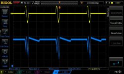
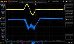
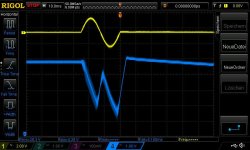
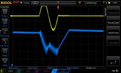
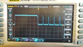
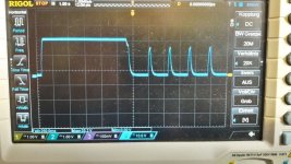
i did a test at my class D journey and test the over swing at a TPA3255 chinese amp 2018. generally the SMPS should go in hick up mode if the current exceed the start up current. (pip pip...you can hear that).
big caps:
additionally if you use a big cap , e.g. 10mF or 33mF you will have a big overshoot. this is because if you "request a big current by an amplifier" you get about 5V more at voltage on scope. instead of your adjusted voltage. so that means that the regulated internal circuit have problems with this big cap. that can shoot the caps on the amp pcb.
i remember that XRK did a trick if he use a SMPS and use a CRCRC like nelson did at the ACP. if you have too much ripple voltage from your SMPS you can use a CRCRC and use smal lytic caps for that.
kr chris
Attachments
-
 LRS150-24_40hz_4Routput_1Cycle_200msperiode_800mVrms input burst_originamp_2x1000uF_scope on a...jpg74.6 KB · Views: 69
 -
 LRS150-24_40hz_4Routput_1Cycle_200msperiode_800mVrms input burst_originamp_7x4700uF_crc_scope ...jpg75 KB · Views: 73
 -
 LRS150-24_40hz_4Routput_1Cycle_200msperiode_800mVrms input burst_originamp_7x4700uF_crc_scope ...jpg73.4 KB · Views: 64
 -
 LRS150-24_40hz_4Routput_1Cycle_200msperiode_1300mVrms input burst_originamp_2x1000uF_scope on ...jpg73.2 KB · Views: 63
 -
 LRS150-24_40hz_4Routput_1Cycle_200msperiode_1300mVrms input burst_originamp_7x4700uF_crc_scope...jpg73.2 KB · Views: 84
Last edited:

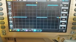
hick up tests:
Attachments
-
 LRS150_24_12mF_2ohms_Hickup.jpg116 KB · Views: 64
 -
 LRS150_24_12mF_2ohms_Hickup.jpg72.4 KB · Views: 63
 -
 LRS150_24_33mF_2ohms_Hickup.jpg75.4 KB · Views: 74
 -
 LRS350_36_12mF_2ohms_Hickup.jpg69.6 KB · Views: 69
 -
 LRS150_24_nocaps_2ohms_Hickup.jpg74.2 KB · Views: 60
 -
 LRS350_36_no caps_2ohms_Hickup.jpg73.9 KB · Views: 69
I'm using two similar SMPS (LRS-150-24) with capacitor multipliers with 2x 22,000uF capacitors each on my M2. And no adverse effects. It switches on every time without any complaints from the SMPS.
Note this was the test setup. It's all now built into a decent enclosure.

Note this was the test setup. It's all now built into a decent enclosure.
I assume the cap multiplier would help control the inrush current to the caps?
Maybe not though - as the big caps are before the multiplier !!
Maybe not though - as the big caps are before the multiplier !!
@Skylar88, are there gerber files here somewhere for that cap multiplier board - looks like a prasi design pcb to me. Would like to get hold of these, thanks.I'm using two similar SMPS (LRS-150-24) with capacitor multipliers with 2x 22,000uF capacitors each on my M2. And no adverse effects. It switches on every time without any complaints from the SMPS.
I found the info on those dual cap mult. pcb's.
I am still puzzled why the 22,000uF input caps on the cap mult. pcb's have no effect on the LRS SMPS - after all they are sitting directly on the SMPS output. I will take you word they are fine however - will try this for myself.
Can I ask - how does your M2 sound with this PSU setup?
I am still puzzled why the 22,000uF input caps on the cap mult. pcb's have no effect on the LRS SMPS - after all they are sitting directly on the SMPS output. I will take you word they are fine however - will try this for myself.
Can I ask - how does your M2 sound with this PSU setup?
@gary s Ok, so you found the Gerbers.
I'm really happy with the way the M2 (teabag's boards) turned out with the smps PSU + cap multipliers. It sounds great.
There are some pictures in post #3,535 of the M2 thread.
I'm really happy with the way the M2 (teabag's boards) turned out with the smps PSU + cap multipliers. It sounds great.
There are some pictures in post #3,535 of the M2 thread.
Hi Gary,
I use a similar setup (pair of switchers and capMx’s), the slow ramp up of the capMx keeps the SMPS from entering ‘hiccup’ mode at startup.
I use a similar setup (pair of switchers and capMx’s), the slow ramp up of the capMx keeps the SMPS from entering ‘hiccup’ mode at startup.
as i learned here in the forum.
the SMPS with CAPX are fine for class A amps. the current setup at a CLASS A amp is "easier" to handle with normal SMPS+capx
chris
the SMPS with CAPX are fine for class A amps. the current setup at a CLASS A amp is "easier" to handle with normal SMPS+capx
chris
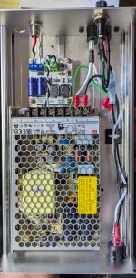
Started practicing my smd soldering for my F5M with smps similar to @birdbox
Blue tape pcb’s will be for the negative rail.
Those pads are nice and big for first time SMD soldering… more to follow.
Eventually I plan to use an AmyAlice for every piece in my system that uses smps… ACP+, DAC, Wim mini and el cheapo phono pre-amp.
Best,
Jose
The in/out holes are very big. What's the intention with these. Just cables (3A?) or a connector of sort?
//
//
Hello, I have kind of a newbie question:
I am trying to size an appropriate smps to use in a project. Can the output A of the smps be higher than 3A to the input of the AmyAlice board. I understand the 3A max on the output supply, but was not sure of the input from the smps.
Thanks,
MM
I am trying to size an appropriate smps to use in a project. Can the output A of the smps be higher than 3A to the input of the AmyAlice board. I understand the 3A max on the output supply, but was not sure of the input from the smps.
Thanks,
MM
Amps get drawn, not pushed.
So, not matter what amp capability the smps has, just make sure whatever you connect to the output of the AmyAlice filter doesn't draw more than 3A.
So, not matter what amp capability the smps has, just make sure whatever you connect to the output of the AmyAlice filter doesn't draw more than 3A.
yes its correct what Skylar88 wrote. Mark wrote here somewhere that at more then 3A the coils get saturated(DC current) and no more "filtering" of the higher frequencies works then.
chris
chris
Hello, I have kind of a newbie question:
I am trying to size an appropriate smps to use in a project. Can the output A of the smps be higher than 3A to the input of the AmyAlice board. I understand the 3A max on the output supply, but was not sure of the input from the smps.
Thanks,
MM
Hello,
The easiest way to avoid any problems is to double the power required.
If you need for example, 12V at 2A, or 24W, use a AC-DC power supply that outputs 50W. It will remain cold, the voltage will not change even in the event of a current spike and the ripple will stay low.
Stef.
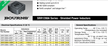
The datasheet of the SRR1280A-100M shows a saturation current of 6.3A, well more than 3A.
I presumed the limit was due to either the current capacity of the traces or R1 / R3. For example, for 4A,
Voltage drop 0.1 x 4 = 0.4V
Power 0.4X 4 = 1.6W which is too close to 2W.
Perhaps Mark could let us know.
ray

I presumed the limit was due to either the current capacity of the traces or R1 / R3. For example, for 4A,
Voltage drop 0.1 x 4 = 0.4V
Power 0.4X 4 = 1.6W which is too close to 2W.
Perhaps Mark could let us know.
ray
Attachments
I received this question recently, would anyone like to offer their experience, advice, opinion, or suggestions? I think it's best to encourage everyone to participate in the discussion and contribute ideas & thoughts if they wish. That's why the Forums exist, after all.
Can I series connect 2 kits of AmyAlice Vout of kit 1 goes to Vin of kit 2. Any pros and cons of doing it? I tried this scheme to my Aca mini using diyaudio store filter kit and running.
- Home
- Amplifiers
- Power Supplies
- AmyAlice: DC filter for SMPS, using 2 feedthru capacitors + SMD assembly. max 3A & max 48V