I received and stuffed some boards.
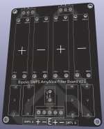
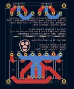
The big bipolar smps board looks great and will be a lot tidier than terminal blocks connecting 2 smps’s together and can be used with a single +0- supply. Each rail has its own fuse and filter.
I also made some 3d printed daughter board holders. It took 3 tries to get the size correct. I used PLA plastic to print them so not that strong, I wouldn’t be able to install and remove the boards too many times before it fails.
If anyone is interested in these I will post the gerbers and 3d models.
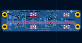
I also messed up the silkscreen on the daughter boards. I was lazy in KiCAD, just changing a reference to silkscreen and that doesn’t work. Worked that out and corrected it.
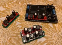

Beautiful! The red and black boards certainly do stand out.
Maybe you might someday decide to put these "condoms" over the fuse holders, so the live AC mains voltage on the blades is not exposed: Keystone Link . Mouser sells them.
Maybe you might someday decide to put these "condoms" over the fuse holders, so the live AC mains voltage on the blades is not exposed: Keystone Link . Mouser sells them.
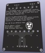
Thanks Mark. What live mains ac? Little covers would be safer with 48v rails. Will test the boards then post the gerbers and 3d models. Should get it done within the next week or so. Already sorted the silkscreen issue. Also changed the mounting holes on the main board from 77mm x 110mm to 80 x 110mm (nicer round numbers). Added some circles so the polarity can be written. Added some info on the back too. If I should change anything let me know.


D'oh!! I see glass cartridge fuses, I immediately think "AC mains!" but of course AmyAlice doesn't actually connect to the mains. Derp. You'd think I'd know that, I was actually in the room when the very first AmyAlice board was soldered and tested. Sorry for the careless mistake.
I've got some AmyAlice boards built up for stereo dual rail SMPS PSU. Soldered up great with the big ol' pads and ENIG finish.
Thanks Mark for the great design!!!
Parts layed out for two boards.

Here they are before cleaning flux off below.

Cleaned up and ready to mount in chassis.

Thanks Mark for the great design!!!
Parts layed out for two boards.
Here they are before cleaning flux off below.
Cleaned up and ready to mount in chassis.
It looks like I might have screwed up my orientations if I plan to use two of these AmyAlice for V- (negative) rail filtering. Before I go desoldering and flipping the two caps and the zener, I'm hoping someone can confirm. My plan is to use these for an F5m build with two SMPS (Meanwell LRS-150-24) and have individual AmyAlice filters on each rail output (four total AmyAlice for the two amp PCBs). Below is the schematic from @lhquam I planned on following for the wiring scheme.
If I flip the electrolytic caps and zener for the negative rails, I presume the wiring below is no longer correct, or am I getting mixed up? I may be going cross-eyed here.

If I flip the electrolytic caps and zener for the negative rails, I presume the wiring below is no longer correct, or am I getting mixed up? I may be going cross-eyed here.
I think that diagram in post #187 probably does more harm than good.
Why?
Because in includes two very different boards with very different behaviors, yet both are drawn using the same symbol "Filter".
DON'T DO THAT.
Instead redraw the diagram with two different symbols that have different names: REDfilter whose schematic is attached to post#1 of this thread, and BLACKfilter whose schematic is attached to post #31 ... as member @birdbox linked above.
REDfilter has two output pins, named OUTPOS and GND. BLACKfilter has two output pins, named OUTNEG and GND.
From top to bottom, the new diagram will have two BLACKfilters, then the ground isolation thermistor, then two REDfilters.
And the crucially important detail is: all four GND outputs of all four filters, are connected to the Star GND. You need a diagram which explicitly shows the GND connections. And oh by the way it will also explicitly show that OUTPOS goes to places which expect positive voltages (above ground), and OUTNEG goes to places which expect negative voltages (below ground). Ambiguity has been exterminated.
* a famous joke told by an ancient comedian called Henny Youngman: "I said to my doctor, I said hey doc it hurts when I do this! Doctor says, DON'T DO THAT."
Thanks Mark!!!
I'll spend some time trying to replicate, redraw, and tweak based on what I know now. Thank you! Hopefully my efforts will help others down the road.
I'll spend some time trying to replicate, redraw, and tweak based on what I know now. Thank you! Hopefully my efforts will help others down the road.
The schematic in post #187 is correct - just the terminology around the Pos and Neg Amy Alice Filter boards should be clearer as Mark has pointed out in his post. You have +DC, -DC and GND connections from all 4 filter boards to worry about. As well as reversing the 3 components on what will be your NEG filter boards.
At the beginning of this year I got to the point that I needed the filtering of A2CMX, its slow startup feature offered by the cap mx but also an extra negative rail. For the negative rail I could have added another power supply which may have gotten expensive in some cases so I opted for somethig else, an isolated dcdc converter.
More can be found here.
More can be found here.
Here's what I came up with for a drawing of a dual rail SMPS power supply with quad AmyAlice filtering. I've flipped the caps and diode on the two AmyAlice boards for the negative rail. I think this is correct and I'm hoping folks can either confirm or deny the accuracy of the wiring scheme including the star ground.

Do you have plans for any added capacitance between AmyAlice and F5m boards (or between SMPS and AmyAlice)? I do not know whether it would be needed, but extra filter or reservoir caps are commonly included btw SMPS and the amp. That is, if the SMPS can handle the load (some do not like it at startup, but I believe Meanwell LRS are agreeable). Sorry for the monkey wrench. 
I applaud what you are doing!

I applaud what you are doing!
@birdbox - Since the boards could (for a dolt like me) be easily confused, I'd suggest marking them. I'd mark mine in a way that future me would have a VERY low likelihood of swapping "positive" AmyAlice boards with "negative" AmyAlice boards. That's only if they may be reused in future projects... or just as a precaution.
Congratulations @birdbox your drawing in #193 looks 100% correct to me. I can see that the electrolytic capacitors have been flipped and I'll take your word that the TVS protection diodes are also flipped, that's hard to see in the photos. Great job!
+1 @ItsAllInMyHead. I printed out small labels and slapped them across the caps to make clear the polarity of each completed board.
You might have to be a bit careful with that. Most SMPS will tolerate a smallish cap value on the output (you would have to check datasheets and many times that is confusing) - this small value cap would really serve no purpose for a class A amp PSU.Do you have plans for any added capacitance between AmyAlice and F5m boards (or between SMPS and AmyAlice)? I do not know whether it would be needed, but extra filter or reservoir caps are commonly included btw SMPS and the amp. That is, if the SMPS can handle the load (some do not like it at startup, but I believe Meanwell LRS are agreeable). Sorry for the monkey wrench.
I applaud what you are doing!
- Home
- Amplifiers
- Power Supplies
- AmyAlice: DC filter for SMPS, using 2 feedthru capacitors + SMD assembly. max 3A & max 48V