Jack, it's much easier to use spare pcb's to fix thr one to be soldered in place, then use stencil on top, and fix with tape. That way, entire surface is on the same level, and stencil won't move.

Thank you everyone for the tips and suggestions. My plan for AmyAlice is to solder the SMD components in a reflow oven I am trying to set up. I'm using toaster oven, digital thermometer and timer to try and replicate the reflow curve. Could be an epic fail, but it seems surface mount is the future, and my eyesight and shaky hands make handsoldering a real challenge. Maybe if it turns out I'll post a pic.
I used a small non-stick frying pan, a small heating element, solder paste, and a little hot air. Worked like a charm, only had to touch up a couple of crooked parts. Soldered the inductors by solder iron.
Most of my smd work is done with an iron unless there are a lot of them little buggers😉.
MM
Most of my smd work is done with an iron unless there are a lot of them little buggers😉.
MM
are these measures been made with a spectrum analyzer ? Is there a way to make some similar "before and after" measures with my DSO (SIGLENT SDS1202X-E)?Here's some "before" and "after"Amy doing her thing on an HP Printer 32V 2.5A power supply. Note that the scale on the "after" is 2mV/div vs 20mV/div for the "before"
Last edited:
are these measures been made with a spectrum analyzer ? Is there a way to make some similar "before and after" measures with my DSO (SIGLENT SDS1202X-E)?
The TDSO2204 is just a Siglent scope made for Teledyne. When you have the waveform you've been looking for, hit the RUN/STOP button to freeze-frame, then PRINT to a memory stick. The TDSO2204 has arbitrary waveform generator which is very helpful.
You should have cursor selection on yours to measure the period of the pulses.
Question for Mark Johnson:
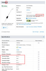
The SCP6SMB68AT3G TVS diode is out of stock at DigiKey and low stock at Mouser. It's also marked "not for new designs" at DigiKey.
Would the SZP6SMB62AT3G (listed as 53V working voltage) TVS diode (lots of stock, both vendors) be a usable substitute?
The SCP6SMB68AT3G TVS diode is out of stock at DigiKey and low stock at Mouser. It's also marked "not for new designs" at DigiKey.
Would the SZP6SMB62AT3G (listed as 53V working voltage) TVS diode (lots of stock, both vendors) be a usable substitute?
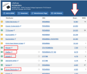
Thanks, Mark. I actually had to also drop the trailing T3G and search only for the P6SMB68A number to return valid results on Mouser's site. This device is in stock from multiple manufacturers as well as Littlefuse when searched for under its simplified generic number.
It turns out if you sub-filter for 68V in the Mouser search engine you only get the one number SCP6SMB68AT3G. That's because it is actually a 58.1V working voltage device in all the device search specs but that one device, which is missing the working voltage spec. And, it is listed as a 68V device in all of the device descriptions.
It turns out if you sub-filter for 68V in the Mouser search engine you only get the one number SCP6SMB68AT3G. That's because it is actually a 58.1V working voltage device in all the device search specs but that one device, which is missing the working voltage spec. And, it is listed as a 68V device in all of the device descriptions.
It's the SMD brother of the thru-hole TVS used in the thru-hole SMPS filter board which is sold in the diyAudio Store.
Fortunately it keeps quiet and does not conduct at the max permitted voltage rating of AmyAlice: 48 volts. Only when there is a surge / overload / hookup-error condition.
_
Fortunately it keeps quiet and does not conduct at the max permitted voltage rating of AmyAlice: 48 volts. Only when there is a surge / overload / hookup-error condition.
_
Attachments

Great boards, built already 4 of them. 3 are filtering B1 Nutubes (1 from me and 2 for friends), and I couldnt resist and will put one into a small Modushop Galaxy case to filter my Thorens Wall Power supply 😎 That way I can set it up next to my newly built Pearl 3 and keep a clean look.
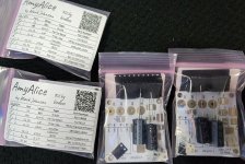
I have a bunch of AmyAlice boards for dirt cheap in the swap meet if anyone is interested. I also have all the parts for a number of full kits I made up. Eventually I'll also solder some boards up for folks who aren't able to do the solder work themselves for whatever reason.

I was so impressed with how this circuit works on @N Brock 's F5m Redux, that all of my SMPS projects are going to get an AmyAlice filter. Amazing design!
Thank you for your generosity Mark!
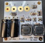
- White boards
- EING Finish
- 2oz outer copper
- 2.0mm board thickness
I was so impressed with how this circuit works on @N Brock 's F5m Redux, that all of my SMPS projects are going to get an AmyAlice filter. Amazing design!
Thank you for your generosity Mark!
Attachments
Last edited:
Y'all, those are some BEEFY circuit boards. Extra thick epoxy fiberglass, double thick copper, gold plated pads. Anybody who wants a rough, tough, macho, Heavy Duty AmyAlice - - - - here it is!
Congratulations @birdbox and thank you for your generosity.
Congratulations @birdbox and thank you for your generosity.
I used the AmyAlice filter on my latest build, a Holy Grail Follower amp. I put the bipolar SMPS filter on the amp PCB and wish I hadn't. I should have had it on separate boards so I could have a filtered PSU to use with other projects.


I designed this and will probably get some boards made soon. 4 AmyAlice filters mount on the main board with brass M2 standoffs, each has a fuse (the brown blocks). The 5-way screw terminal is for connecting the 2 SMPS and also has an Earth connection with an NTC-60 (the white block). The 2 3-way screw terminals are the positive and negative rail supplies. Using a board like this will also help with messy wires. Both SMPS will need their own Earth connections.
I designed this and will probably get some boards made soon. 4 AmyAlice filters mount on the main board with brass M2 standoffs, each has a fuse (the brown blocks). The 5-way screw terminal is for connecting the 2 SMPS and also has an Earth connection with an NTC-60 (the white block). The 2 3-way screw terminals are the positive and negative rail supplies. Using a board like this will also help with messy wires. Both SMPS will need their own Earth connections.
Very Nice!! You could consider ordering your little "diving board" daughter cards in two different colors of epoxy fiberglass, perhaps half of the total PCB quantity as red PCBs and the other half as black PCBs. Then stuff and solder the red PCBs so they are positive-hot, negative-ground. . . . . followed by the black PCBs stuffed and soldered as negative-hot, positive-ground. Now you can tell at a quick glance whether the proper daughter cards are arrayed onto the motherboard in the correct order. Red, Black, Red, Black.
Great idea Mark. The daughter boards are very cheap to get made and sent to me. I was just going to get 10, now I will get another 10 in a different colour too! I have a +- on the Vin that I was going to Sharpy to indicate the polarity. I will post the Gerber's and BOM when I have tested the design. I will also design a 3D printed mount/enclosure for the daughter boards when used on their own.
I ordered 10 red and 10 black daughter boards. Also 5 black main boards. I will be adding bipolar AmyAlice SMPS filters to my AlephJ and XA252. The XA252 sounds amazing as it is, not sure if it can get any better!

- Home
- Amplifiers
- Power Supplies
- AmyAlice: DC filter for SMPS, using 2 feedthru capacitors + SMD assembly. max 3A & max 48V