I posted this without reading through the whole thread. I did not mean to call this an "AmyAlice". My documents all refer to this as an "SMPS AAF".
Mark: Do I need to post this as a new thread and have you link to it?
Mark: Do I need to post this as a new thread and have you link to it?
First of all thank to @Mark Johnson for this very useful project. I started using it from very beginning when Mark published it and I’m very satisfied.
I’ve also used it in some very low power demanding device where I normally use some small encapsulated SMPS. In the beginning I just hooked up the SMPS to Mark’s board, but then I decided to make a dedicated board to avoid having flying wires and to add a fuse.
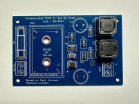
I made this board that can accomodate a Meanwell IRM-02 (2Watt) or IRM-03 (3Watt) with various output voltages.
Schematic and components are exactly the same as Mark’s AmyAlice board.
I don’t want to hijack Mark’s thread and I don’t think that this board deserve a dedicated thread, so if one want to make this board just DM me and I’ll send the Gerber files. I still have some boards available that can give away for mail cost only.
Or, under Mark permission, I can post here the Gerber files.
I’ve also used it in some very low power demanding device where I normally use some small encapsulated SMPS. In the beginning I just hooked up the SMPS to Mark’s board, but then I decided to make a dedicated board to avoid having flying wires and to add a fuse.
I made this board that can accomodate a Meanwell IRM-02 (2Watt) or IRM-03 (3Watt) with various output voltages.
Schematic and components are exactly the same as Mark’s AmyAlice board.
I don’t want to hijack Mark’s thread and I don’t think that this board deserve a dedicated thread, so if one want to make this board just DM me and I’ll send the Gerber files. I still have some boards available that can give away for mail cost only.
Or, under Mark permission, I can post here the Gerber files.
Attachments

Congratulations on your PCB design success, @mvaldes !! Please start a new discussion thread about your new board, and provide the Gerber files for downloads there. With its own thread dedicated to your board, diyAudio members will immediately know exactly who they should ask for technical support, debugging advice, component substitutions, and desired modifications. They should ask you, the thread starter and proud father of the board. Please feel welcome and free to either include or exclude "AmyAlice" from your thread title, whichever you prefer.
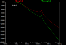
Here's a simulation of the effect of coupling between the inductors. The read trace estimates the coupling coefficient at 0.15, not exactly a transformer, but enough to impair the attenuation. The green trace assumes no coupling coefficient.
Attachments
@jackinnj thank a lot for your info.
When I made the board as post #142 I didn't read about your consideration regarding coupling between two adjacent inductors.
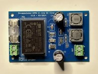
I've just made a new board today where I separate the inductors.
I'll follow Mark suggestion and soon will open a new thread for this board
When I made the board as post #142 I didn't read about your consideration regarding coupling between two adjacent inductors.
I've just made a new board today where I separate the inductors.
I'll follow Mark suggestion and soon will open a new thread for this board
Attachments

@jackinnj thank a lot for your info.
When I made the board as post #142 I didn't read about your consideration regarding coupling between two adjacent inductors.
I've just made a new board today where I separate the inductors.
I'll follow Mark suggestion and soon will open a new thread for this board
Beware of the trace width and cobber thickness - Marks Johnsons PCBs are rated for 3 A, that one looks a little light on the copper for that amperage (or specify the rated current of your board).
It might just be my eyes, if thats the case just ignore me

Oh yeah, did not think it throughSince these boards by @mvaldes are intended for IRM-02 (2W) and IRM-03 (3w), worst case scenario is 900mA for the IRM-03-3.3.


A question @Mark Johnson, I like the AmyAlice and it is compact. But could something as useful be done in a simialr vein by simpy using a single large inductor in line? Say 200 or 300 uF? Perhaps with one smaller bypass cap? I'm looking for simple and easy here. What does your experience in this area say? Thanks!
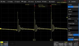
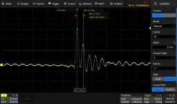
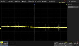
Here's some "before" and "after"Amy doing her thing on an HP Printer 32V 2.5A power supply. Note that the scale on the "after" is 2mV/div vs 20mV/div for the "before"
Attachments
Hello Forum Members,
I just received a small order of AmyAlice boards from JLCPCB. The ordering process was smooth with one possible glitch. When I received my stencil it was a large (I didn't measure, but maybe 12x14 inches) single sheet packaged between two pieces of hardboard. I was expecting it to be the same size as the pcb's. Whoops!
Did I do something wrong?
Thank you.
P.S. Thank you Mr. Johnson for designing these great projects!
Take another look at posts #1 and #18 of this thread @UncleMud , you'll see that the AmyAlice PCB is specifically designed to be soldered by hand. Component footprints are comically over-sized, giving you plenty of extra overhanging copper, to apply a standard wedge-tipped soldering pencil and standard wire solder. However, if you want to use solder paste and a stencil and a hotplate or reflow oven, you can sure do it that way too.
Unfortunately I'm not a stencil person so I can't advise how to use a 12 inch stencil on a 2 inch PCB, very sorry.
Pro Tip: by far the most common mishap when soldering SMD boards by hand, is OPEN CIRCUITS: Pin 3 is supposed to connect to signal trace "Alice" but, thanks to soldering mistake, they are not connected. By far the easiest and best way to diagnose and test for this common error, is to use the continuity test ("buzzer") feature of a multimeter. Probe right on the pins of a just-soldered component, and verify there is electrical continuity from Pin 3 to "Alice". If not: re-solder Pin 3.
- Home
- Amplifiers
- Power Supplies
- AmyAlice: DC filter for SMPS, using 2 feedthru capacitors + SMD assembly. max 3A & max 48V