PeeCeeBee V4H GB
- By shaan
- Group Buys
- 1813 Replies
Update (December 17 2022): The very last batch V4H Rev2 boards is going out! More details >Here.<
Update (August 2 2020):
PeeCeeBee V4H has been upgraded to Revision 2. This revision adds MOSFET short circuit protection, VAS buffer SOA protection and a couple minor changes. Full details >Here<. Updated schematic and layout snapshots have been shared below. Updated BOM and Setup Guide links have also been shared at the end of this post. Drill template remains unchanged.
Update (October 6 2021):
V4H Revision 2 PCBs available. Shipping resumed to most countries worldwide.
____________________________________
(Original text from here)
Hello everyone.
The PeeCeeBee V4H is finally here. As promised, PCBs will be available through group buys arranged in this thread.
Since the introduction of PeeCeeBee V4 early last year I have been receiving emails/PMs on a continuous basis with requests for a higher power version of the same amplifier. While most of the default components allowed for the use of a higher voltage PSU and more power would be readily available by paralleling the MOSFETs, it appeared to me that the amplifier's sonics can still be improved without using additional active devices in the signal chain or biasing the MOSFETs to 1A or 2A and turning the setup into a miniature furnace that would dramatically increase its requirements in every accompanying segment from Transformer rating to heatsink size. This is to say that much of V4's unused potential has been attempted to put to use. As a result, we now have PeeCeeBee V4H, the high power PeeCeeBee that won't need to be a furnace to deliver pleasant music. (However, the option for manual bias trimming remains available, very handy in the chilly winter nights IMO!)
A bit of detail: (it doesn't go too deep. 🙂)
The original PeeCeeBee V4 upto Rev1, uses emitter follower VAS and simple miller compensation at VAS stage that gives us a stable Class-AB "current feedback" amplifier with more than enough speed and much lower THD than any of its previous versions. Many members bought the PCBs, assembled them, listened to the amplifier and sent me more encouraging emails than I could imagine. While most of the comments I received on V4's sonics were positive, a few members who bought the PCBs in the group buys reported excellent sonics but only at 500mA or higher MOSFET bias.
V4's distortion at low frequency is very low and its LF performance with music input directly reflects that, with THD level being very low up-to around 2KHz with 100mA MOSFET bias. At gradually higher frequencies THD tended to gradually rise, as it normally would. However, while 500Hz to 5KHz THD measured low, level of higher-order harmonic content at 100mA bias wasn't as low as measured with 500mA/1A bias, resulting in a "thin" sound at low bias. It is a well known fact that higher order harmonics can be annoying at a lower magnitude than lower order harmonics. The output stage crossover distortion with its spiky and subtle nature was naturally the primary suspect and I was absolutely against building an amplifier with 1000V/uS slew rate (so to speak). Experiments followed.
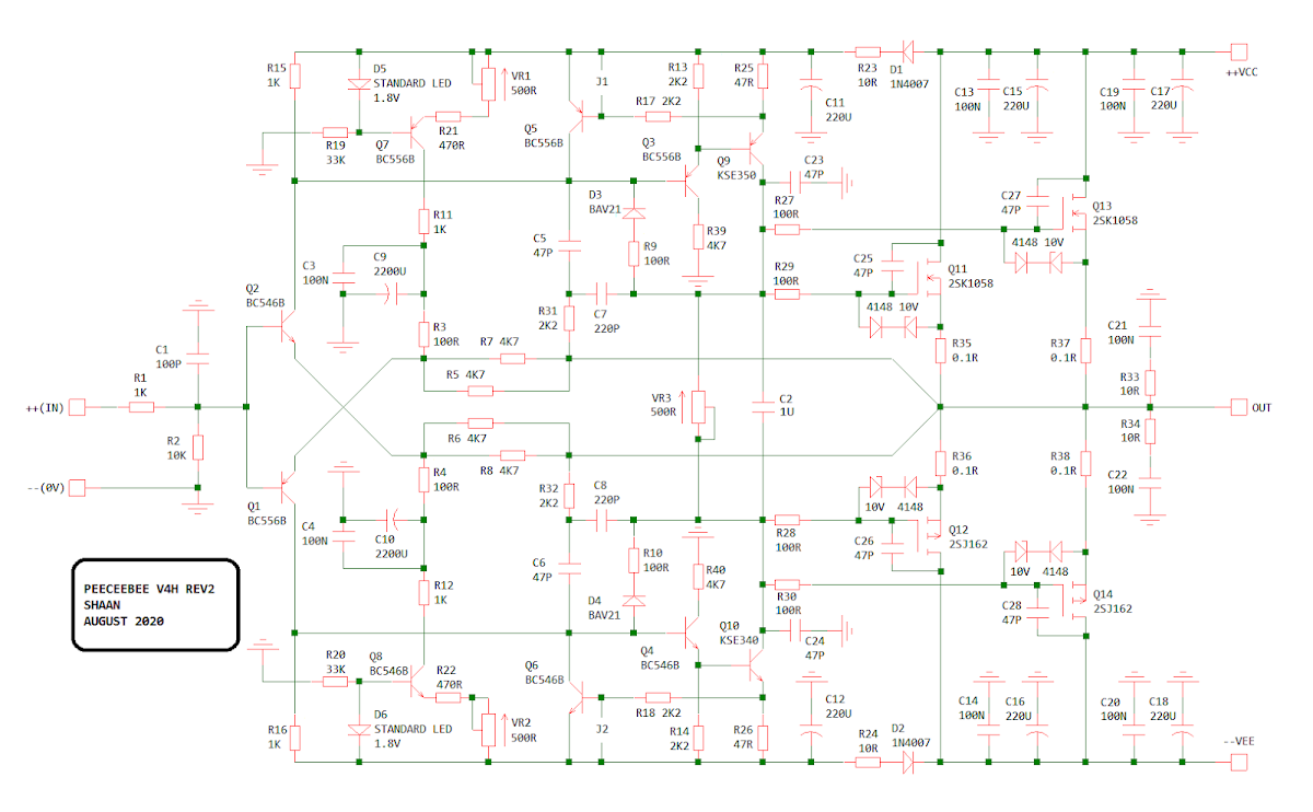
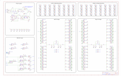
Meanwhile, I stumbled upon online and printed resources that illustrate "tricks" which, when properly applied, make use of the available negative feedback in a standard closed loop amplifier much more efficiently and effectively. After switching between a few of those "tricks" and measuring/listening to the setup for a few weeks I decided on one arrangement that is simple, has a visible improvement in the THD plot, most stable, sounded best, and noticeably better at HF than the vanilla V4 Rev1, at the same 100mA per MOSFET bias. It is a very simple modification of the miller compensation network that corrects HF distortion at output node and further attenuates higher order harmonics by forming a semi-local feedback network between the output and the VAS stage. The original simple miller compensation used just two capacitors. For this mod we need four additional passive components - two resistors and two more capacitors - R31, R32, C7, C8 as seen in the layout and schematic below. The idea is courtesy of the late Peter Baxandall, kindly made available for everyone by Douglas Self in his website. It is a very flexible technique and after much experimentation a combination of the involved components struck my setup, that had the best effect on sonics of this amplifier, and I went along.
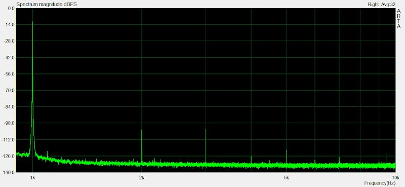
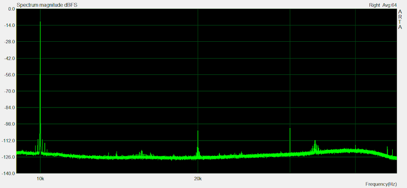
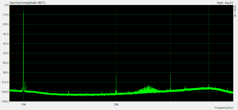
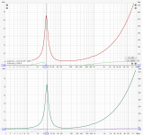
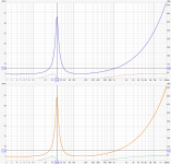
The technique is called "Output Inclusive Compensation", some call it "Transitional Miller Compensation". Whatever we call it, the mod is very simple and cheap, but its effect on sound is grand. The most elegant nature of this technique is that it helps the amplifier exactly where it is needed most. It has little effect on total distortion amount for frequencies below 5KHz but works on the crossover spikes and reduces higher order harmonic considerably, leaving THD to be consisting of almost entirely of second and third harmonic which are way less disturbing than say 5th and 7th and are already very low. At HF it works equally effectively reducing higher order harmonics even better and also having more effect on lowering second and third harmonics - for example check the increase in second+third harmonic levels in the 1KHz 10W and 1KHz 100W spectrum shots below. Compare that to the same in the 10KHz 10W and 10KHz 100W spectrum shots.
All in all, PeeCeeBee has yet again been improved in a key segment of its performance, harmonic distribution. The V4H is just as stable as the V4 and it provides not only more power headroom but has much less crossover distortion and sonics that are perceptibly more balanced throughout the octaves. The modification in compensation has also been incorporated in the lower power V4 Rev2 amplifier and it shows the same improvements in both measurement and sonics.
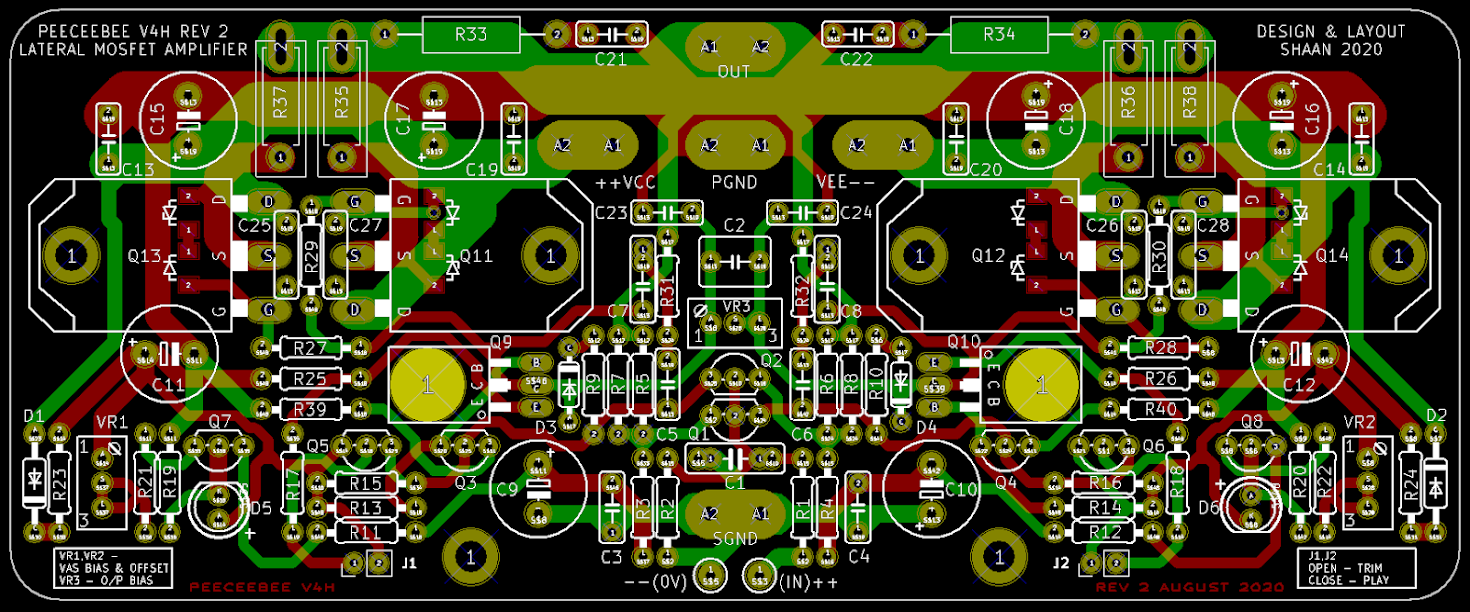
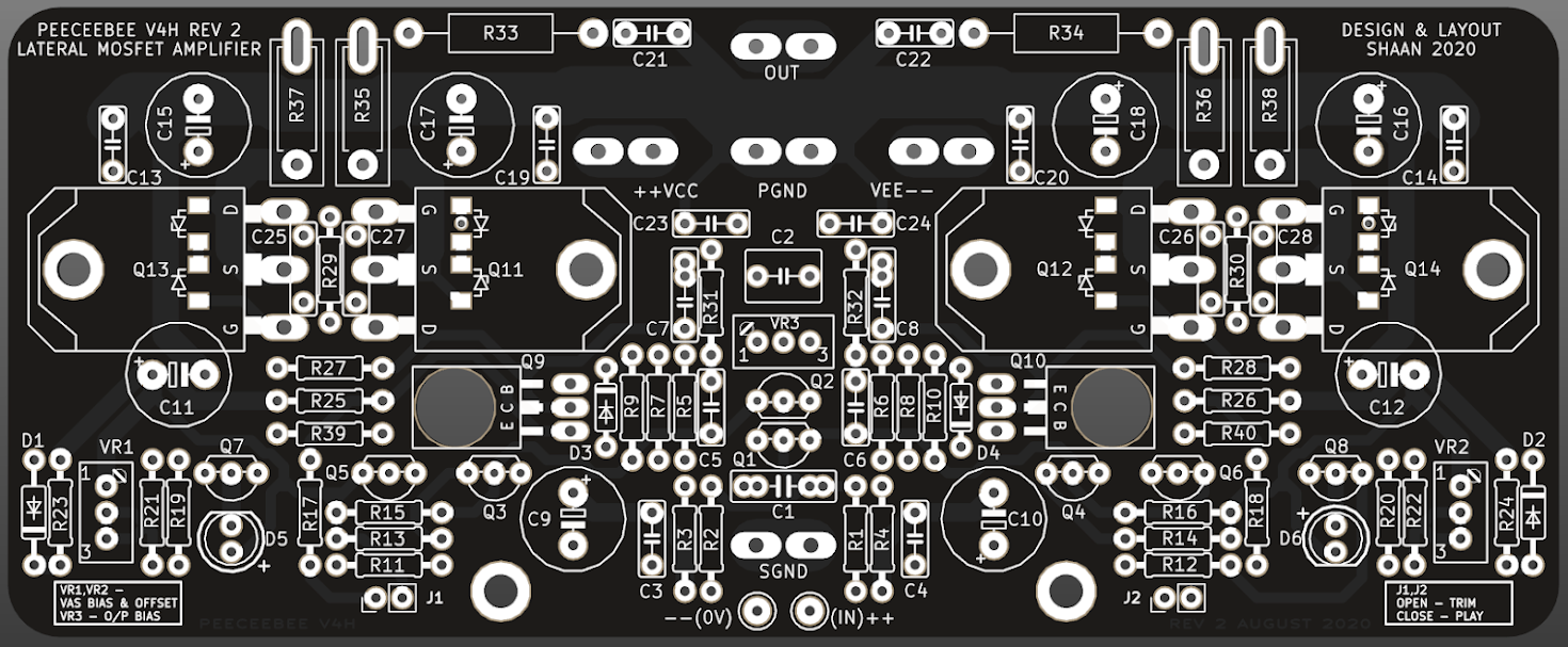
As shown, each of the feedback resistors have been divided into two 4K7 resistors to result into about the same total resistance in parallel but double the total dissipation limit. This will prevent these resistors from overheating during high power output. The 0.1R resistors allow for using unmatched MOSFETs. If your MOSFETs are matched, replace these resistors with wire links (use thick wire).
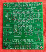
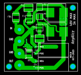
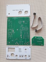
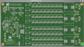
The PeeCeeBee V4H Revision 2 layout looks like this:
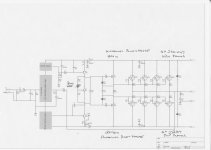
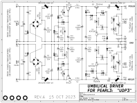
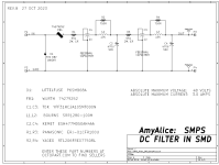
Revision 2 Schematic: (>full size<)
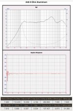
THD Plots: (1KHz - 0.001% source THD, 10KHz - 0.002% source THD, 100mA per MOSFET, 10mA VAS bias, no matching for any transistor pair except Q1 and Q2.)
1KHz 1W into 5R
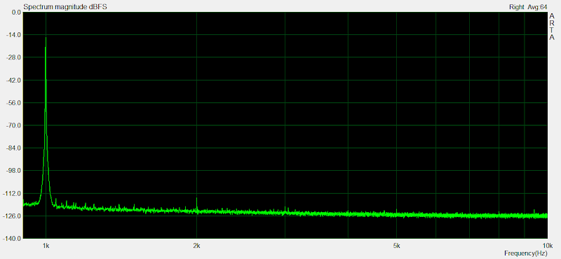
1KHz 10W into 5R
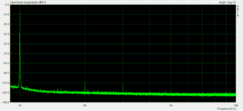
1KHz 100W into 5R
10KHz 1W into 5R

10KHz 10W into 5R
10KHz 100W into 5R
Specs:
Power - 150W/250W into 8R/4R load with +/-56V PSU (0.1% THD)
Frequency response(simulated) - ~2Hz to ~800KHz (-3dB)
Slew Rate - 100V/uS
Offset variation - +/-10mV
SNR - >110dB
AC gain - 24.5 (28dB)
DC gain - Unity
Input level for 250W into 4R - 1.5VRMS (~4V P-P)
THD:
100Hz 10W - 0.0005%, 100Hz 100W - 0.001%
1KHz 10W - 0.002%, 1KHz 100W - 0.003%
10KHz 10W - 0.002%, 10KHz 100W - 0.005%
Revision 2 BOM >Here<
Revision 2 Setup Guide >Here<
Drill Template >Here<
---------------------------------------------
Group Buy Information:
The layout is 150mm x 61mm Dual Layer.
Batch of 50, 75 or 100 PCBs will be printed depending on interest. The boards will be 2.4mm thick with FR4 material, 60micron copper, HASL finish, white silkscreen and black solder mask.
2. Registered Post (cheaper, 30-40 days delivery time. Available for all countries)
---------------------------------------------
Thanks.
shaan
Update (August 2 2020):
PeeCeeBee V4H has been upgraded to Revision 2. This revision adds MOSFET short circuit protection, VAS buffer SOA protection and a couple minor changes. Full details >Here<. Updated schematic and layout snapshots have been shared below. Updated BOM and Setup Guide links have also been shared at the end of this post. Drill template remains unchanged.
Update (October 6 2021):
V4H Revision 2 PCBs available. Shipping resumed to most countries worldwide.
____________________________________
(Original text from here)
Hello everyone.
The PeeCeeBee V4H is finally here. As promised, PCBs will be available through group buys arranged in this thread.
Since the introduction of PeeCeeBee V4 early last year I have been receiving emails/PMs on a continuous basis with requests for a higher power version of the same amplifier. While most of the default components allowed for the use of a higher voltage PSU and more power would be readily available by paralleling the MOSFETs, it appeared to me that the amplifier's sonics can still be improved without using additional active devices in the signal chain or biasing the MOSFETs to 1A or 2A and turning the setup into a miniature furnace that would dramatically increase its requirements in every accompanying segment from Transformer rating to heatsink size. This is to say that much of V4's unused potential has been attempted to put to use. As a result, we now have PeeCeeBee V4H, the high power PeeCeeBee that won't need to be a furnace to deliver pleasant music. (However, the option for manual bias trimming remains available, very handy in the chilly winter nights IMO!)
A bit of detail: (it doesn't go too deep. 🙂)
The original PeeCeeBee V4 upto Rev1, uses emitter follower VAS and simple miller compensation at VAS stage that gives us a stable Class-AB "current feedback" amplifier with more than enough speed and much lower THD than any of its previous versions. Many members bought the PCBs, assembled them, listened to the amplifier and sent me more encouraging emails than I could imagine. While most of the comments I received on V4's sonics were positive, a few members who bought the PCBs in the group buys reported excellent sonics but only at 500mA or higher MOSFET bias.
V4's distortion at low frequency is very low and its LF performance with music input directly reflects that, with THD level being very low up-to around 2KHz with 100mA MOSFET bias. At gradually higher frequencies THD tended to gradually rise, as it normally would. However, while 500Hz to 5KHz THD measured low, level of higher-order harmonic content at 100mA bias wasn't as low as measured with 500mA/1A bias, resulting in a "thin" sound at low bias. It is a well known fact that higher order harmonics can be annoying at a lower magnitude than lower order harmonics. The output stage crossover distortion with its spiky and subtle nature was naturally the primary suspect and I was absolutely against building an amplifier with 1000V/uS slew rate (so to speak). Experiments followed.
Meanwhile, I stumbled upon online and printed resources that illustrate "tricks" which, when properly applied, make use of the available negative feedback in a standard closed loop amplifier much more efficiently and effectively. After switching between a few of those "tricks" and measuring/listening to the setup for a few weeks I decided on one arrangement that is simple, has a visible improvement in the THD plot, most stable, sounded best, and noticeably better at HF than the vanilla V4 Rev1, at the same 100mA per MOSFET bias. It is a very simple modification of the miller compensation network that corrects HF distortion at output node and further attenuates higher order harmonics by forming a semi-local feedback network between the output and the VAS stage. The original simple miller compensation used just two capacitors. For this mod we need four additional passive components - two resistors and two more capacitors - R31, R32, C7, C8 as seen in the layout and schematic below. The idea is courtesy of the late Peter Baxandall, kindly made available for everyone by Douglas Self in his website. It is a very flexible technique and after much experimentation a combination of the involved components struck my setup, that had the best effect on sonics of this amplifier, and I went along.
The technique is called "Output Inclusive Compensation", some call it "Transitional Miller Compensation". Whatever we call it, the mod is very simple and cheap, but its effect on sound is grand. The most elegant nature of this technique is that it helps the amplifier exactly where it is needed most. It has little effect on total distortion amount for frequencies below 5KHz but works on the crossover spikes and reduces higher order harmonic considerably, leaving THD to be consisting of almost entirely of second and third harmonic which are way less disturbing than say 5th and 7th and are already very low. At HF it works equally effectively reducing higher order harmonics even better and also having more effect on lowering second and third harmonics - for example check the increase in second+third harmonic levels in the 1KHz 10W and 1KHz 100W spectrum shots below. Compare that to the same in the 10KHz 10W and 10KHz 100W spectrum shots.
All in all, PeeCeeBee has yet again been improved in a key segment of its performance, harmonic distribution. The V4H is just as stable as the V4 and it provides not only more power headroom but has much less crossover distortion and sonics that are perceptibly more balanced throughout the octaves. The modification in compensation has also been incorporated in the lower power V4 Rev2 amplifier and it shows the same improvements in both measurement and sonics.
As shown, each of the feedback resistors have been divided into two 4K7 resistors to result into about the same total resistance in parallel but double the total dissipation limit. This will prevent these resistors from overheating during high power output. The 0.1R resistors allow for using unmatched MOSFETs. If your MOSFETs are matched, replace these resistors with wire links (use thick wire).
The PeeCeeBee V4H Revision 2 layout looks like this:
Revision 2 Schematic: (>full size<)
THD Plots: (1KHz - 0.001% source THD, 10KHz - 0.002% source THD, 100mA per MOSFET, 10mA VAS bias, no matching for any transistor pair except Q1 and Q2.)
1KHz 1W into 5R
1KHz 10W into 5R
1KHz 100W into 5R
10KHz 1W into 5R
10KHz 10W into 5R
10KHz 100W into 5R
Specs:
Power - 150W/250W into 8R/4R load with +/-56V PSU (0.1% THD)
Frequency response(simulated) - ~2Hz to ~800KHz (-3dB)
Slew Rate - 100V/uS
Offset variation - +/-10mV
SNR - >110dB
AC gain - 24.5 (28dB)
DC gain - Unity
Input level for 250W into 4R - 1.5VRMS (~4V P-P)
THD:
100Hz 10W - 0.0005%, 100Hz 100W - 0.001%
1KHz 10W - 0.002%, 1KHz 100W - 0.003%
10KHz 10W - 0.002%, 10KHz 100W - 0.005%
Revision 2 BOM >Here<
Revision 2 Setup Guide >Here<
Drill Template >Here<
---------------------------------------------
Group Buy Information:
The layout is 150mm x 61mm Dual Layer.
Batch of 50, 75 or 100 PCBs will be printed depending on interest. The boards will be 2.4mm thick with FR4 material, 60micron copper, HASL finish, white silkscreen and black solder mask.
1. International Air Parcel (recommended, 15-20 days delivery time, but a bit expensive. Covers most countries).PCB price is US$20 for one unit.
Two forms of shipping are available.
2. Registered Post (cheaper, 30-40 days delivery time. Available for all countries)
After GB list is full, first invoice for PCB price will be sent to each GB member's email address. After payment GB order will be confirmed for the member and PCB batch will be ordered to fab shortly afterwards. After I receive the PCB batch, second invoice for preferred mode of shipment (International Air Parcel or Registered Post) will be sent to each member.
International payments are accepted through PayPal only and payments from within India are accepted through bank account transfer/deposit, NEFT, IMPS etc.
Delay between placing the batch order to PCB plant and delivery of the boards to me will be 18-20 days.
---------------------------------------------
Thanks.
shaan


 Copyrighted materials removed by moderation.