Let me start to say that this is only simulation with SPICE.
But I have no doubt this amplifier should do very well for real.
I challenge you to do something like it or even better 🙂
Design goals:
1. Fully discrete
2. Max 3 transistors
3. Voltage gain 4-5
4. Load 1Vrms into 4.7kOhm
5. Regulated 12V supply
Result in SPICE:
1. Voltage gain 4.6
2. THD 0.00011%
3. Frequency response 5Hz-300kHz -3dB
Last edited:

Who today needs extra gain besides the existing gain of the integrated/power amplifier? This is a serious question based on the countless threads here of people who build preamps and then have hum/noise/GAIN issues.
With regards to the challenge: a wire is better and it saves 2 caps in the signal path too.
With regards to the challenge: a wire is better and it saves 2 caps in the signal path too.
Last edited:
The simplicity and available parts makes it very appealing!
Although my preference is a gain of 2-3
I configure and build some various integrated amps
I might try it on breadboard - my latest parts order is going in soon
I would play around, scope output and subjective listen only
PCB, I cant do
Although my preference is a gain of 2-3
I configure and build some various integrated amps
I might try it on breadboard - my latest parts order is going in soon
I would play around, scope output and subjective listen only
PCB, I cant do
Europeans with our 500mv rms headphone out limit. Or people with lower level source devices, i should build a nice source device like a dac/cd player combo.Who today needs extra gain besides the existing gain of the integrated/power amplifier? This is a serious question based on the countless threads here of people who build preamps and then have hum/noise/GAIN issues.
With regards to the challenge: a wire is better and it saves 2 caps in the signal path too.
Headphones are a too heavy load I think and the 10 µF output cap says that too. 1V rms on headphones means you will have to find a new hobby soon 🙂
The last 40 years sources produce 2Vrms max. and this preamp has an allowable output voltage of 1Vrms so what is there to amplify with a gain of 4.6? The average source has lower Zout so it can drive the following device better then the preamp can.
In other words: to be able to compete with the sources connected to it or have at least comparable performance it should be able to drive lower Zout at higher than 2V rms output voltage or with a gain of 1x as a buffer.
However for classic 40+ years old analog devices and classic phono stages that sometimes have not even a few hundred mV output voltage it can be of use as it is. As interstage amplifier in the same casing as the phono preamplifier so it is partly updated to current standards.
Last edited:
Who needs it? lineup needs, who develops it for their own entertainment. 🙂Who today needs extra gain besides the existing gain of the integrated/power amplifier? This is a serious question based on the countless threads here of people who build preamps and then have hum/noise/GAIN issues.
With regards to the challenge: a wire is better and it saves 2 caps in the signal path too.
Last edited:
If one replace the single ended buffer U2/U3 by a push pull power darlington buffer, we came to the good known "el cheapo" topology - go to fig. 1 underLet me start to say that this is only simulation with SPICE.
But I have no doubt this amplifier should do very well for real.
I challenge you to do something like it or even better 🙂
Design goals:
1. Fully discrete
2. Max 3 transistors
3. Voltage gain 4-5
4. Load 1Vrms into 4.7kOhm
5. Regulated 12V supply
Result in SPICE:
1. Voltage gain 4.6
2. THD 0.00008%
3. Frequency response 5Hz-300kHz -3dB
View attachment 1449738
https://sound-au.com/project12a.htm
Yes thats why you can buy a fancy dongle for 30$ and even get balanced out (sometimes)Headphones are a too heavy load I think and the 10 µF output cap says that too. 1V rms on headphones means you will have to find a new hobby soon 🙂
The last 40 years sources produce 2Vrms max. and this preamp has an allowable output voltage of 1Vrms so what is there to amplify with a gain of 4.6? The average source has lower Zout so it can drive the following device better then the preamp can.
In other words: to be able to compete with the sources connected to it or have at least comparable performance it should be able to drive lower Zout at higher than 2V rms output voltage or with a gain of 1x as a buffer.
However for classic 40+ years old analog devices and classic phono stages that sometimes have not even a few hundred mV output voltage it can be of use as it is. As interstage amplifier in the same casing as the phono preamplifier so it is partly updated to current standards.
Hi, colleague!2. THD 0.00008%
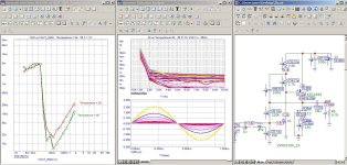
I'm interested in such simple solutions, so I took the liberty of running a simulation in MC12.
Overall, the frequency response matches well, and the distortion is low.
However, at low signal levels, there's a slight anomaly or nonlinearity.
The distortion level is about 0.005%.
P.S. Perhaps you need to play with the capacitor values.
Attachments
Last edited:
Who today needs extra gain besides the existing gain of the integrated/power amplifier? This is a serious question based on the countless threads here of people who build preamps and then have hum/noise/GAIN issues.
With regards to the challenge: a wire is better and it saves 2 caps in the signal path too.
Perhaps paradoxically, but i have always preferred having a separate line stage, even if the source has a reasonably good volume control and driving ability. Most sources, however, do not have these. And how do you deal with a phono preamp?
Post #5.Perhaps paradoxically, but i have always preferred having a separate line stage, even if the source has a reasonably good volume control and driving ability. Most sources, however, do not have these. And how do you deal with a phono preamp?
El Cheapo is CFB, this one is VFB...If one replace the single ended buffer U2/U3 by a push pull power darlington buffer, we came to the good known "el cheapo" topology - go to fig. 1 under
I assumed R3-C3 a bootstrap config, but it was not so, but intended as an overall gain setting.
The gain then is (C3 acts as a bootstrap with R1-R8 for U1) R3 / ( R2 // (R4 + Rsource) ), which is source depending.
That R1-R8-C3 bootstrap trick for U1 limits the output swing somewhat.
The dynamic headroom is not so much with a supply of 12Vdc.
The gain then is (C3 acts as a bootstrap with R1-R8 for U1) R3 / ( R2 // (R4 + Rsource) ), which is source depending.
That R1-R8-C3 bootstrap trick for U1 limits the output swing somewhat.
The dynamic headroom is not so much with a supply of 12Vdc.
There is also this current feedback version, CFB.
Also 3 transistors.
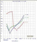
THD compare:
0.00008% My best
0.00054% CFB
0.00182% Opamp

Also 3 transistors.
THD compare:
0.00008% My best
0.00054% CFB
0.00182% Opamp
Ok, now with CFB you have little bit more THD (simulated) that is below any hearing threshold anyway. But you also removed noisy 47k FB resistor from input, and check HF response now comparing to first iteration, I bet it will go to MHz
I like last CFB iteration very much. @lineup , if you are in mood to complicate a bit; copy and mirror paste complete circuit , delete both C1 and one R5, than just connect remaining R5 to emitter of other side U3 (instead of GND). Should result in fully differential fast amp with even harmonic distortion canceled.
- Home
- Source & Line
- Analog Line Level
- My best discrete preamp with 3 transistors