Help with an Audionics CC-2. Good with a soldering iron?

I have an old favorite amp I use for a pair of slightly modified Canton Plus C sub/satt setup in my bedroom.
It is an original Audionics CC-2.
The caps are more than dried up now and causing me to unplug before total failure.

I have a neurological disorder that causes my hands to shake when trying to do precision work. (Cannot even use my turntable anymore)

I am in Southern VA US.

Any of you within a reasonable drive of DC/Roanoke/Raliegh-Durham who is good with a soldering iron interested in the project?
The cap replacement is very straight forward, but I do not want to end up with shaky globs/damage trying it myself.

DIY ribbon mic

Hey guys, I just finished a diy ribbon mic and it sounds sweet!!! Compered it to some other brands and I really like its character.
The only downside is I need to cranck up about 8-10db more then the other ribbons I compared with.
I am using a self wired transformer (I will provide with firther info about the core and wiring), 52N magnets and for now I am experiencing with 1.8-2.5u AL foil . I get an avarage number of 11-13 corrugations(maybe to little?) on a 5cm long, 0.5cm wide ribbon .
I guess I just need a clue on what should I be looking next to try and increase the output gain.
Will apreciate any help 🙂😎

Aleph J - First Test Issues / No Sound / Blinking LEDs

I stuffed the Aleph J boards today and did a quick mount in the chassis for a test.

Adjusting the bias for 350mv, then 400mv is no problem on either board.

When I connect a speaker, sometimes LED3 will dim and LED2 will go bright. Then consistently maintain this state if I turn the output of my source up.

If I turn the source output up to the extreme, I'll hear some muffled, highly distorted sound. I may not have heard it at all but my speakers are very efficient. At the same time, LED will blink - seemingly with the amplitude of the input signal.

The behavior is exactly the same on both boards - so whatever mistake I made, it's consistent 🙂

I don't know where to start troubleshooting, and would greatly appreciate help.

The only test tools I have are some inexpensive digital multi-meters.

Thanks in advance!

Anyone Driving An F4 With A 300B SET?

When I became aware of the F4's ability to be driven by a main amplifier's output, I started wondering if I could use it to drive a wider range of speakers with my SET - and still have the SET character?

I'm not sure how significant this is, but the 300B is a Tubelab SE.

Aside from 300B's any descriptions about the F4 being driven by low power SET amplifiers would be great! Please include your speaker. Thanks!
  • Like
Reactions: oltos

Heat-sink to be clamped to the magnet of the speaker

Hello everybody,

I've jsut got a webinar invitation for some 3M filters:

http://www.filter-equipment.com/uploads/1/2/2/8/122858212/3m-high-flow-hfr-series-data-sheet_1.pdf
Look at bottom right of page 2. That one has the purpose to increase the filtering surface area of a flow passing through the filter, but...
Imagine that the flows doesn't pass through the membranes but tangentially... imagine that is not a membrane but a sheet of Alluminium, imagine it is air and not water and imagine it clamped on the magnet of the cone.

Has anyone ever done a "clampable heat sink" made in the 3M HFR way, to be clamped on the magnet and with the same diameter of the speaker?

The purpose is:
- increase the heat tranfer coefficient (when the cone moves, the convection goes from natural to forced (by the cone moving), so increase the capability to transfer heat;
- increase in the surface area of the magnet, so increase the capability to transfer heat.

This will give two scenarios:
- lower temperatures for the magnet, so higher reliability for the speaker;
- higher allowed power handling.

Has anyone an idea on how (badly) it would impact the sonic performance of the speaker?

By doing the "radiator" in Alluminium and thin, it will give optimal passage for the air, low weight, low costs and less sonic impact, but how can it be calculated?

Thank you all in advance
Roberto

FaitalPRO 4" 4FE35 as Dolby Atmos ceiling speakers?

Looking to add four ceiling speakers to my 5.1 to make 5.1.4 for Atmos.
I want to do this on a budget though, since I'm a couple years away from a total home theater build.
It seems the Atmos ceiling speakers don't need to work below 150hz and should be somewhat non-directional.
At $100 for four speakers, any reason not to try the 4FE35's?

I don't have Atmos experience yet, but based on what I've read, I don't understand why some people are going with large speakers for the ceiling.

FaitalPRO 4FE35 4" Professional Full-Range Woofer 8 Ohm

CROWN 5000VZ

Hello good people!

Thank you for any time you're able to put towards this in advance.

I have a Crown 5000VZ with an unusual problem. It doesn't pass sound, here's the LED situation
ODEP - off - both channels
SIGNAL / IOC - ON, GREEN - both channels
Load / Limit - ON, RED - both channels
DC/LF - ON - both channels

The service manual doesn't cover this combination, but the closest one listed suggests that 'the output stage has been damaged in both channels' and that is it.

Things I have done
Checked the flyback diodes for shorts - D596, 507, 508, 509
Checked the driver and pre-driver transistors for shorts and opens
Checked semi conductors 8188-2 and 8187-4 on all output boards
Repaired numerous dead traces on the output boards (corroded by some obscure green compound)

Would really appreciate any help you good people can offer!

Thanks

Problem in reclocking the Raspberry Pi

Hello everyone!

I develop the reclocker for Raspberry Pi.
I did I2S dividers for BCLK and LRCK.
For testing I use the Raspberry Pi 4 and Volumio OS with selected HiFiBerry DIGI as I2S output.
I connect the Raspi I2S output to my DAC board AK4490, in finally I got corrupted audio.
All wires for I2S connection is very short (not length as 10 cm).
My questions is:
- Which I2S DAC I need select in the Volumio for get native I2S?
- Maybe needed make a configure the I2S driver via I2C or SPI interfaces?

Adding Vintage VU Meters to an Aleph J

I recently picked up a pair of vintage Weston VU Meters from a Quad Eight.

s-l1600.jpg


I am hoping I can add them to an Aleph J that I am building. (I previously built and F5 without issue.)

Has anyone implemented vintage meters of this type? I'm wondering if I can use this PCB board to do it.

s-l1600.jpg


I can run 15v from a small transformer or add a regulator and use the 24V from my existing power supply.

One thing I'm unclear on is where this could go in the chain from preamp to amp to speaker outputs. In other words, what is the input to the VU board?

Will it have any negative input on the sound quality?

This is purely for looks.

Building a UCD400OEM amp and has problems with some modules.

Hi.
I'm building a 4ch ucd400oem amp (driven by two smps400a400) + 4 channels of ucd250lp (one smps400a180).

I made input buffers pcb and all, that part seems to work good (exept one of the ucd400 input buffers that makes the connected module ticking (sound from the speakers) about once a second, no other sound than that), its like some protection is kicking in, cant get whats wrong with it, maybe I'll have to rebuild a new one from scratch.

And I have a problem with one of my ucd400oem modules. it is dead silent, no sound what so ever. I bought 4 of them on ebay and the other ones works as expected. If i connect one working ucd400 oem to the input buffer then it works, switching place with the ucd400oem that not works and there is no sound at all. So there have to be som wrong with the module.


I also have one smps400a400 that has negative rail shorted to gnd. measured when not connected.
I have just sent a question to hypex regarding the smps but I know it will take a while before I get an answer so I thought I could ask hare also. What could be wrong with this one? I have tried to see if there are some metal pieces on the pcb shorting the - and gnd but could not find anything.

This really off putting because I really wanted this to work, already spent a lot on this both time and money. Any help would be appreciated!

some pictures of my input buffers.

IMG_20180809_154006.jpg
IMG_20180809_154018.jpg
Thanks /Joel

Add a trigger input on ncore ncXXXmp modules

Hi,

Just received and built my nc122mp amplifier, in a ghent audio case.
For now, the amp is always on, but I would like to use a trigger input.
I'm not an electonic guru, so I'd like your approbation before doing anything ^^

I undestand that I have to deal with the ncore module H-bus connector.
Need to cut the J6.3 (PS standby output) to J6.9 (PS Enable) bridge, and add kind of relay that will be open/close according to the mono 3.5mm jack input?

My preamp doesn't have trigger output, so I'll use a wifi/IR outlet with a 5V power supply plugged in on it to trigger the amp.

Any recommandations ?
Thanks

Cheap Active/Passive Full-Range Speaker

I am looking for a cheap simple system for the kids to play around with.

A quick search gives party speaker systems at different prices but you have systems as The box PA 15 DSP as well. A Bluetooth speaker is easy to use but membrane area adds some significant punch in the sound.

Are there better alternatives than the PA system above in that price range?

I think a diy project will be more expensive even if the sound could be better with proper designed speaker cabinets. Only the speaker element will most probably be more expensive than these cheap active systems.

Cyrus One V6 - Phono Pre Amp Gain

Hey guys,

Hope you’re all staying safe and well.

I’m using a Cyrus One V6 solely as a phono stage in my setup. Naturally it is quieter than let’s say a CD input but it still seems a little on the quiet even as a phono stage. I love the quality of the sound and I’m wondering if any of you guys know of any “mods” to squeeze a little more gain?

Thanks guys

Why do SMPS sound rolled off in the high frequencies?

I have used a number of SMPS to power my music server over the years, but none of them has got close to my Paul Hynes SR7 in the high frequencies.

Some computer power supplies, such as high end corsair, and the AX1600i I had have very good voltage regulation and ripple suppression - the AX1600i sounded to me as identical in the lower and mid range, but rolled off / unsatisfactory upper band.

I use Hypex SMPS in my amplifiers and these are completely perfect accross the frequency spectum to my ears.

Has anyone else experience this, and any thoughts reasoning why these computer smps sound rolled off in the high notes, yet the Hypex power supply doesn't seem to do this.

Thanks

EX CDMA/GSM MOSFET

Hi,

I found in flea market very large number MOSFET from ex CDMA/GSM BTS or a brand new one from datasheet I know the have 60 to 300w in 1800-2200MHz because the price is very cheap. from 1USD to 10USD I been thinking to use it in Pass design amplifier. but before I regret my idea if some one kind enough to give me idea or suggestion about which scheme and parameter I must use Vmax, I max etc
some of parts I already have is,
MRF6S18060NR1
mrf8s9260hs
MRF8P9300HS

All idea is appreciated.
Anton

Mastering Engineer vs Loudspeaker Engineer = Mastering Monitors.

YouTube

My perspective is based on my feelings, after seeing this video. Loudspeaker design and Mastering go hand in hand. If we take Earl G and lock him in a room with Bob Katz, for a year, though they represent decades of research, both would potentially "master" each others material quickly, because its so closely related.
Mastering has made me a better loudspeaker designer and loudspeaker design has made me a better mastering engineer.

I hope this turns into a discussion about what needs to be done to advance both sides of the fence and how, in 2020. Also mentions of Standout products or Practices.


I named the post as I did because that is the formula, in my mind to move forward....The audience (general public) is less important than is being treated in this video, The audience is "uneducated and incorrect" and we are educated and way more correct. Floyd said it, and I am witnessing, the consumer products move closer to mastering monitors and not visa versa which to me is a slow showing trend of the audiences (general public) audio intelligence increasing causing their expectations to become more like the Mastering engineer. FLoyd shows how they did their double blind test and I see a larger portion of casual listeners than critical listeners ...that can only makes sense because one group has a much bigger pocket book.
I thought.....I thought.....I thought we were moving away from the smiley face voicings and "max bass boost" type systems. The General public will lead you to more non sense if left unchecked....just kick them out of the picture so early in the game. Loudspeaker design, mainly, should be left up to Mastering engineers and Loudspeaker engineers until the later stages, like we have 10 models that we screened out, we'll use the general public to figure out what they like out of what we find acceptable.
So why, why do I say this? Mastering Engineers are the Ultimate Critical Listener! We have the ears! Our job consist of creating the most neutral playback, listening, and adjusting, to create an emotional, dynamic, tonally balanced presentation from scratch. This process is almost identical to the objectives of loudspeaker design but a mastering engineer repeats this process, from scratch, many many times over in a week. How many loudspeakers can a designer create from scratch and go through the hoops to completion in a week? So at the end of the day, Mastering engineers have the experience advantage. If a speaker is perceived well, is a question that should only be answered by mastering engineers since we have the ears. Loudspeaker designers seem to need a group of people, to make decisions. Making these types of decisions are what Mastering engineers do on a daily basis, by their lonesome , and whether they are right or not, is feedback that can be discovered within a short time frame. So not only do we constantly listen and manipulate the signal, several times over, more times in a week, than the loudspeaker designer can be challenged...we are also obsessive with being right, so we are constantly checking our work, within the week, to see if we are "right"......if we are right about our choices voices versus what we hear....we have successful mixes that translate from system to system and successful careers in the field....if the loudspeaker designer is "wrong"....only the mastering engineers and other niches of high critical listening care!!!! How is this possible!? A good production sounds fine on un-perfect speakers! Creating these types of mixes that sound good on every additional system post the studio...cannot be done on consumer level speakers...so not only do Mastering Engineers have the ear training, they have it based on systems that are an attempt at perfection, designed by loudspeaker engineers.

So the advancement of the field of Perfect Speakers should only be pushed forward by the people who are the main consumer of perfect loudspeakers who conveniently happened to be the same people who design the signal in the first place, and thus need perfect speakers regardless of preference, Mastering Engineers....

Go

Almost-Newbie needs some 3-way speaker & tri-amping advice :)

Hi all,

I'm an IT guy, 37, my father is the big guru (built couple of tube & solid state amps) but we're not living together and he almost doesn't have any more time to teach me on basics of electronics or hi-fi or whatsoever.

- Ca. 15-20 years ago my first speaker set was 2 fullrange boxes made of MDF, I cut the holes, drivers in, glued together - perfect. Then blown with Prodigy at that time 😀 - well, youth .. you know ..

- Ca. 15-10 years ago my 2nd project: 4 boxes, 2 left, 2 right, all mdf. (3 way, separate boxes for Bass and mid+highs). 2x12" (30cm) bass drivers / side, 4 Ohms each, in series, with front-facing bass reflex holes. Mid+high in a separate box on top of it.

- Passive filter for the 3-way was set-up by myself, based on my father's instructions. He calculated me the 2 basic X-over freqs matching my speakers and I had to solder them together and wound the coils also by myself from his copper wire, using a ferrite core (for the bass coils only).. 3-way classic Butterworth design.

Still using these huge boxes, but the speakers need to be changed. Mids are from Visaton, silk dome ferrofluid tweeters from Audio-Ton ( = almost noname, sound excellent however..) .. bass drivers you can forget .. cheap whatever types..


Now I want to sweep the table and start all-new again with a far better project.

What I have:
- precision soldering iron 😀
- contact to a local company building high-end grade extraordinary speakers, also for hobbyists, partly or fully .. I'd have them build my boxes. BIZSÓK Loudspeaker Manufactory
- my ultimate-looking wanna-own speaker design http://www.canhifi.com/Resources/ProductImage/ImageFile/beethoven_concert_grand_1_xtralarge_xtralarge_XtraLarge.jpg
- a 3-way active crossover design I'm going to use from Linkwitz Lab - Loudspeaker Design, fine tuned to my needs with help of my father..

Where I need advice on:
1. High sensitivity, detailing, fast, audiophile-grade speaker driver recommendation (exact models maybe?) - or at least a good store ! For bass, mids and highs.
2. No big magic pls, I'm rather the realistic type of person, not believing in placing spikes below the 230V/AC splitter 😀
3. Some questions regarding tri-amping with different DIY amps

Target music: sadly I'm almost an all-eater but don't want to have 2 separate systems..
- electronic music (Goldfrapp, Air, Morcheeba, Asteroids Galaxy Tour, Jean Michel Jarre)
- Classics (Karajan Gold collection on LP, mint condition)
- Rebecca Pidgeon, Loreena McKennitt, Dire Straits, Mark Knopfler, Diana Krall CDs, SACDs, LPs and high-res DSDs
- Deep house, techno, electronic music (all lossless)


For topic #1 my imagination so far:
- 8 Ohm total. 2-4 bass drivers, 1 or 2 midrange(s), 1 tweeter
- tweeter would be a ribbon type, I LOVE their sound. DIY amp design would be carefully selected to be able to drive such tweeters with transformers.
- mids: no idea. Something from Visaton, Seas, Fostex, Scan Speak, others.. ?
- bass: no idea. Maybe 8-10" ones ? For more power handling I plan 2 pcs here (at least) - does it make sense to have 4 pcs ? (Does it increase overall sensitivity and detailing capability of the bass section while retaining decent power handling ? I hate slow bass..)
- all 3 ways at around 90+ dB sensitivity, I would like to hear details
- 80% stereo music, 20% home cinema use (2.0 stereo, maybe 2.1 but no sub planned yet)

Topic #3 - tri-amping, DIY amps.
- Does it make sense (or is it a completely wrong idea) of using a mixed setup ? MOSFET amps for bass, tube class AB pushpull for mids (Tung-Sol KT150-s), tube OTL for tweeters ? Considering phase coherence mostly.
- Gains matched, in the amp design and also on the active crossover network (matching the parameters of the driver sections of course)
- Where to put the volume controls ? (Stepped attenuators). The more towards last amp stage or right at the beginning at line level in the preamp ? (Before splitting into 3 ways).
- Passive preamp OK ? (with XLR Input from high-res DAC)

Any advice or useful info warm welcome. Please forgive me for my English and try not to laugh if I seem to dream big with so few knowledge about electronics. 🙂 It's always that I dream and my father helps me to put things ready onto the table. 😉 I'll need him for this project too but without your valuable help it would still remain just a simple oldschool design without any traces of quality. I really strive for quality here (combined with decent power), at least as far as a hobbyist I can go..

Many-many thanks !!

Networked volume control

Hi All,

I hope all is well out there.

I love my Schiit Saga (R2R), I basically want a networked version of it (I use Roon for my music almost exclusively now), something like the ESP32 controlling an R2R or a LDR based volume.

I would want the firmware to support an interface that allows setting and querying the volume level. Home Assistant automation software has ESPHome which allows you to connect ESP's with automation easily.

I have seen RelaiXedPassive, LDR Pre MkII and some other bits out on the internet but nothing seems to be quite what I need, is anyone else doing this?

I'm happy soldering surface-mount, ordering parts from DigiKey and I have used Gerbers to order boards from PCBWay, so the DIY route is all good, I've never designed a board though.

Thanks for looking.

Cheers
Richard

System: Roon (PC) >> Pro-Ject Pre Box S2 (DAC) >> Schiit Saga (R2R Volume) >> Valvet A1r's (Amp) >> Salk SongTower QWT (Speakers)

External volum control, pc multichanel

helo good folks, I'll get right to it. I don't know much about Audio and such but I was wondering if there is a mixer or something that exists that allows me to change the volume levels of individual programs of my choice, like a knob/slide for Spotify and one for chrome, etc but also have USB inn for my mic and a knob/ slide for that. I have managed to use macros and an external Numpad to use for volume control on Spotify but its kina janky some times and I was wondering if there was something better and I'm kinda interested in learning about stuff like this. Also, I have SteelSeries arctic pro wireless headphones (Amazon.com: SteelSeries Arctis Pro Wireless Gaming Headset - Lossless High Fidelity Wireless Plus Bluetooth for PS4 and PC: Electronics)
and was hoping I could still use them with the mixer or soundcard (again I'm a noob don't know what the ting would be that is why I am asking). I was imagining something like the audio going from my PC into the mixer/soundcard then into my headset and also the mic into the soundcard/mixer or something
Thanks

Help for a beginnner! Quad 99.

Hi everyone! This is my first post on this forum 🙂

I have recently been given a pair of quad 99 monoblocks.

Two questions:

1. The speaker terminals on one is kind of broke.

I am thinking of opening it and soldering a new pair of terminals.

I have soldered RCA cables before. That worked great.

Is attaching new speaker terminals doable för a beginner with basic soldering skills? I am kind of assuming it is very straightforward, just soldering wire to the terminal.


2:

Googling this site I found a member stating the following about Quad 99:

"I bought a new Quad 99 as a local shop here is selling for less then 500 USD. I hv solder a direct wire from the RCA input to the amplifier board, and eliminated the messy Quad link circuitry that killed the sound."

That member no longer seems to be active, but the post intrigued me. Just soldering a wire from one place to another doesn't seem that hard, and if it can improve the sound...

Does it sound like good/bad idea? And more importantly - would anyone on this board be willing to help me identify the points to solder when I open monoblocks?

thanks in advance,
Carl
Sweden

Betamax video devices brought back to life

hi!

I got an old video recorder, that was stored in a cellar for decades.
A Sony SL-C7 for Betamax tapes - I never had β before! 🙂

I worked with many different tape types as long as I live, but mostly VHS and S-VHS.
And I've been interested in some uncommon formats like "VCR" or the better known "Video-2000" for example.
Unfortunately, I missed Beta! 🙄

Video on youtube: "Sony Betamax C7 - Video Recorder Repair"

YouTube


And here some Betamax video footage.
My 90 years old grandpa and me in the garden, Easter 2020.
Filmed with an attic found Sony Betamovie BMC-100P on Betamax video tapes - just to enjoy the pure analog visual quality! :film:
Much Better than I expected for 40 year old video equipment!

So this video is filmed on the Betamovie, then played back by the C7 recorder and after all digitized with a today's technology DVD recorder.


Video: "Easter 2020 on Betamax video tape / Sony Betamovie BMC-100P footage"

YouTube

Free (Australia) - NE95W-04 driver pair

I've got 2 NE95W-04 fullrange drivers to give away. I will cover the postage so they find a home.

One of the drivers has a small 2mm dent in the dust cap as can be seen in the pic. These were taken out of a small Dolby Atmos speaker I built using dual drivers and now have changed the design to single driver with PR so I no longer need them.

Suggested box size 2.4 litres Fb=75Hz. For best sound balance a LR network is required to give some BSC. For 2dB use 1R + 0.2mH, for 3dB use 1R5 + 0.3mH.

In the near future I will be giving away a TPA3116D2 module as well as a Dayton DTA-2 module and both work well with this driver.

Attachments

  • NE95Wx2.jpg
    NE95Wx2.jpg
    85.2 KB · Views: 180
  • NE95W_dent.jpg
    NE95W_dent.jpg
    103.9 KB · Views: 177
  • NE95w-04.pdf
    NE95w-04.pdf
    324.6 KB · Views: 67

Equalizer apo and VST plug-ins

When I use Wondoes to run my system, I have Equalize APO installed and active. Recently, I began experimenting with its ability to run "VST plug-ins". Particularly searching for a dynamic range compressor that just happens to have expansion capability.

The reason for this is I found a radio stream I really like (Retro Radio California), but by Listening I have to say they compress the ---- out of their audio broadcast.

I realize with all the possible variables that can be used in compression, getting back to the exact signal originally fed into the compressor is a fat chance. But somewhere toward that end is better than nothing.

I found such a beast at REAPER | ReaPlugs. I downloaded the "VST FX Suite" of various VSTs he offers for 64 bit - the system bit width matters - unzipped it and installed the ReaXcomp VST. It works to give the compressed music a little more punch.

Easily overdone, you have to be conservative with the settings and accept the most you can do (before unwieldy) as better than flatter-than-pondwater dynamics. A/B testing; it's definitely doing something.

Anyone here using ReaXcomp inside Equalizer APO for dynamic range restoration? (It'd be nice to share settings, which are a little daunting) And of course, it's be great to get this functionality inside Daphile, so I dont have to boot "Wondoes" just to listen to the radio - with a little dynamic range :wiz:

Thanks!

Question on Dynamics Multichannel Vs Efficiency

I have scoured old threads on dynamics to understand what makes a speaker dynamic and its seems there still isn't a general consensus on the topic. A few points do stand out more than others.

So am curious what would give me more dynamics? Multichannel or PA style speakers?

Of course it would be specific to what multichannel and what PA speakers so lets break it down. But I am up for a general discussion and opinions as well...

Multichannel would be Troel's 3WC which has an 8 inch woofer 3 of these at the front with say a smaller Troel designs with a 5 incher for the rears that are voiced similar. A Marantz pre pro with Hypex NC122 amps and dual subwoofer(pretty descent one RSS315HO with a 900 watt Class T/D amp)

VS

Active crossovers with a Visaton DR45N Compression driver in a horn loading probably something average that goes down to 800hz/900hz with Eminence Delta Pro 12A and the same dual Dayton RSS315HO subs. LEts say for arguments sake the Okto DAC8pro with the same Hypex amps.

Now, what which system would give me that guitar popping out with into my face?

Best woofer orientaton for a hybrid open baffle design

I’m planning a hybrid open baffle build with a 10” full range located about 36” from the floor on a flat board. The board will be held up vertically by attaching it to a box about 1cuft (28 l) that also serves as the case for an 8” sealed woofer.

Each speaker will be located about 4 ft. from the front wall and 18 inches from the side wall in an 11'x12’ carpeted room. I plan to crossover to the woofer at about 200 Hz.

Question is whether locating the woofer driver on the front, or back, or side, or top of the sealed box will matter. I’d prefer not to put in on the front, but would do so if it would make much difference to the sound in the room.

If not on the front, is there a preferred orientation that would provide optimum bass distribution in the room.

Dayton AMT tweeters change sensitivity over time?

I built a new crossover for my Dayton B652 Air bookshelf speakers. At the time it was well known that the treble was hot and it was common to increase the tweeter resistor to compensate.

I used one speaker constantly and the other was used a bit but not much.

Now I measured the frequency response again and the treble is down 5db. The DC resistance has not changed. I measured the unused speaker and it is the same way! I tested my microphone, as far as I can tell it works the same as it did when I made the crossover.

What this means is that either both woofers have increased in sensitivity by 5db (unlikely as sensitivity is set by the mass of the cone, strength of the magnet and number of turns in the coil), or the tweeters have lost 5db of sensitivity.

Now when I change the tweeter resistor back to the original 4ohm value, the sensitivities are matched.

This suggests to me that Dayton already knew these tweeters would lose sensitivity over time and that is why the treble is hot out of the box. Furthermore I don't think they ever explained this to anyone, although they presumably easily could have.

Has anyone who purchased a Dayton mini-8 AMT measured an initial sensitivity higher than what is in the specsheet?

Puget Sound Speaker Contest 2020

Puget Sound Speaker Contest 2020 - Canceled!

The Puget Sound! DIY Speaker Contest - Canceled for 2020

The Contest will be held at the Mercer Island Congregational Church, 4545 Island Crest Way, Mercer Island, WA on August 8th, 2020.

Doors open at 9:00 a.m., and judging begins between 9:30 and 10:00 a.m.. We may be flexible on start time if a contestant is traveling some distance and may be arriving later than the start time; please let us know in advance so we can schedule accordingly.

Entries
This year there will be two "classes" of entries: original DIY designs and kits. We realize that a lot of effort, experience, skill and sometimes luck are needed to come up with a successful design. Many accomplished designers learned their craft by starting with kits of one sort or another and subsequently progressed toward original designs. For others, the lack of time or experience makes a kit a means towards better, affordable sound.

A Kit is defined as...
...Any pre-designed or published design (publication includes the Internet) that is the product of another person. This may be plans, parts, kit, or both plus cabinets, etc. Any major deviation from the plans may at some point constitute an original design -- however, a club appointed technical committee will have the final determination if this problem presents itself. All kits must have been offered to and available to the general public at some time. We rely on the integrity of the contestant!

The kit class is broken by cost per pair, and excludes the cost of the cabinet and finish. The breakdown for kits is as follows:

$0-$175/pair
$176-$325/pair
$326+/pair

Original Designs:

The breakdown is as follows:

One way ----under $75/over $75
Two way ----under $200/over $200
Three way -- under $300/over $300
Unlimited ---- no limit

NOTE: This is for drivers and crossover parts only; cabinet material and finish are not included. We again rely on the contestants' integrity. Your uncle who owns the HiFi Emporium cannot give you a special deal that isn't or hasn't been available to the general public.

The speakers will be driven by the system the club supplies. Don't bring your own MegaWatt Hyper Triode Amp -- we're not going to use it. To keep it simple, we are not going to allow biamping or plate amps for a bass module.

The entry fee is $5 if you pre-register two weeks in advance or $10 if you register at the door. If you have any questions please post on one of the forums with an official thread on the contest, like this one. Also, it would help us a great deal if you'd let us know or think you're coming. A downloadable format entry form and the address to send it and your entry fee will be provided at a later date.

Judging

The judging will be by a panel of judges in a special room set aside for this. We will have three judges, which in turn plays his personal pre-selected musical selections (2-3 minutes max.) while sitting in the "sweet spot." Each contestant is allowed to specify general guidelines to set-up, that is, distance apart, toe-in, although corner loaded speakers will need to provide their own artificial corners. Remember that the judges will be sitting side by side so that should be taken into consideration.

We intend that judging will be totally blind -- this means that a curtain is utilized to ensure that sound, and not appearance, will be the sole criteria. All speakers will have the loudness adjusted to the same level before judging begins. Set-up of speakers will be by a club crew using notes taken at time of entry. Each judge will be issued a standard evaluation form prior to each session, and will rate each entry by assigning points, after which the form is collected by the Technical Committee member assigned to monitoring the judging (and setting SPL levels prior to each evaluation of an entry, etc). The forms are then scored by the Contest Director, or his designee for total points. After the final entry is judged, the points earned are assigned within each category to determine ranking within that class. The total overall points regardless of category or class will determine Best Sound of Show.

Other Stuff:

General admission of the public is free. We hope to have a garage sale/swap meet type offering for those who wish to sell or buy audio gear for free. However, the owners are responsible for their gear, etc. Don't expect to drop off stuff and return at the end of the day to pick up the money. (Please advise in advance if you wish to sell items).


Awards:

Each entry will receive a certificate of participation and a print out of his entry's frequency response measured by a qualified expert designated by the Contest Director or head of the Technical Committee. Additional certificates will be awarded to class winners, as well as 2nd place .

Finally a "Best Sound of Show" certificate will be presented to the overall winner. All winners of their respective DIY class are eligible for this. Please note that "kit" speakers aren't eligible for the Best Sound of Show.

Unless overruled by the Technical Committee for violation of the rules, the decision (total points) of the judges is final.

Best Regards,
Terry Olson

carver Ct-26V Help

Dear all,


I have a Carver CT-26v A/V premaplifier/tuner that I bought in a broken state. Problem was in two burned/blown resistors with signs on the board R905 and R906 the value of which could not read nor measured and I put two pieces of 2 KOhm. I Please Carver fans to help me with this problem or send a diagram scheme (service manual) of this preamp.

Another problem of the same preamp is that by increasing the treble potentiometer does not have enough treble and also increasing bass potentiometer has a filthy muddy bass. Please help me in solving this problem.

This is a part of the scheme which I read/registered from printed circuit board and by the way measured voltages:
carver 1.jpg

Legendary drivers for sale!!

Hi guys. I don't want to do this but the wife says time to sell some drivers I've had for a while that I was planning on using in projects. They are all brand new, never used in the boxes. I will accept payment via PayPal, and ship world wide. PM me if interested.


Pair of Legendary Focal Audiom 7K2 7" mids $300 for the pair.

(notice how bright yellow the cones are. You can tell they been sealed in a box because the Focal Kevlar mids get an orange patina after a while when in open air)

b98eab7effc8f63913f070267f64f2a5.jpg


2 pairs of Focal TC120TDX2 tweeters. $300 per pair.

6407efb990db4680be9e8242bf3fe31e.jpg

Pair of beautiful PHL 1120 7" mids $300 for the pair

f5cfc0515762da5e7fc06168108d6096.jpg


2 pairs of PHL 1240 7" midwoofers. $250 per pair

ef336025f8cf29a17548a33416fc8cfb.jpg


1 pair of Eton 8/800/37 8" mid woofers $250 per pair

6ec16cf7cfec1cdccf0eecbed3006b2d.jpg


1 pair of Eton 12/680/62 12" woofers. $750 per pair.

77f5befd81cf64c2e595c241f90f7ced.jpg


I also have some 7" Accuton midbass's. Various other brand new Focal 5.25" midbasses as well. Let me know if interested 🙂

Thanks,
Mike

Headphone amp output power and relationship to volume control questions

Hello all, I have some questions involving headphone amplifier power and relation to volume control.

A little background: I am building a tubelab SE-II, which supports 45, 2A3, or 300B output tubes. My goal is to build a headphone amplifier out of this circuit. When gathering opinions on what output tubes I should get, everyone said go 45, because they have less output power, and the wattage of 2A3's and 300B's (about 3.5w and 8w respectively), would blow out my drivers and my ears.

But here's the thing... There are tons of tube amps out there that output 5+ watts of power into headphones, including the ampsandsound Mogwai SE I have, and I've never had a problem at all with "blowing out my headphones". I also confirmed with Justin of ampsandsound that there are no resistive networks, and that the full output power of the taps are put into the headphones, but volume control is used to attenuate to the listener's desired level. So I don't quite understand the worry from folks about blowing out my headphones with more powerful tubes. Maybe they assumed that I wouldn't be using volume control in my amp?

Anyway, Here are my questions:

1. If a headphone amp has the capability to dump 5w into headphones, would the headphones only receive all 5w if the volume pot was set to max volume? That would explain amps that can output many watts, but don't damage headphones.
2. If yes to the previous question... what's the point of having a headphone amp that can put 5w into headphones only to have it reduced significantly by a volume pot?
3. Is there any detriment to sound quality from using only a partial amount of the input signal (from turning down the volume pot)?
4. Does this mean most headphone amps can be made to output MUCH less than 5w and still be able to drive "hard-to-drive" headphones, with the only side effect being that the volume knob has to be turned up higher?

I'd appreciate any input on this. I am new to diy audio projects, and there are still some gaps in my knowledge.

Dynaco EL84 PP variant questions

Hi all.

I built a single channel push pull amp from the Dynaco 10W schematic found everywhere.
Push-Pull-EL84-6BQ5-6V6-6AQ5-Dynaco-A-410-Tube-Amp-Schematic.png


Also used some simple 15W output transformers designed for guitar amps without UL taps so had to run a SG resistor off B+. That OT claimed primary impedance 8k and output 4ohm. My speakers say 6ohm.

I fed B+ with 300V and the thing sounded fantastic as per that schematic.
I can't remember what the value was but I fed the EL84 screens with b+ across a resistor.

So now I am in a position where I want to build a stereo version of this amp and in a chassis rather than just bread boarding. I have a few questions.

  1. I want to feed the screens with B+ across a resistance, do you think the 100ohm is sufficient in this case?
  2. 1W in that position or should I be going 5W?
  3. I've dropped the resistor feeding the 12AX7s. This is of course because I will be feeding 2x 12AX7s so the increase in current meant I needed to decrease the resistance but I went further to increase the voltage going to them. Is this too much now? I was hoping it may increase my clean volume.
  4. Should I also drop the resistance of the 100ohm 10W resistor and use a 20W+ resistor in this position as it is now feed both amps? Unless I separated the feed from the rectifier into two power filter boards, one for each side of the amp?

The power transformer I want to use is the Hammond 260E.
260E 80VA 450V C.T. @ 115ma. 5V @ 2A 6.3V C.T. @ 3A
The 6.3vAC tap should be sufficient to run the EL84 heaters and I plan to rectify the 5VAC into DC which through the solid state rectifier should come out at 6.3VDC? Throw a cap across that and send it straight to the 12AX7 heaters?
Below a sketch of what I am thinking. Any comments in addition to what I have mentioned above also welcome.

open

5899 pentode circuit in Little Bear B4

The Little Bear B4-x is nice sounding tube hybrid headphone amp. It's powered by a 12V battery with 2 DC-DC converter (Mornsun A1212S) into +/- 12V for each channel. It uses two of the 5899 subminiture tube and I traced out the tube circuit but my knowledge is far too basic to understand this particular pentode design. Since I like the sound of the amp, I would like to see if I can improve it further by upping the voltage to either 24v or 60V using addition DC converter. But what change should I made to it?

Attachments

  • Little Bear B4 5899.jpg
    Little Bear B4 5899.jpg
    301.1 KB · Views: 836

FS: tube rectifiers

I switched to ss rectification and no longer need these, they all worked the last time I plugged them in, shipping in the continental US is $5 for one tube, add $1 per tube for more than one, all 4 ship for free:

EDIT: For some reason the photos are compressed, if you click on them they appear correct.

Mullard/Hammond GZ34/5AR4, I purchased this as NOS (early 1960s) from Vintage Tube Services 4 or 5 years ago, I put about 1500 hours on it, no box. $40.
attachment.php

attachment.php


Ken-Rad 5Y3G VT-197-A, (coke bottle) I purchased this as NOS 3 years ago. I put about 100 hours on it, no box. $12.
attachment.php


Sylvania 5Y3WGTA, I purchased this about 2 years ago. I put less than 100 hours on it, box is rough. $12.
attachment.php


Sovtek 5Y3GT current issue, I purchased this new from AES 6 or 7 years ago, I put about 300-400 hours on it. $10.
attachment.php


I am cytovette on eBay with 594 positive feedbacks, never a neutral or negative.
Thanks

Help With Grounding for JFET Buffer with LM3875

Hi,

I've built an integrated amp with phono stage using Peter Daniel's Audiosector LM3875 kit. It uses a rotary switch for signal switching and an Alps blue pot for volume control. I've got it working and sounding great (phono now works thanks to some help from this forum).

However - I have a Boozehound Labs JFET Buffer stage board sitting in my case, and I want to put it in the signal path to hear how it affects the sound. I've been playing with placing it after the pot, but can't get rid of the hum. I'm sure that I have a grounding scheme issue when I put the Buffer into the mix.

Here is a general description of my working integrated amplifier circuit:

Signal Scheme
- 4 RCA inputs
- 3 pairs of inputs send signal to rotary switch --> common pot --> LM3875 input
- Signal ground from the 3 pairs of inputs above to SG pad on LM3875 PCB
- 1 pair of inputs send signal to RIAA preamp PCB (http://cdn.shopify.com/s/files/1/0289/4153/files/Boozhound_Laboratories_JFET_Phono_Preamp.pdf?33) --> rotary switch --> common pot --> LM3875 input

Signal Grounding Scheme
- 4 RCA input grounds
- 3 pairs have each L and R channel signal grounds connected and sent directly to SG pad on LM3875 PCB
- 1 pair has grounds separated and sent to RIAA preamp PCB. Bottom of PCB is a grounding plan. 1 ground wire from PCB is sent to star ground (not SG on board) and this results in a fairly quiet configuration.

All power grounds go to common star. I'm using +24V regulated DC to power both RIAA and Buffer PCBs.

This is the buffer I'm trying to integrate: (JFET Buffer kit – Boozhound Laboratories)

My thinking is that I might not understand the signal ground return path properly and that maybe I'm creating a loop. I would have thought that I can run the signal ground from the RCAs directly to SG on the amp, and pass the signal itself through the various stages (switch, pot, buffer, amp). Maybe there is an interaction with the pot and buffer ground? Any thoughts are appreciated.

Martin

Hiss from 4BSST2 amp - not speakers

Hi forum

I have a Bryston 4bSST2 that makes a hiss sound. Not trough speakers, but the amp itself. Regardless if input signal are connected, speakers, grounded or ungrounded circuit.

The hiss is in approx. 12 kHz region, and seems to be on the input PCB. I have to turn off the amp when its not in use as its very disturbing.

Any ideas are very welcome.

Thanks.

Schematics at official Bryston homepage:
http://old.bryston.com/PDF/Schematics/4BSST2_SCHEMATICS.pdf

Amplifier 10W dual supply

Hi there,

I am actually looking for an schematic for an amplifier in the region of about 10W rms. Class A or class AB doesn't matter at all. Not more because the case is not the hugest on the planet and therefore the heatsink could not be big.

Because i already own a power supply (2 trannis 25v 60va which sit in an external case with lots of capacitance) i am looking for a schematic.

Hope you get what i mean.

Best regards
Xan

Audirvana ***** up my audio streaming

Hope some one can help me out here.
I Installed Audirvana and gave it permission to shut down some computer prosesses while playing, that otherwise potentially could have a bad influens on the audio quality.... It was great, sound was great BUT!!!
After instaling Adivarnia I am no longer able to send sound to my Airport express from other sources like fx. You tube, My speakers are visible and I am able to choose them, but no sound is coming out...
I have now uninstall Audivarnia, but it did not help, and it is not the airport because iPhone and iPad has no problem streaming audio to the airport.
Please help! 🙂

Stripping veneer form Ditton 66 speakers

Good evening Campers,

I’m contemplating restoring some Celestion Ditton 66 Loudspeakers, but I’ve never done anything like this all 😀 They are in a poor condition cosmetically (and sonically) and thought changing their appearance for something more modern might be the way to go, as opposed to trying to repair it. I’d be be using the iron on method when it comes to the re-veneering.

However, what about removing the existing veneer finish, had anyone ever done this? I’ve watched some YouTube videos using scrapers, damp towel, iron and so on, but thought I’d ask for some firsthand experience.

It’s not a perfect box, what with the edging and little lip at the bottom, so it might all prove just a nightmare for a novice to handle. I’m not a DIY’er normally but thought this might be a fun project and save passing it over to a pricey cabinetmaker to restore

Any helpful advice appreciated.

Cheers
Phil

JFET Phono/RIAA Preamplifier kit Trouble shooting

I got a JFET Phono/RIAA Preamplifier kit from boozhoundlabs as a gift a couple of weeks ago. This was my first diy audio project and it was incredibly fun to learn and build! Planing to do many more.

So now the bad news. I plugged it in and all i hear is feedback and hum.

I'm just curious if people have any good trouble shooting advice? Like I said, this is my first time building. Attached are a few images of my build. It's getting the right power from my supply. The left inputs are coming from my turntable and right are going to my amp. While it looks like the color on inputs for positive and ground are reversed, that's not the case.

Thanks from BedStuy Brooklyn! And very sorry for such a beginner question.

Attachments

  • IMG_0405.jpg
    IMG_0405.jpg
    704.2 KB · Views: 192
  • IMG_0404.jpg
    IMG_0404.jpg
    534.8 KB · Views: 193
  • IMG_0403.jpg
    IMG_0403.jpg
    658.1 KB · Views: 183

Amp Elliott Sound n.10

Hi, I would like to build the Elliott Sound project 10 amplifier using transistors that I recovered from old amps. I did simulations with encouraging results, did anyone carry out this project? Suggestions and advice are welcome. I attach original and modified scheme with simulations.Thanks

Attachments

  • Elliott Sound Products:10.gif
    Elliott Sound Products:10.gif
    6.6 KB · Views: 277
  • mod ampA.JPG
    mod ampA.JPG
    340.2 KB · Views: 272
  • analisi AC ampA.JPG
    analisi AC ampA.JPG
    74.7 KB · Views: 248
  • in-out.JPG
    in-out.JPG
    91.1 KB · Views: 249
  • square 1khz.JPG
    square 1khz.JPG
    110.8 KB · Views: 206
  • thd ampA.JPG
    thd ampA.JPG
    114 KB · Views: 84
  • thd % ampA.JPG
    thd % ampA.JPG
    88.1 KB · Views: 105

Diy 100W Tube Amp Output Transformer

Hi all, I'm new to the forum so please forgive if I posted in the wrong place or something like that.

I want to build some tube amps (5F1, 5F6A, Steel String Singer & Two Rock JM Sig) and I want to make my own transformer/s. I think I understand the power transformers well enough, but I'm having trouble with understanding the output transformers. I had an idea to make one power transformer that has multiple taps so that I can use it for anything from a 5W 5F1 to a 100W SSS, where the transformer is rated for the VA of the highest one. I have done all of the calculations regarding core area & turns per volt.

But then, regarding output transformers though, I understand that the impedance ratio is the square of the turns ratio (which is equal to the voltage ratio) and that the transformer has no impedance of it's own but simply "reflects" the impedance of the speakers to the tubes and vice versa. I have the impedance ratio (eg. 2K1:4 ohm for the SSS running 4 6L6's) and therefore the turns ratio but does anyone know how to calculate the actual amount of turns? I read that having too few or too many can both cause problems. I'm also not completely sure if the amps are push-pull or single ended.

I will probably be able to find a donor core from an old transformer to use but it'll probably be bigger than necessary, that won't cause any problems will it? It would only cause problems if it was too small right?

Thanks all, and sorry for the LONG post 🙂

Open Alpha Build Diary

Hi All

This build is based on Mr.Speakers Open Alpha which a thread is available over hereon Head-Fi.

I had the open Alpha cups created and have it partially made. I used the modded cup design from HERE which removed the HI-Rose connectors use by Mr.Speakers aka Dan Clarke. This works for me as I have a few other T50 mods and headphones that use 3.5mm.

I had some issues with the paint and had to strip the cups back to bare plastic and probably going to go with a color shift galaxy blue.
NxLsWRh.jpg


Here is one I made for my friend. It is very simple as it just has some cotton from the Mayflower kit. I tested with with Cascadia hybrid pads and it was the most layered T50 I have ever heard.
CVda9zL.jpg


I kind of like T50's

BBS5OCw.jpg

Open Alpha, T60 Argon, Vibrolab in Zebrawood and a MK Argon with MK3 baffles.

I will be adding screws to the bass ports on mine and will have more time to test materials. Once I get everything in place I'll tidy up this OP.

Analog audio switching with or without zerocrossing, 4066 or jfets?

Hello ppl, longtime lurker here. I'm not really active in online communities, although I find a lot of useful info on diyaudio forums and keep coming back a lot.
Now I've a question where I would like to find out 1 or more answers to and hopefully have the collective hive mind to inspire me with practical and high quality analog and maybe original solutions.
I'm looking for a way to switch audio line level signals, after a linkwitz riley filter bank, with the least switching noise. My first choice incorporated the 4066 with some logic to debounce and flipflop momentary switches. Then I was thinking of putting in some more logic to incorporate zerocrossing switching with lm339 comparator. Does this work? I made some kicad sketches but I havent breadboarded it yet.
Or maybe do you recommend switching (fast fading?) With jfets?
Looking forward to hear your thoughts.

// Jeroen, Sweden

FS: Matched Quad 1950's Sylvania 6BQ5 / EL84 BlackPlate Tubes

FS: This is a matched quad of vintage 1950's blackplate Sylvania 6BQ5 tubes. These are Baldwin branded and were specially selected by Baldwin for low michrophonics as they were originally used in their bass amps for organs. These have been tested in my B&K707 mDynajet tester and all test strong and matched. I have also tested them in my Tubelab SPP and they sound great.

These are basically 7189 tubes and can stand much higher voltages than modern equivilents. Ask Tubelab, I believe he found in testing that these Sylvania Blackplates could withstand the most abuse.

$75 for the quad plus shipping. Paypal friends and family please.

Please feel free to ask any questions you might have. I have other tubes listed for sale in the swapmeet if there is something else you might be looking for. Combining shipping save cash!

Shipping is from Vienna, Austria.

Thanks! -Mac

Musings about diaphragm materials

Hello everyone,

I'm wondering how we ended up with the materials for diaphragms that we have today.

To paraphrase Wikipedia Loudspeaker - Wikipedia:

The diaphragm is usually manufactured with a cone- or dome-shaped profile. A variety of different materials may be used, but the most common are paper, plastic, and metal. The ideal material would 1) be rigid, to prevent uncontrolled cone motions; 2) have low mass, to minimize starting force requirements and energy storage issues; 3) be well damped, to reduce vibrations continuing after the signal has stopped with little or no audible ringing due to its resonance frequency as determined by its usage. In practice, all three of these criteria cannot be met simultaneously using existing materials; thus, driver design involves trade-offs. For example, paper is light and typically well damped, but is not stiff; metal may be stiff and light, but it usually has poor damping; plastic can be light, but typically, the stiffer it is made, the poorer the damping. As a result, many cones are made of some sort of composite material. For example, a cone might be made of cellulose paper, into which some carbon fiber, Kevlar, glass, hemp or bamboo fibers have been added; or it might use a honeycomb sandwich construction; or a coating might be applied to it so as to provide additional stiffening or damping.

The plastic cones or domes I see today are mostly made out of Polypropylene (PP), sometimes mixed with 10 to 30% mineral powder such as talc. The latter increases stiffness by some degree, but it also increases weight.

AFAIK, the plastic used for cones before PP came to light was Polystyrene (PS, also called "Bextrene").

PS and PP, also PET ("Mylar") are not materials with any remarkable mechanical properties. They are very cheap and some of them are certified "food safe", so they are commonly found in food packaging. (My personal recommendation: Stay away from this sh*t were possible. But that is a entirely different topic.)

One does not have to go far as for aerospace materials. In fields such as consumer goods and automotive, a variety of plastics I've never seen used for speakers (PA, PC, PEEK...) and mixtures of different grades are used for injection molding, often reinforced with (short) glass or carbon fibers to improve them. No rocket science involved.

I see no such more advanced plastic stuff in the loudspeaker industry, and I wonder why.

F.S.- HAMMOND 735A power transformer.3000v CT

For Sale, in the UK (England). 2 of Hammond 735A power transformers. Never been wired up, 1 has been bolted down to a base, and the other is totally unused.

They are 3000V centre tapped and 250ma (CCS rating). 375ma (ICAS)

735A - Hammond Mfg.


They were for an 833A project, but I'm going in a different direction now. They came from Philip Ramsey at Bluebell audio in Dundee, Scotland.

I'm looking for £300 each (£600 pair),prefer collection from North Essex / Suffolk borders but they could be sent by courier, ask for a quote if necessary.

Thanks for looking.

regards Philip.


I also have 2 of Chinese 833C (carbon anodes) with bases and top caps, and U19 rectifiers with bases and caps. All unused. Ask if interested.


*

Delayed relay pentode driven

A brief history of the project:
-------------------------------

This small project has the objective of to create a delay in time of
about 5-6 seconds in order to provide sufficient time to the main amplifier to
stabilize its internal voltages and currents, as it is fully DC coupled. One
of the conditions of the designing, was to take advantage and give use to some
particular compactron tubes I have at home, like 12AL11, 6G11, 6BF11, 6T10, et
al. All them have a sharp cutoff pentode unit designed originally for the FM
quadrature detection/demodulation, with all its electrodes tied to an independent
pin on the base, including the suppressor grid. Some of them has an internal
shield tied also to a pin or to the cathode (earthed in this project) Also,
the suppressor has been designed to take good control over the anode current.
The tetrode section is a beam unit, similar in some aspects to the 6AQ5 while
the pentode unit resembles the 6DT6 or 6AS6 in the 7 pin tubes.

The first knowledge about a circuit of this kind I got, was written on
a patent from Burrows (3). There, he said that a single pentode may be conected
in such a way that behaves like a Schmitt trigger (2), originally done with a
dual triode unit, their cathodes joined and grounded through a common resistor,
and with a resistive attenuator from one plate to the other grid to provide DC
coupling between the two stages. There is a free grid to trigger it in the mono
or bistable modes or provide a variable DC voltage level to make it oscillate
in the astable mode. This will result in a regenerative amplifier with two only
stable states, depending on the signal that is feed to the circuit, or, eventually,
make it to oscillate. In his idea, a resistive coupling between the screen and
the suppressor grids would give the desired (necessary) regenerative coupling,
as one may think a pentode as two triodes composed by the cathode, control grid
and screen grid and the other by the virtual cathode between the suppressor and
the screen, being the former the second (Triode) grid and the anode, the plate
of the second stage. He gives in his patent, voltages and resistances values
for his set up. I tried a similar connection to my pentodes, and made a large
reckoning to obtain the values of the passive components needed to put the
circuit to job. But it was a complete disaster. There wasn't any bistability,
nor hysteretic behavior. After it, I downloaded the 6AS6 datasheet and reverse
engineered the circuit, but it was very unclear (and still is) for me how the
author could do it to perform. My attention was focused in the unbypassed cathode
resistor he used, but no description of its functionality in the scheme. I tryed
the setup as a Phantastron, feeding the grid from the plate by means of a small
capacitor and it performed reasonably well, so I was near the objective but I
didn't get it.

So, I searched in the literature I have, and in the Seely's (4) book
it is said that such a connection was discovered by an Engineer called H. J.
Reich, who also is mentioned in the above mentioned patent, and made public in
an article written in the "Review of Scientific Instruments" near 1939, but it
is restricted only for paid subscriptors. So I made and extensive and deep
internet searching for more info, supposing that some kind of info must be
elsewhere, because those big genius usually published or teach their knowledge
around the society. I found that he also wrote an article in one of the "Electronics"
magazine issue of 1939 (5), I got the article in the americanradiohistory.com
website and printed it. I took a deep read of it, and effectively, Reich
explains that almost all pentodes have some serious irregularities in their
IG2 = f(EG2) characteristic, mainly at lower plate voltages. It is far from a
straight line, and has loops or buckles in them, and in certain way are like
to the negative resistance seen in the neon bulb I = f(V) characteristic. I knew
about this straneous behavior but I didn't link them to any kind of bistability
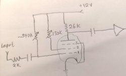
or the like. The secret was to find them in my pentodes. Then, I prepared a jig
in which the cathode of my tube was grounded directly, the control grid biased
thanks to contact potential using a single 10MΩ resistor to cathode, grounding
the suppressor too, the screen tied to +275V with a fixed 10KΩ resistor plus a
100KΩ pote wired as variable resistor (Rheostat). The beam unit was momentarily
unused. The plate was loaded with a 1W resistor to the same power source, and
hooked the oscilloscope probes, one to the plate and the other to the screen
electrode. Surprisingly, the irregularity was there: near 80V of screen bias,
and slowly rotating the pote, a steep of about 15V appeared and it refects in
the anode voltage too. I checked four 12AL11 tubes in the same way, with another
four different values of plate load resistor. I initially I mistrusted from the
pote, and double checked it for deeps in the carbon trace with and ohmmeter and
with a resistor from screen to ground (Simulating screen current), removing the
12AL11 from its socket and the jump didn't appear. So, effectively, it was the
pentode itself who was creating the jump in the screen grid voltage to current
function. So, Reich was true in his affirmation. The only that remain was to
couple the screen to the suppressor removing the earthing piece of wire, and
computing a pair of proper resistor values that, with the jump voltage differences,
can carry the suppressor below the plate current cutoff voltage, (near -4V as the
datasheet sais), or free the anode current, near 0V or perhaps +1V. This table
resumes what I found for the four 12AL11's, numbered arbitrarily:
attachment.php


I also tried 100KΩ anode resistor loads, but at such low values, the
jump vanishes too much to be of interest or importance. The next steep was to
check some of the other type of tubes I have at hand, like the 6BF11 and 6T10.
Rearranging the socket wiring, I found that the 6BF11 has a more pronounced
irregularity and was the final choice, and also performs good with 100KΩ anode
load. Fortunately the value of screen dropping resistor always were about 45
to 50Kê, for the entire tube lot, and a 47KΩ @ 2W was the final chose value.

Then I coupled the screen to the suppressor via a resistor divider and
a small mica cap (220pF) and to the negative rail of -275V. A 6AL5 diode was
used from suppressor to ground to prevent the last to make too positive. A
300Kê small preset was included to adjust the optimum value. I was very happy
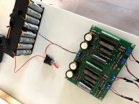
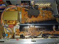
when accidentally the solder iron cable (A Taiyo SL20/200 with an external
TRIAC dimmer) fall near the circuit (The white and blue cotton covered saw in
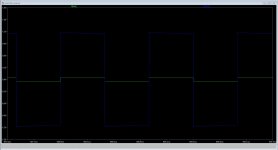
some of the pics) and the pentode acted a true Schmitt trigger (Some pics below).
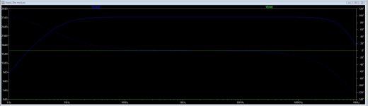
The oscillograms show the anode, screen and supressor waveforms perfectly
triggered and syncronized to the spikes generated by the TRIAC dimmer, their
amplitudes and times, taking into account that the oscilloscope's test leads
has a X10 attenuation not shown in the read out, and that line frequency here
is 50Hz (20mS). The coupling of the cable to the circuit appeared to be more
sensible when placed near the screen-suppressor network that with coupling close
to the grid bias resistor. Burrows used both grid and suppressor coupling trough
germanium diodes.

Once that the Schmitt part of the circuit was OK, the next steep was
to couple a time constant to the input in a manner like a CD40106/74HC14,
hooking a 240VAC 9Kê relay to the beam power unit, a resistive divider from
the pentode anode to the beam unit's control grid. Initially I though to make
the pentode to act in a similar manner than in a device called by F. C. Williams
"Multiar" (1), which uses a transformer to take the regenerative fast action
and a diode as a switch. Also, a small 470pF mica capacitor was paralleled to
provide fast transient coupling from plate to grid. The way in which the time
constant and the values of the elements changed with time and circuit, but
finally I added another 6BV8 tube composed by two independent diodes and a
triode with æ ÷ 33. However, a small problem soonly arise. The triode was used
as cathode follower to provide high input resistance to the time constant network
and low impedance to the switching diode, and the diodes were wired to clamp
the grid voltage between -50V and ground provided by a resistive atenuattor from
the negative bus. But as the plate was to +275V then, the tube cuts off near
-20 or -25V and the full excursion of the voltage swing at the grid wasn't
transferred to the cathode. So, once again, I changed the socket and migrate to
another compactron tube 8B10. As I have only 6.3V heaters, I used it with 6.3V
temporarily with no apparent bright differences or notable performance loose.
(Furtherly I got some 6B10's and replaced them). This compactron has two triodes
like a 12AU7 and two common cathode diodes like a 6AL5 (or the 6CN7). Then, one
of this diodes was used to clamp the grid of the cathode follower to ground,
the other to the same task in the 6BF11's suppressor. The slicer (6) so formed,
has the objective of to take advantage only the fastest part of the exponential
voltage/time rundown waveform where it evolutes quickier and a more defined
behavior is expected, and limit the grid (And the cathode) swing to safe values
as the heater is grounded and the final voltage of the capacitor in absence of
the slicer is near the negative rail. Having freed a diode from the 6AL5, it
was become available to use it as the switch. The second triode was used as a
voltage source, hooking a neon lamp at its grid, biased with 220Kê to the +275V,
and feeding the anode of the follower with this lower voltage value. So, by
this moment the screen of the beam power section was biased with 100KΩ to the
positive rail and soonly I took the idea of to replace again the 6AL5 with the
6BV8 and make a rudimentary voltage regulator moving the neon to the negative
side, providing fixed clamping levels for the grid, and at the same time with
the triode inside the 6BV8 and one of the 6B10 as a "See Saw" voltage stabilizer,
and also feed from this to the screen of the beam power section. The voltage
at the screen is about 60V and suffices to cutout the anode current with -12V
accordingly to the tube data sheet, although the excursion available at the
control grid is of near 90V. But the 60V was OK for the current I need to drive
the relay coil. The current drawn by the relay coil is (275V - 60V) / 9KΩ, or
24mA, well under the tetrode capacities. Then I finally arrived to the actual
configuration (The bottomed voltage of the beam power unit is near 60V).

How it works:
-------------

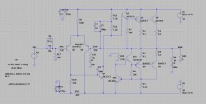
R80 and C80 are the time constants, tied from negative bus and ground.
R89 limits the current drawn by the diode slicer and cuts out any voltage
above ground and below the neon's voltage, near 60-65VDC, negative to ground.
This network also is found in many CMOS devices to prevent ESD and dangerous
levels at their inputs. V82 is a follower, and the diode at its cathode is the
main switch. When powering it on, the pentode 6BF11 starts conducting full anode
current, with the suppressor biased at ground level imposed by the resistive
network and the diode. Anode voltage is low, and the coupling divider to beam
power section maintains the grid well below the cutoff bias, near -90V. As C80
is going more negative (The heaters are lighted some seconds ago), the cathode
follows the grid potential, and diode D2 is cut off because the volage at the
join of P80 and R83 is several volts negative. As well as the grid and cathode
of the follower are going sufficiently negative to direct bias D2, it starts
conducting and pushes the hysteretic network to a still more negative potential.
The Schmitt-like circuit quickly trips (Regeneratively) and the suppressor goes
very negative (-20V) cutting plate current and deriving the electron stream
flow to the screen only, as the control grid here only decides how many current
is able to flow but doesn't participate in the timing mechanism. The fact that
the pentode's cathode current never is fully cutout difficult that its cathode
develop a oxide layer being too many time without cathode current (6). When the
current of the plate of the pentode is cut out, the anode voltage rises violently
and carries the beam power unit in the grid base making it conductive and
energizing the relay at its anode. V81 and V82 (as already said) only make a
rudimentary voltage regulator for the follower and the beam section's screen.
P80 adjust the trip level and the initial conditions of the circuit. C86 makes
with the relay coil a loosy tuned circuit and self damps the spikes at the
moment of removing anode and relay current, and a diode isn't necessary here
because of the natural ruggedness of tubes.

You may feel to find similarities in the circuit with the hysteretic
scheme that can be build using a comparator or an opamp, feeding the non
inverting input with part of the output voltage swing, maintaining the other
input to a reference potential (In my case the control grid), and effectively
is seems similar. However, the mechanism is very different, as here there isn't
any amplification deliberately did to the signal, using a peculiarity of the
pentode's screen characteristic, and there is more similar with the negative
resistance of a neon pilot lamp, or in a SS device, nearest to a DIAC than a
trigger made with opamps.

All this stuff may be made simply wiring a capacitor in series to the
relay coil and feeding it with DC, when the cap charges sufficiently, the relay
liberates its armature and a change in circuit is done. But my idea was also
to explore old knowledge now almost useless.

R96 and the pushbutton discharges the cap during the experimental period,
simplifying the development of the circuit and being a test method.

I didn't check it for repeatability, linearity or constancy of the
timed circuit, as for the purpose for it was designed, those parameters are
unnecessary and irrelevant. Only a small delay of time to switch a relay was
needed.

The circuit uses only two compactron tubes, a noval unit and no SS at
all. Current drawn from the Ebb line is less than 30mA with the relay energized,
a couple of mA's in the negative rail, and a pair of amperes at 6.3VAC.

Conclusions:
------------

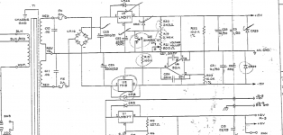
I built a timed relay device that prevents noises and the saturation of
an output autotransformer while the DC coupled audio amplifier is accomodating
its internal parameters, using multiple compactron tubes which was originally
made for FM demodulation and power amplifier in TV sets, and taking advantage
of the pentode's screen grid characteristic to make a hysteretic switching
circuit.

References:
-----------

1) US 2,540,093 from F. C. Williams (06/02/51);
2) Otto Schmitt, "A Termionic Trigger", Proceedings of the IRE;
3) US 2,872,572 from J. L. Burrows, (03/02/59);
4) Samuel Seely "Electron Tube Circuits", McGraw-Hill Book Company, 1950;
5) H. J. Reich, "Trigger Circuits", Electronics (08/39);
6) J. Millman and H. Taub "Pulse and Digital Circuits", McGraw-Hill Book
Company, 1956.

Newbie question about tweeters and factory amp

Just installed a Kenwood head unit, Rockford Fosgate 6x8 three way speakers in the 4 doors, Rockford tweeters in the A columns, and a Rockford 400 amp 4 channel amp. Haven't replaced the factory sub or its amp yet but I still might. This is a 2006 Mercury Mountaineer I'm working on... I used an install kit with a wiring harnesses to convert the main plug from the factory harness to the radio plug and a harness that converted the factory subwoofer plug to RCA plugs out of the head unit. Powered the 4 door speakers off the new 4 channel amp and wired the tweeters into the main harness to use the power from the head unit to power them. (Not sure if that's right or wrong or maybe there's a better way?). Anyway, I'm not impressed with the quality of the sound from the tweeters and I'm getting what seems like a lot more than just bass out of the sub now. Any suggestions on how to improve the tweeter sound quality and / or thoughts on why I'm getting other frequencies out of the sub? Thanks for any advice.

Pioneer SA-1040 Amplifier Fuse Keeps Blowing :

Hi,

I bought this amplifier from Dubai where they have 220 Volts (with 50Hz cycles) but i'm now moved back to Canada where it's 110V (with 60Hz cycles) electricity. The unit does have the voltage selector to select the voltage like 220V-240V and 110V-120V and i'm using 110V-120V.

I have chosen both 110v and 120v but the fuse keeps blowing for some reason. i'm using 3.15 amps glass fuses as always and as recommended. I have attached the service manual and the diagrams as well. some help please.

Attachments

  • SA-1040 Connection.pdf
    SA-1040 Connection.pdf
    677.7 KB · Views: 74
  • 1YADaSy.jpg
    1YADaSy.jpg
    789.4 KB · Views: 185
  • 1930062-caaaa14a-1983-pioneer-silver-face-sa1040-stereo-int-amp-amp-tx940-am-fm-tuner-100-wattsc.jpg
    1930062-caaaa14a-1983-pioneer-silver-face-sa1040-stereo-int-amp-amp-tx940-am-fm-tuner-100-wattsc.jpg
    134.2 KB · Views: 126

Spring cleaning

I've been doing some spring cleaning, and found these toroids.
They are from 500w till 2.2kw and all have dual secondary between 50v to 70 volt, some also have 12v auxiliary.
PM me for more details.

Attachments

  • 20200409_142608.jpg
    20200409_142608.jpg
    797.7 KB · Views: 285
  • 20200409_142540.jpg
    20200409_142540.jpg
    825 KB · Views: 264
  • 20200409_142524.jpg
    20200409_142524.jpg
    564.3 KB · Views: 245
  • 20200409_142456.jpg
    20200409_142456.jpg
    628 KB · Views: 237
  • 20200409_142438.jpg
    20200409_142438.jpg
    846.8 KB · Views: 254

FREE: Heatsinks and trafo (local Northern NJ)

Offer for a local pickup from Wyckoff, NJ.

I have two heatsinks pulled from amplifiers and one trafo from an Onkyo HT receiver. Free to whoever can pick them up from Wyckoff, NJ.

To follow the recommended social distancing, I can leave the stuff in a box outside and you can just pick up.

Attachments

  • heatsink1.jpg
    heatsink1.jpg
    713.1 KB · Views: 137
  • heatsink2.jpg
    heatsink2.jpg
    801 KB · Views: 152
  • trafo1.jpg
    trafo1.jpg
    494.7 KB · Views: 135
  • trafo2.jpg
    trafo2.jpg
    550 KB · Views: 130

Transformer Wish List - FW amp

I had an interesting conversation with Chris the sales manager for Torriod Corporation. A large portion of their business comes from custom transformers. Chris said they are open to supplying small quantities but it only becomes profitable for them (and more affordable for us) if the quantities are in the 5 - 10 range. Their company has an engineer on staff who is knowledgeable in audio...his name is Ming and he sent me an email offering his services. I don't know what specs make for a good transformer for audio...that's where I need your help. I'm thinking of doing a small group buy and see how it goes. They could ship directly from their facility. I have many questions, one of course is at what cost.

Mcintosh C28 Volume Issue

I have a Mcintosh C28 that works very well apart for an annoying issue. One the preamp warms up, the volume will increase by its self, and the volume control can't lower the volume. The volume control does work and can additionally increase the volume, but if the volume control is turned down to zero, it does not cut off the sound. Even if the preamp is turned off and on, the problem still exists.


Once the problem occurs, I unplug the inputs, and plug them back in and allow the center un-grounded phono plug to cause a hum at the stuck volume level, and I do this a few times, and the volume control is restored.


This preamp is stock and has not been recapped, and I'm wondering if this can be a capacitor issue, based on what temporally fixes the problem.


Any ideas?

Help me diy a headphone cable replacement?

An externally hosted image should be here but it was not working when we last tested it.


My cousin works at a major department store. Walmart. He works in the electronics section, and from time to time, people attempt to steal things by cutting the cables and so on. Anyway last week a customer tried to steal a pair of Sony ch700n Bluetooth – noise cancelling headphones, and the customer got caught. My cousins manager gave him the cans, but the only problem is that there is no jack, and wrt the cable itself., Well I'm used to seeing only right/left/common. These have two "regular" (PVC jacketed, pink and white) wires and 3 enamel coated wires(these are thinner than the PVC wires) colored green, gold, and red Presumably the enamel wires are for the mic and noise cancelling circuit? But tbh I am totally fine with skipping the mic, noise cancelling stuff and just using them as regular cans. My question(s)

1.) Which wires do I need *just for using them as headphones*

2) which of those wires is right and which is left?

3) is there a ground?

4) most reliable way to Remove enamel ?


Thank yall

L25D Toroid

Hello there building up 2 x l25d amps. Not gonna worry too much about details other than to say that im having problems with my toroid.

No i had no choice but to use a 500va autotransformer that i aquired.

I have had this on the bench and well it fires up ok and runs and i have +-50v on the two outputs.

Now for some reason when i put it in the case (not touching any of the other parts) and hook it up to my two bridge rectifiers it keeps blowing my breaker.
sometimes i actually stays powered up for say 2 seconds then blows my 10 amp fuse. I have fitted 2 220nf caps across the two outputs but im sure this is not an issue as this is designed for noise supression i think according to the amp schematic i looked at.

Anyhows im just looking to find out if there is something obvious that i am missing. I am very sure that it doesnt need a soft start as it runs ok on the bench. Although i may need it when i get the caps on.
I will try to update with pics tommorow but just cant seem to keep the power from tripping when its in its box. I have tried many ways to power it up and well on its own is the only way ive managed so far.

Any help well appreciated.

Another NOOB question. Dampening material inside a sub?

Sorry for clogging up your subwoofer section with noob questions🙂

I have a whole load of roof flashing tape.. You know, that bitumen based plastic backed type stuff. I used to used it in place of real car audio damping materials back in my poor young man days. Heat it up with a hair dryer, roll/squish/press it on, and it does a fair job of damping vibrations.

So - the question is this: Is it worth chucking some in my 2x 15 sealed down firing subs I'm making? I believe the box will be ery stiff anyways.... But.. it all adds up right?

Is it worth it?

Thanks,
J James.

Power conditioner

I have a pass labs x250 and the transformer has a hum to it. Talked to Pass and they have advised me it could be DC offset on my AC. Have not found the source of it yet. Looking to buy a good power conditioner that will filter DC offset and provide me the cleanest power I can get. Looking for a recommendation of a solid unit for this. Would love to have one of those units that convert to DC and back to clean AC, but dang, a good one is expensive.

Marantz DV7010 need help with drawer immediately closing after opening

Hello,
I'm looking for assistance with a Marantz DV7010 which I want to use to play CD's out in the garage etc.
Notable observations:
1. plugged in, power off: standby LED is NOT on, it should be.
2. service test: Standby LED does light.
3. power on: no faults listed on display; display checks OK in service test.
4. push open button: drawer extends then immediately retracts

The standby LED is controlled by the main microprocessor so the fact that it is off means something, exactly what I can't find out.

According to searches #4 is symptomatic of a dead/dying laser reader.
Apparently the DVD mechanism is a Pioneer unit and replacement parts are readily available.

I just want to check with all y'all and see if replacing the laser is the best first repair.

Thanks for reading this and I definitely appreciate all comments.

FS: IXCP fixed current high voltage current regulators

IXYS IXCP "non switchable" constant current source in TO-220 housing

IXCP10M45 -> 10mA /450V
IXCP50M45-> 50mA/ 450V

39x IXCP10M45 2€ each /70€ for all
43x IXCP50M45 2€ each /75€ for all
all of them for 130€

+ shipping costs from Germany

Datasheet attached

Attachments

  • ixcp.jpg
    ixcp.jpg
    33.4 KB · Views: 185
  • IXCPxM45.pdf
    IXCPxM45.pdf
    552.3 KB · Views: 92

Faulty RF T8002 Amp

Hi!
I Have a RF T8002 Amp that is not working.
I havent been using it for 7-8 years and when I put it away it was because it was broken. Now im gonna try to fix it.

I plugged it in yesterday to see how it acted.
When plugging in B+, GND and Remote signal (without plugging in speakers or RCA)

After about 5 seconds it burned a 40 amp fuse mounted on the the B+ cable.
The amp also makes a howling sound.
After putting in a 60amp fuse the fuse doesnt burn but the cable got very hot.

The howling sound from the amp still goes on.

20200504100047-85.24.204.183.jpg


Those black things mounted on the wall also gets very hot (only the 4 showed in the picture, the others dont get hot)

Could those be faulty and where can I buy them?
Or can it the something else that is broken?

Appreciate every help I can get.

C-notes as outdoor speakers?

Hey

I have a small patio (~6*4m) that I would like to build some speakers for. I'm not looking for crazy volume, just something that sounds pretty good.
Do you think a pair of C-notes would work, as pictured? I was thinking I could build them out of plywood and put some mesh in the ports. They would be quite protected under the eaves and I would also be taking them down before winter.
BAutqEt.png


Can you think of any other design/kit that would work better for a similar amount of money?

help with vintage Lexicon power supply

My Lexicon 200 digital reverberator won´t power up.
I have isolated the problem to a missing positive rail on the dual+-15v supply. The negative side is fine. All other voltages (5v, 12v...)are also fine.
What I see is U5 has voltaje at the input but nothing at the output.
The service manual says the dual 15v power supplies are interlocking so when one goes down the other should as well. If not, one should check U6 and Q5.
This seems to be the case here.

I have no degree in electronics whatsoever but am handy and have a solder station and tester, no oscilloscope.
Can anybody help with what I might do next?
Tthanks in advance

Attachments

  • power supply.png
    power supply.png
    162.5 KB · Views: 177
  • troubleshooting.png
    troubleshooting.png
    176.7 KB · Views: 187
Projects by fanatics, for fanatics
Get answers and advice for everyone wanting to learn the art of audio.
Join the Community
507,706
Members
7,885,117
Messages

Filter

Forum Statistics

Threads
406,077
Messages
7,885,117
Members
507,706
Latest member
thatchacha10